
Related Manuals for Suntex SC-2300

Summary of Contents for Suntex SC-2300
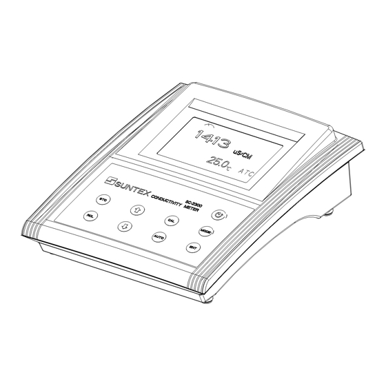
- Page 1 Microprocessor Operation Manual Benchtop Conductivity/ Resistivity Meter SC-2300...
-
Page 2: Table Of Contents
Content Table 1. Specifications 2. Configuration 2.1 Display 2.2 Socket 2.3 Keypad 3. Operation 3.1 Measurement 3.2 Measurement function and file bit shift 3.3 Temperature function and compensation 3.4 Auto Read 4. Settings Block diagram of settings 4.1 Parameter settings 4.1.1 Entry of set-up mode 4.1.2 Settings of measurement mode 4.1.3 Settings of data deletion... - Page 3 5.3.1 Electrode coefficient calibration 5.3.2 Standard solution single-point calibration 5.3.3 Standard solution five-point calibration 5.3.4 Error message 6. Instruction set for RS232 7. Alternative fittings 8. Failure recovery 9. Maintenance...
-
Page 4: Specifications
1. Specifications Model SC-2300 µS/ mS/ MΩ/ Salt/ TDS/ TEMP Function 0.00 uS/cm ~ 200.0 mS/cm in 5 measuring ranges for manual or auto switch Cond. 0.00~100.00 MΩ- cm Res. 0.0~70.0ppt Range Salt 0~2000ppm -10.0~+110.0°C TEMP 0.01µS/cm Cond. 0.01 MΩ-cm Res. -
Page 5: Configuration 2.1 Display
2. Configuration 2.1: Display: Set-up Measurement mode mode Measurement Read mode unit Auto temperature Auto mode compensation Calibration Time reminder mode Data Data transferring storage speed mode mode Storage ID battery reminder Data reading Data Storage ID /Transferring mode 2.2 Socket: POWER : DC 6V Adaptor socket RS-232 : RS-232 output socket... -
Page 6: Keypad
2.3 Keypad: : Power switch--- Push it to power on and push it again to power off : Cond./Res./Salt/TDS measurement shift key; pushing it at any time to back to measurement mode : Enter calibration mode : Auto read--- Push one time for startup and push again for cancellation. : Upward or leftward key : Downward or rightward key : (ENTER) confirmation, execution, and confirmation for RS-232 manual output... -
Page 7: Operation
3. Operation 3.1 Measurement: Push key to power on the instrument. It will automatically show last measurement and be ready for new measurement. 3.2 Measurement function shifting: 1. Push 【MODE】 to shift among Cond., Salt, and TDS in Cond. Mode. This function is unavailable in Res. -
Page 8: Temperature Function And Compensation
3.3 Temperature measurement and compensation: Auto Temp. Compensation: Auto recognition of temperature probe system. (NTC30K or PT1000) Push to adjust the temperature within in ±5℃. Push keys simultaneously to back to the original value. Manual Temp. Compensation: Enter MTC 25℃ automatically if no temperature probe. Push to adjust the temperature. -
Page 9: Settings Block Diagram Of Settings
4. Settings Block diagram of settings Push 【MODE】+ Power off 【MODE】 Release 【STO】+ 【CAL】+ Push ,, , Push to enter measurement mode 【STO】 Release 【CAL】 Release to delete all stored data Settings of for system reset System time settings Baud rate settings Data overwriting settings measurement mode (RS 232) -
Page 10: Parameter Settings
4.1 Parameter settings: 4.1.1 Entry of set-up mode: In the power-off status, push 【MODE】 first and then push 【 】 to power on the machine; then please release 【 】 first and then 【MODE】to enter the parameter setting mode. to select. 4.1.2 Settings of measurement mode: Push 【ENT】to enter Push... -
Page 11: Settings Of Baud Rate (Baud)
4.1.4 Settings of baud rate (BAUD): Enter “Settings of RS-232 baud rate” Push【ENT】to enter Push Push to select to select Push to select Push【ENT】to confirm it Enter “Settings of system... -
Page 12: Settings Of System Time
4.1.5 Settings of system time: Enter “Settings of system time” Push【ENT】to enter Push to modify the year, then push【ENT】to confirm it Push to modify the month, then push【ENT】to confirm it Push to modify the date, then push【ENT】to ensure Push to modify the hour, then push【ENT】to confirm it Push to modify the... -
Page 13: Deletion Of All Stored Data
4.2 Deletion of all stored data: In the power-on status, push【STO】first and then【 】; after that, release【 】first and then release【STO】to enter the data deletion mode. (Data Clean) Pus h 【ENT】 to co nfirm to delete all stored data or push 【MODE】... -
Page 14: Block Diagram Of Calibration And Temperature Compensation Settings
Block diagram of calibration and temperature compensation settings Settings in specific resistivity Settings in conductivity mode Calibration and temperature Power on compensation settings. Power on Push 【ENT】+【CAL】 Push【ENT】+【CAL】 Measurement Electrode coefficient Standard solution Measurement temperature settings temperature coefficient calibration settings calibration settings settings Push↑↓... -
Page 15: Settings Of Calibration Parameter
4.4 Settings of calibration parameter: In the power-on status, push 【ENT】 first and then push 【CAL】 to enter set-up mode of calibration parameter. Use to select. 4.4.1 Electrode coefficient and calibration parameter: Electrode coefficient and calibration parameter 【ENT】to enter the settings Push of calibration temperature compensation coefficient... -
Page 16: Standard Solution Calibration Parameter
4.4.2 Standard solution calibration parameter: (Only suitable when the measurement unit is conductivity) Push【ENT】to confirm it Push to select Push【ENT】to confirm it Back to measurement mode 4.4.3 Temperature compensation coefficient: Push【ENT】to confirm it Push Push to select to select Push【ENT】to confirm it Push to set the coefficient value Push【ENT】to confirm it... -
Page 17: Block Diagram Of Operations In Measurement Mode
Block diagram of operations in measurement mode Power on Storage Transmission mode Manual read and transmission Push 【RCL】 to shift circularly among 4 modes Data store full Auto transmission Auto store Manual store Push【ENT】+【RCL】 The calibrated data is The stored data is transmitted The stored data is Push 【ENT】+【STO】... -
Page 18: Auto/Manual Data Storage
4.5 Auto/manual data storage: 4.5.1 Auto storage: 4.5.2 Manual storage: In the measurement mode, push【ENT】 In the measurement mode, push【STO】 first and then push【STO】to enter the to enter manual store page. auto continual storage set-up mode. 【ENT】 Push to confirm it Appear the original ID. -
Page 19: Data Readout And Output
4.6 Data readout and output: 4.6.2 Manual readout and transmission: In the measurement mode, push【RCL】to 4.6.1 Auto transmission: In the measurement mode, push【ENT】 shift among 4 modes circularly, and push【ENT】 first and then push【RCL】to enter auto to enter. transmission. Push【ENT】to enter, and the recently stored data will appear Push to set the minute, and push【ENT】for confirmation and... - Page 20 B. Transmit the stored data through RS-232 C. Read the calibrated data on the display Transmit all stored data through RS-232 C.1 Read the calibrated data on the display 【ENT】 Push to transmit Push【ENT】, and it will show the standard After the transmission, solution value and electrode coefficient back to measurement...
- Page 21 C.2 Read simple-point calibration data of standard solution (when the calibration parameter is set as Std 1P calibration). Push【ENT】to enter, and the data and electrode coefficient of standard solution appear Push【ENT】and the calibration record year appears Push【ENT】, and the calibration record date appears Push【ENT】and the calibration record time appears 【ENT】...
- Page 22 C.3 Read five-point calibration data of standard solution (when the calibration parameter is Push【ENT】and the calibration record set as Std 5P calibration). date appears Push【ENT】and the calibration record time Push【ENT】, show the calibration value of Buffer 1. If there is no data, it will show “NULL.” Push【ENT】...
-
Page 23: Calibration Block Diagram Of Calibration
5. Calibration Block diagram of Calibration Power on Conductivity mode Specific resistivity mode Push【CAL】 Use ↑↓keys to select known standard solution value Use ↑↓keys to select Push 【MODE】 Use ↑↓keys to standard solution Use ↑↓keys to value, including: select suitable 10.00uS/cm, select known coefficient... -
Page 24: Standard Solution Preparation
5.1 Standard solution preparation: Put reagent KCl in an oven of 150℃~180℃ for 5 hours, and then put it in a dry container until it cools down to the ambient temperature. Dissolve 0.7456 g KCl powder into 1 kilolitre pure water to be 0.01N KCl standard solution (1413µS/cm). -
Page 25: Standard Solution Five-Point Calibration
5.3.3 Standard solution five-point calibration: 1. When the calibration parameter is set as five-point calibration (see 4.4), push【CAL】to enter Standard solution five-point calibration, and then push【ENT】to enter the first CAL1 page. Push【MODE】 at any time will allow you intermit the calibration and back to the measurement mode. -
Page 26: Instruction Set For Rs232
6. Instruction set for RS232 The communication between the instrument and the Windows Hyper Terminal is set as follows: 1. Click 【Start】on the lower left, and select 【All Programs】→【Accessories】→ 【Communication】 →【Hyper Terminal】, and the display will show a window of “Hyper Terminal”. 2. -
Page 27: Failure Recovery
8. Failure recovery Failure phenomenon Possible causes Disposition ERR1 The electrode coefficient has a too large Replace new standard solution for another deviation when using the standard calibration. For others, please refer to the solution to calibrate. disposition of measurement deviation in the following.
Need help?
Do you have a question about the SC-2300 and is the answer not in the manual?
Questions and answers