Table of Contents
Advertisement
Quick Links
Download this manual
See also:
Instruction Manual
1
INSIDE THE BOX ...
This instruction manual describes the installation and commissioning
of the M20 load monitor. The M20 supervises induction motor driven
equipment and provides alarms when abnormal conditions are
detected. The M20's ability to provide reliable monitoring & protec-
tion ensures production equipment is optimised and expensive break-
downs and interruptions are minimized. Due to the special method of
subtracting motor power losses, the monitor is able to accurately mea-
sure the shaft power supplied by the motor to the application. This
advanced technique allows the M20 to monitor the "application" load
only as opposed to the "total" motor load, which includes the varying
motor losses.
• Check the delivery. Your shipment should contain the M20 load
monitor, a current transformer and this instruction manual.
• Check carefully that the ordered equipment complies with the
motors input voltage and that the current transformer rating is as
stated on the delivery packaging.
• Check that the contents have not been damaged in shipping.
Note!
If in doubt contact your supplier before starting to install or commissioning
the product.
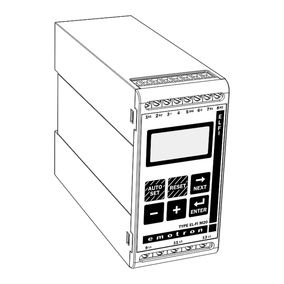
®
EL-FI
M20
SHAFT POWER MONITOR
INSTRUCTION MANUAL
Motor shaft output power measurement
Continue
3
ALTERNATIVE EXAMPLE FOR SINGLE-PHASE
CONNECTION
This wiring example shows the deviant power connection to be made
with regard to a single-phase connection. Refer to fig. 1 for the
remaining wiring.
L1
N
Fig 2. Single-phase connection example.
EXAMPLE - DIGITAL INPUT
The Digital Input use the terminals 5 (DIG) and 6 (C-reference). It can
have either a VAC or a VDC signal. See also section 7 ADVANCED
FEATURES.
MONITOR
Fig 3. Wiring example for digital input.
6
C
L1
7
R1
L2
8
R2
L3
MONITOR
5
DIG
S1 S2
1
2
CTMxxx
K1
M
-
6
C
( )
~
+
( )
~
DIG
5
2
SAFETY
• Study this manual thoroughly before installing and using the
monitor.
• The monitor must be installed by qualified personal.
• Always disconnect supply circuits prior to installing.
• The installation must comply with standard and local regulations.
• Pay special attention to this SAFETY section and the part marked
"CAUTION!" in the OPERATION section.
• Should questions or uncertainties arise, please contact your local
sales outlet or see section 11 SERVICE.
Note!
Do not remove or break the seal on the housing. The warranty will be can-
celled.
SELECTION CURRENT TRANSFORMER
4
FOR MOTORS LESS THAN 100A
1. Check the rated motor current on the motor plate.
2. Compare this value with the current in table 1.
3. From table 1, select the current transformer and the appropriate
numbers of windings.
Note!
Max length of the CTM cable is 1 m (39.37 in).
EXAMPLE:
• Rated motor current = 12A.
• Select 10.1-12.5A from the first colon in table 1.
• This gives:
- CTM025 with 2 windings.
CURRENT TRANSFORMER TYPE
RATED MOTOR
NUMBER OF WINDINGS
CURRENT [A]
CTM 010
CTM 025
CTM 050
CTM 100
0.4 — 1.0
10
1.01 — 2.0
5
2.01 — 3.0
3
3.1 — 5.0
2
5.1 — 10.0
1
10.1 — 12.5
2
12.6 —25.0
1
26.0 — 50.0
1
51.0 — 100.0
1
Table 1. CT less than 100A.
WIRING
3
This wiring example shows how the M20 can be used to control the
starting and stopping circuit of the motor. Other wiring configura-
tions are possible.
1. The current transformer CTMxxx must be placed in the same
phase that is connected to terminal 9, phase L1.
2. For single-phase connection see fig 2.
L1
L2
L3
N
Max.240V
Inpower
NOTE!
3 4
down,bothrelays
arealwaysN.O.
A+
A-
6
C
L1
7
R1
L2
8
PRE-
R2
L3
ALARM
MONITOR
-Reset
5
DIG
-Autoset
S1 S2
-Block
1
2
CTMxxx
K1
N
K1
M
3
Fig 1. Connection example
Note!
If the START/STOP is connected according to fig. 1, it is recommended that
terminals 6 and 7 be by-passed during programming. After the programming
is completed the by-pass must be taken out.
Note!
Normally the appropriate Current Transformer (CT) will have been ordered
and shipped with the M20, check that this is the case; contact the supplier
if in doubt.
L1
L2
L3
CTM025
2windings
P2
1
2
S1 S2
MONITOR
M
3
Fig 4. Example CTM 025 with 2 windings for an 12 A motor.
Note!
The transformer connection and orientation are not polarity sensitive.
Fig 5. Example 1 and 3 windings.
AC
STOP
START
Advertisement
Table of Contents

Subscribe to Our Youtube Channel
Related Manuals for Emotron EL-FI M20

Summary of Contents for Emotron EL-FI M20
- Page 1 WIRING INSIDE THE BOX … SAFETY This wiring example shows how the M20 can be used to control the This instruction manual describes the installation and commissioning • Study this manual thoroughly before installing and using the of the M20 load monitor. The M20 supervises induction motor driven starting and stopping circuit of the motor.
- Page 2 WINDOW MENU Continue OPERATION Start Window Actual Load FOR MOTORS GREATER THAN 100A Alarm window Overview 1. Check the rated motor current on the motor plate. Actual Line Voltage Control terminals: LCD display: 2. Compare this value with the current in table 2. CTM010 Function (window) number 2windings...
- Page 3 Programming Monitor Function (Window 05) Set the START DELAY (window 31) Set Alarm levels with AUTOSET 1. Go to window 05. The default selection is OVER- and UNDER- A START DELAY must be set to allow the motor and machine to The AUTOSET command performs a measurement of the actual LOAD monitor.
- Page 4 0-745 MAX Main Alarm 0-100 power in kW EU (European Union) specifications margin Emotron AB reserves the right to alter product specifications without Measured shaft 0-125 EN 50081-1, EN 50081-2, MAX Pre-Alarm 0-100 prior notification. No part of this document may be reproduced with-...
Need help?
Do you have a question about the EL-FI M20 and is the answer not in the manual?
Questions and answers