Table of Contents
Advertisement
Advertisement
Table of Contents

Related Manuals for Emotron M20

Summary of Contents for Emotron M20
- Page 1 Emotron M20 Shaft power monitor Instruction manual English...
-
Page 3: Table Of Contents
Contents Inside the Box................3 Safety ..................4 Description.................. 5 Getting Started ................7 Please note ....................7 Connection and set-up before first start ........... 7 First start ..................... 8 Manual setting of alarm levels, alternative A ........... 9 Manual setting of alarm levels, alternative B........10 Manual setting of alarm levels, alternative C ........ - Page 4 Setting alarm levels with Auto set............28 Setting the Response Delay (windows 32 and 34)........ 29 Advanced Features ..............31 Setting alarm levels manually (windows 11-14) ........31 Troubleshooting ............... 41 Technical Data ................. 43 Parameter List................48 Service ..................51 CG Drives &...
-
Page 5: Inside The Box
Please check the delivery. Despite the fact that all products from CG Drives & Automation are carefully inspected and packed, transport damage may occur: • Your shipment should contain the Emotron M20 shaft power monitor, a current transformer, 2x terminal covers (option*) and this instruction manual. -
Page 6: Safety
Safety • Study this manual thoroughly before installing and using the monitor. • The monitor must be installed by qualified personnel. • Always disconnect supply circuits prior to installing. • The installation must comply with standard and local regulations. • Pay special attention to the information in this chapter and the parts marked CAUTION in the Operation and Programming chapters. -
Page 7: Description
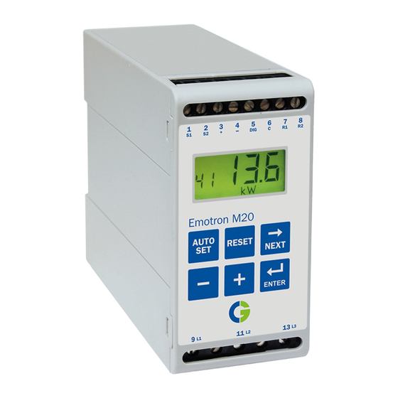
The Emotron M20 uses the motor as its own sensor and no external sensors or extra cabling are required. Due to the special method of subtracting motor power losses, the monitor is able to accurately measure the shaft power supplied by the motor to the application. - Page 8 The Emotron M20 shaft power monitor offers advanced multi-function monitoring and a display for load indication and parameter setting. It is ideal protecting many different applications including pumps in general, centrifugal pumps, magnetic pumps, screw and impeller pumps, mixers, scrapers, crushers, conveyor systems, etc.
-
Page 9: Getting Started
1 and 2 in chapter 6 of this manual. Connection and set-up before first start 1. Connect the Emotron M20 according to chapter 5 and Fig. 1. 2. Make sure all safety measures have been taken and switch on the supply voltage. -
Page 10: First Start
NOTE: If any window parameter is manually adjusted, the display will flash the new value to indicate that a change has been made. The Enter key must be pressed for the M20 to accept this new value. CG Drives & Automation 01-5958-01r0... -
Page 11: Manual Setting Of Alarm Levels, Alternative A
Manual setting of alarm levels, alternative A Running and setting at normal load • Start the motor/machine or pump and let it run at normal load, until the Start Delay (window 31) has expired. • Read off the load on the monitor display, e.g. 65%, window 01 (or kW/HP). -
Page 12: Manual Setting Of Alarm Levels, Alternative B
Manual setting of alarm levels, alternative B Running and setting at maximum load as well as at minimum load • Start the motor/machine or pump and let it run at maximum load, until the Start Delay has expired. E.g. fill the conveyor with maximum allowed goods. •... -
Page 13: Wiring
Wiring The following wiring diagram provides an example of how the M20 can be connected to control the start/stop circuit of a three-phase motor, Fig. 1. Connections to a single-phase motor are described later in this manual (Fig. 2) as are the programming changes necessary for such applications. The default setting for the M20 is 3-phase. - Page 14 NOTE: in power down, both relays are alwas N.O. Max. 240 VAC (alt. 0 VDC-) Stop Please see CTM information on Page 11. Start NOTE: Monitor voltage see Note below. N (alt. 48 VDC+) Fig. 1 Connection example NOTE: If the START/STOP is connected as per Fig. 1, it is recommended that terminals 6 and 7 be bypassed during programming.
-
Page 15: Alternative Example For Single-Phase Connection
Alternative example for single-phase connection This wiring example shows the connections required for single-phase applications. Refer to Fig. 1 for the remaining wiring. S1 S2 CTMxxx NOTE: Monitor voltage, see note below. Fig. 2 Single-phase connection example. NOTE: In Fig. 2 make sure that the monitor voltage range e.g. 1x100-240 VAC matches the connected motor/“line –... -
Page 16: Example - Digital Input
Example - digital input The digital input uses terminals 5 (DIG) and 6 (C - reference). Either a VAC or a VDC signal may be used. Connect + to terminal 5 (DIG) and - to terminal 6 for VDC signal. Please note the polarity when DC voltage is used. See also Fig1 and terminal 6: Max. - Page 17 12.6 –25 26 – 50 51 – 100 In order to ensure an accurate calibration of the M20, it is essential that you use the correct CTM and apply the exact number of windings in accordance with the above table.
- Page 18 Example CTM 025 with 2 windings for a 12 A motor NOTE: The current transformer connection and orientation are not polarity sensitive, but must be connected to the same phase that is being referenced for terminal 9 of the M20. Fig. 5 Example 1, 2 and 3 windings.
-
Page 19: Motors Greater Than 100 A
151 – 250 500:5 CTM 010 251 – 500 1000:5 CTM 010 501 – 999 NOTE: Check that the appropriate Current Transformers has been ordered and shipped with the M20. Contact the supplier if in doubt. CG Drives & Automation 01-5958-01r0... - Page 20 500:5 with 1 winding for a 260 A motor. NOTE: The transformer connection and orientation are not polarity sensi- tive, but must be connected to the same phase that is being referenced for terminal 9 of the M20. CG Drives & Automation 01-5958-01r0...
-
Page 21: Operation
Operation Make sure the enclosed plastic (rubber) insert (if ordered, optional) covers the monitor terminals before you start programming. Overview Function (window) number 1 S1 Current transformer input Function Value 2 S2 Current transformer input Analogue output Warning signal Analogue output Start, response delay or 5 DIG External RESET or AUTO SET block timer active... -
Page 22: Window Menu
Window menu Start window Measured shaft power Alarm indication Measured line voltage Measured current Parameter Lock Monitor Function Factory defaults MAX Main Alarm MAX Pre-Alarm Analogue Output MIN Pre-Alarm Block Timer MIN Main Alarm Digital Input MAX Main Alarm margin MAX Pre-Alarm margin Relay function Pre-Alarm Relay 2... -
Page 23: How To Change A Value
• The Alarm window only appears if an Alarm output is active. • The Actual Load window appears after power up. • Use the key to scroll through the menu. Scroll back by pressing and holding at the same time as the key is pressed. -
Page 24: Programming
Programming Set measurement unit, kW or HP 8.1.1 Selecting the unit of measurement The unit of measurement can be set to kilowatts or horsepower both as absolute or relative values. This setting is valid for the alarm levels, rated motor power and the actual load read-out in window 01. - Page 25 Programming 1. Go to window 01. 2. Press and hold simultaneously for 3 seconds. RESET RESET 3. The next unit of measurement is set and appears for 2 sec (see examples). Repeat to select the desired measurement unit according to the table. For 2 seconds Read-out example 3.
-
Page 26: Setting Rated Motor Power And Current (Window 41 And 42)
Setting rated motor power and current (window 41 and 42) The rated motor power and the rated motor current must be set in windows 41 and 42. Example motor plate: TYPE: T56BN/4 948287 Prot. IP: Serv: Cos : 0.78 Is. Cl: V:Y/ A:Y/ 240/415... -
Page 27: Setting Number Of Phases (Window 43)
Setting number of phases (window 43) The number of phases must be set according to the number of motor phases. Default is 3 phases, see also chapter 5, Wiring. 8.3.1 Programming 1. Go to window 43 (default = 3PH). 2. Press to set the number of phases to 1 if a single-phase motor is used. - Page 28 Overload and underload Monitor START UNDERLOAD OVERLOAD MAX Main alarm [11] MAX Pre-alarm MAX Main [12] alarm margin MAX Pre-alarm [21] OPERATION AREA margin [22] Auto set level Normal load MIN Pre-alarm MIN Main margin [23] alarm margin MIN Pre-alarm [24] [13] MIN Main alarm...
-
Page 29: Setting The Start Delay (Window 31)
Setting the Start Delay (window 31) To avoid false alarms during start up a Start Delay must be set to allow the motor and machine to speed up and to allow the power in-rush currents. Programming 1. Determine in seconds how long it takes for the motor and machine to reach speed and for the power in-rush to pass. -
Page 30: Setting Alarm Levels With Auto Set
Setting alarm levels with Auto set The Auto set command performs a measurement (momentarily) of the actual motor load and automatically sets the relevant alarm levels depending on the selected monitor function. Protection Margin (Monitor Value Margins Alarm Level at Alarm function (Default... -
Page 31: Setting The Response Delay (Windows 32 And 34)
3. The display shows “SEt”, to confirm that the Auto set level has been measured and the alarm levels have been set. The display reverts to window 3 seconds AUTO AUTO 4. If the alarm levels are too high or too low, readjust the appropriate MARGINS (see table) and perform a new Auto set. - Page 32 Example: Response Delay 0. 5 0. 5 Alarm level Response Delay [32] Alarm Fig. 9 Response Delay. CG Drives & Automation 01-5958-01r0...
-
Page 33: Advanced Features
Advanced Features Setting alarm levels manually (windows 11-14) The alarm levels can be set manually, without using the Auto set. These levels can also be readjusted, e.g. for fine-turning, after an Auto set has been performed. See also section 4.3 to 4.6. Protection (Monitor function Alarm levels (Window) Default... - Page 34 Setting margins (windows 21-24) The margins for the Auto set can be changed manually. After the adjustment, the Auto set action must be performed again. Protection (Monitor function Window Default window 05) 21: MAX Main Alarm margin 22: MAX Pre-Alarm margin OVER- and UNDERLOAD (Default) 23: MIN Pre-Alarm margin...
- Page 35 Setting main alarm latch (window 61) The main alarm latch keeps the main alarm output active, even if the alarm condition has been removed. A latched alarm output can be reset by: • The reset key • External reset via digital input (see window 81). •...
- Page 36 Setting block timer (Window 82) To set the timer for the blocking time after the Block command is released (see also window 81). Default = 0.0 sec. MAX Main Alarm level [11] MAX Pre-Alarm level [12] Auto set level Relay 1 Main alarm Relay 2 Pre-alarm Pre-Alarm Blocked Block signal high on terminal 5 DIG [81]...
- Page 37 4. 2 0 SHAFT 100% 20.4 20.0 0.20 4.20 Output Fig. 12 CG Drives & Automation 01-5958-01r0...
- Page 38 Setting analogue output load range: P-span (window 92-93) With windows 92 and 93 the full scale of the analogue output can be set according to the minimum and maximum load (P-span). 1. In window 91, press RESET and + for two seconds until “on” shows. Windows 92 and 93 are now active.
- Page 39 NOTE: The symbol appears in all windows. Resetting to factory defaults (window 99) The factory defaults are reset by entering “dEF” in window 99. If window 99 shows “USr” it indicates that the settings have been changed to user specific settings.
- Page 40 “jam” occurs. Reversing the motor may remove the blockage. Should one reverse cycle not be enough to release the material, the M20 will repeat this operation up to a maximum of 5 cycles (window 36, 0-5 start attempts). Relay R1 = forward, relay R2 = reverse.
- Page 41 NOTE: In order to accomplish the above result, it will be necessary for a forward and reversing motor starter to be installed. See Fig. 15 Example of connection with a forward and reversing motor starter (contactor). For more information contact your local sales outlet or visit us at: www.emotron.com Alarm/Stop 20 mA (Blocking) Max 240 VAC (alt.
- Page 42 Alternative auxiliary circuit 0VDC- CTMxxx 24VDC+ Fig. 16 Example of auxiliary circuit when VDC is used. The example above can be used when a high VDC signal output is required. CG Drives & Automation 01-5958-01r0...
-
Page 43: Troubleshooting
Troubleshooting Ensure that the installation has been correctly carried out, e.g. check the terminals and that the cables are properly stripped. The monitor is maintenance-free. However, you should regularly check wirings and terminals etc. Problem Solution Check the connection of the current transformer(s). - Page 44 Problem Solution Check the alarm levels in windows 11 to 14. If incorrect readjust the levels or perform an The monitor always Auto set. gives an alarm Check if the monitor is programmed for “latched alarm” (window 61=on). If so reset the monitor by pressing the reset key.
-
Page 45: Technical Data
Technical Data 45x90x115 mm (1.77" x 3.54" x 4.53") Dimensions (WxHxD) 45mm (1.77’‘) 115mm(4.53) ’‘ Mounting 35 mm DIN rail 46277 Weight 0.30 kg (10.5 oz) Supply voltage 1x100-240 VAC, 3x100-240 VAC, 3x380-500 VAC or 3x525- (±10%) 690 VAC Frequency 50 or 60 Hz Current transformer;... - Page 46 IP20 RoHS directive 2002/95/EC Approved to CE (up to 690VAC), UL and cUL (up to 600 VAC) Article Designation number 01-2520-2 Emotron M20 1x100-240/3x100-240 VAC 01-2520-4 Emotron M20 3x380-500 VAC 01-2520-5 Emotron M20 3x525-690 VAC CG Drives & Automation 01-5958-01r0...
- Page 47 Technical Data for Current Transformer (CT) Dimensions Type Weight* Mounting (WxØ) CTM 010 27 (35) x Ø48 mm 0.20 kg 35mm DIN rail 46277 CTM 025 27 (35) x Ø48 mm 0.20 kg 35mm DIN rail 46277 CTM 050 27 (35) x Ø48 mm 0.20 kg 35mm DIN rail 46277 CTM 100 45 (58) x Ø78 mm 0.50 kg...
- Page 48 Accessories and documentation Article Designation number 01-2471-10 Current Transformer (CT) CTM010, max. 10 A 01-2471-20 Current Transformer (CT) CTM025, max. 25 A 01-2471-30 Current Transformer (CT) CTM050, max. 50 A 01-2471-40 Current Transformer (CT) CTM100, max. 100 A 01-2368-00 Front Panel Kit 1 (2x terminal covers included) 01-4136-01 2x Terminal covers 01-5958-00 Instruction manual (Swedish) 01-5958-01 Instruction manual (English)
- Page 49 US specifications FCC (Federal Communications Commission). This equipment has been tested and found to comply with the limits for a Class A digital device pursuant to Part 15 of the FCC Rules. These limits are designed to provide reasonable protection against harmful interference when the equipment is operated in a commercial environment.
-
Page 50: Parameter List
Parameter List Window Function Range Default Custom Symbol Alarm indication Measured shaft power in % of rated 0-125 power Measured shaft 0-745 power in kW Measured shaft power in % of rated 0-125 power Measured shaft 0-999 power in HP Measured line voltage 90-760 V Measured current 0.00-999 A... - Page 51 Window Function Range Default Custom Symbol 0-125 0-745 MIN Pre-Alarm (relay 0-125 0-999 0-125 0-745 MIN Main Alarm (relay R1) 0-125 0-999 MAX Main Alarm 0-100 margin MAX Pre-Alarm 0-100 margin MIN Pre-Alarm 0-100 margin MIN Main Alarm 0-100 margin Start delay 1-999 Response delay over-...
- Page 52 Range Default Custom Symbol Alarm at no motor on/OFF current Main Alarm relay R1 nc/no Pre-Alarm relay R2 nc/no 0 = M20 Relay function 1 = DLM 2 = Reverse Digital input rES/AU/bLo Block timer 0.0-90 0.20/4.20/ Analogue output 0.20 20.0/20.4...
-
Page 53: Service
Service This manual is valid for the following model: Emotron M20 (from software version R3b) Document number: 01-5958-01 Document version: Date of release: 2012-04-02 CG Drives & Automation Sweden AB reserves the right to alter product specifications without prior notification. No part of this document may be reproduced without permission from CG Drives &... - Page 54 CG Drives & Automation 01-5958-01r0...
- Page 56 CG Drives & Automation Sweden AB Mörsaregatan 12 Box 222 25 SE-250 24 Helsingborg Sweden T +46 42 16 99 00 F +46 42 16 99 49 www.cgglobal.com / www.emotron.com...
Need help?
Do you have a question about the M20 and is the answer not in the manual?
Questions and answers