Table of Contents
Advertisement
Quick Links
Advertisement
Table of Contents

Subscribe to Our Youtube Channel
Related Manuals for Santec ECL-200


Summary of Contents for Santec ECL-200
- Page 1 Artisan Technology Group is your source for quality new and certified-used/pre-owned equipment SERVICE CENTER REPAIRS WE BUY USED EQUIPMENT • FAST SHIPPING AND DELIVERY Experienced engineers and technicians on staff Sell your excess, underutilized, and idle used equipment at our full-service, in-house repair center We also offer credit for buy-backs and trade-ins •...
- Page 2 External Cavity Tunable LD Module ECL-200 OPERATION MANUAL Artisan Technology Group - Quality Instrumentation ... Guaranteed | (888) 88-SOURCE | www.artisantg.com...
- Page 3 ECL-200 OPERATION MANUAL Notes to Users 1) Copyright 1997 Santec Photonics Laboratories. All rights reserved. No part of this Operation Manual may be reproduced or transmitted in any form or by any means, electronic or mechanical, for any purpose, without the prior written permission of Santec.
- Page 4 Thank you very much for your having purchased our product, Wide-band Wavelength Tunable LD Light Source ECL Series. This Operation Manual contains information necessary for the operation of ECL-200, and it is indented for those with sufficient knowledge enough to conduct the evaluation of laser danger and its safe control.
- Page 5 General Description Constitution of this Operation Manual and How to Read it This Operation Manual should be read before operating ECL-200. This Operation Manual consist of 14 chapters, and the contents of each are as follows: Chapters 1 through 8 describe the outline of the product, notes on safety, and installation of the product.
- Page 6 ECL-200 EXTERNAL CAVITY TUNABLE LD MODULE Marking on the instrument This indicates that caution is required. Please refer to the operation manual. This indicates there is a danger due to laser radiation. Do not look directly at the laser beam or look at the beam by eye through any optical instrument.
- Page 7 ECL-200 OPERATION MANUAL Explanation of Terms The meanings of the following terms used in this Operation Manual are defined as below: (1) Meaning DANGER --- This indicates pressing DANGER, and if it is not DANGER!! avoided, personnel death or serious injury results, therefore, it is the most emphasized special information.
-
Page 8: Table Of Contents
ECL-200 EXTERNAL CAVITY TUNABLE LD MODULE Table of Contents Introduction Constitution of this Operation Manual and How to Read it Explanation of Terms 1. Outline of Product 2. Configuration 3. Specifications (Standard Spec.) 4. Principle of Operation 5. Safety Notes and Safety Devices 6. - Page 9 9-4. Operation in each mode 9-5. Coherence Control 9-6. Setting wavelength 9-6-1. Rough adjustment function of transmission wavelength 9-6-2. Fine adjustment of transmission wavelength 9-6-3. How to set transmission wavelength of ECL-200 9-11 9-7. How to shut power OFF 9-12 10. Communication 10-1 10-1.RS-232C...
-
Page 10: Outline Of Product
ECL-200 EXTERNAL CAVITY TUNABLE LD MODULE Outline of Product ECL-200 is a Manual Tunable LD Light Source Unit developed for multi light source on the basis of our technologies accumulated in our external cavity type semiconductor laser light source series. - Page 11 ECL-200 OPERATION MANUAL Artisan Technology Group - Quality Instrumentation ... Guaranteed | (888) 88-SOURCE | www.artisantg.com...
-
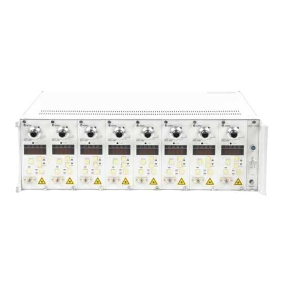
Page 12: Configuration
WAVELENGTH EXTERNAL CAVITY TUNABLE LD MODULE ECL-200 LD.If PD.Im TEMP FINE SELECT DOWN 1 ECL-200 mainframe 1 unit RF.IN OPT.OUT 2 Operation Manual (this document) 1 copy 3 Test Data 1 copy Artisan Technology Group - Quality Instrumentation ... Guaranteed | (888) 88-SOURCE | www.artisantg.com... - Page 13 ECL-200 OPERATION MANUAL Artisan Technology Group - Quality Instrumentation ... Guaranteed | (888) 88-SOURCE | www.artisantg.com...
-
Page 14: Specifications
ECL-200 EXTERNAL CAVITY TUNABLE LD MODULE Specifications (Standard Specifications) Guaranteed value Representative value [ Wavelength ] Center wavelength 1550±10nm 1550nm ( Wavelength ) Tuning range > 70nm 100nm ( Wavelength ) Tuning resolution Rough adjustment : 100±5GHz (About 0.8nm) 100±5GHz (About 0.8nm) Fine adjustment : 0.01nm... - Page 15 ECL-200 OPERATION MANUAL Artisan Technology Group - Quality Instrumentation ... Guaranteed | (888) 88-SOURCE | www.artisantg.com...
-
Page 16: Principle Of Operation
The oscillation wavelength of ECL-200 is controlled by OBPF and OGF. Rough adjustment of oscillation wavelength may be carried out by tuning wavelength of OBPF at every OGF grid interval (about 100 GHz) (by the manual rotating table). - Page 17 ECL-200 OPERATION MANUAL Artisan Technology Group - Quality Instrumentation ... Guaranteed | (888) 88-SOURCE | www.artisantg.com...
-
Page 18: Safety Notes And Safety Devices
1) In the case of use on the power rack MLS-8000 It is necessary to turn OFF the main switch of the power rack MLS-8000. 2) In the case of use in single unit of ECL-200 It is necessary to disconnect the external power cord. (Refer to Chapter 6.) In the event of any of the following, make sure that the injection current of LD is 0, turn OFF the main switch, and then disconnect the power cord. - Page 19 ECL-200 OPERATION MANUAL Artisan Technology Group - Quality Instrumentation ... Guaranteed | (888) 88-SOURCE | www.artisantg.com...
-
Page 20: Installation
MLS-8000. 6-2. In the case of use in single unit of ECL-200 ECL-200 may be used as a single unit by connecting external power source to the I/O connector (D-sub 25P) at the rear panel of the mainframe. - Page 21 CAUTION Mistake in connecting cable may cause failure. 6-2-2. Cable Connection Connect the ECL-200 mainframe and external power source by use of the produced connection cable. NOTE As external power source to be used, use a series power source with small noise for Å}8V supply.
-
Page 22: Descriptions Of Panel Equipment
11 10 (1) Fixing screw This is the fixing screw to be used when to load ECL-200 onto the power source rack MLS-8000. (2) Wavelength setting dial Turning this dial enables rough adjustment of wavelength. (Refer to Chapter 8.) The division of the dial is optional, and is not correlated with the actual wavelength tuning amount. - Page 23 ECL-200 OPERATION MANUAL (5) Numeric value display board Set value / monitor value of the mode indicated on the mode indication LED is displayed. When the mode indication LED currently selected flickers, set value is displayed, while it is lit on, monitor value is displayed.
-
Page 24: Rear Panel
• Descriptions of Rear Panel Equipment I/O connector I/O connector (D-sub 25P) Connection terminal for ECL-200 power supply and communication (RS-232C). I/O connector pin sign 1 Analog power input 2 Digital power input Artisan Technology Group - Quality Instrumentation ... Guaranteed | (888) 88-SOURCE | www.artisantg.com... - Page 25 ECL-200 OPERATION MANUAL Artisan Technology Group - Quality Instrumentation ... Guaranteed | (888) 88-SOURCE | www.artisantg.com...
-
Page 26: Functions Of This Unit
Functions of This Unit Wavelength Tuning Function ECL-200, having two wavelength selection elements, an optical band pass filter and an optical grid filter, in its external cavity, has 2 kinds of wavelength tuning functions by controlling respective wavelength selection elements. -
Page 27: Coherence Control
ECL-200 OPERATION MANUAL Coherence Control In external cavity LD, oscillated spectral line width is largely contracted compared with normal semiconductor. Spectral line width is one of the factors to determine light coherence, and the narrower the spectral line width, the more improved the coherence. Optical fiber may be said the most excellent propagation path from the viewpoints of optical mode, loss, and so on. -
Page 28: Fundamental Operation
1) In the case on power source rack MLS-8000 Turn ON the main switch of the power source rack MLS-8000. If power is supplied to ECL-200 mainframe, each temperature control (LD, optical GF environmental temperature) starts. In this unit, current is not supplied to LD while power is supplied. -
Page 29: Driving Ld
ECL-200 OPERATION MANUAL 9-2. Driving LD 9-2. Driving LD Turning ON/OFF the current to LD is carried out by the LD drive key at the front panel. CAUTION Before turning ON/OFF the power to the mainframe and switching ACC/APC, be sure to shut off the current supply to LD. -
Page 30: Operation In Each Mode
ECL-200 EXTERNAL CAVITY TUNABLE LD MODULE 9-4. Operation in each mode 9-4. Operation in each mode Switching each mode (LD.lf, PD.im, TEMP, FINE mode) is made by use of the mode SELECT key at the front panel. At this moment, selected mode is displayed on the mode display LED. - Page 31 ECL-200 OPERATION MANUAL Example 1) Setting the LD input current to 100.0 mA (1) Turn OFF the LD drive key. (2) Select ACC by the ACC/APC switching key. (3) Turn ON the LD drive key. (4) Select the LD.lf mode by the mode SELECT key.
-
Page 32: Coherence Control
ECL-200 EXTERNAL CAVITY TUNABLE LD MODULE 9-5. Coherence Control 9-5. Coherence Control Turning ON/OFF the coherence control is carried out by use of the mode SELECT key. Pressing the mode SELECT key over 3 seconds causes the coherence control to get ON. -
Page 33: Setting Wavelength
Therefore, when the optical grid filter is fixed and the selection wavelength of the optical band pass filter is changed by adjusting the wavelength setting dial, the transmission wavelength of ECL-200 varies by the wavelength grid interval of the optical grid filter (100 GHz). This is the rough adjustment function of wavelength. -
Page 34: Rough Adjustment Function Of Transmission Wavelength
The rough adjustment function of wavelength is carried out by the wavelength setting dial at the front panel. Turning this dial causes the wavelength of ECL-200 to vary between grids of the optical grid filter inside. Turning the dial to the right (clockwise) causes the wavelength to change to long wavelength side, while turning it to the left (counterclockwise) causes the wavelength to change to the short wavelength side. - Page 35 LD. Temp =25 ºC LD. Temp =23 ºC Procedures (1) Monitor the light output of ECL-200 by use of an optical wavelength meter or an optical spectrum analyzer. (2) Turn the wavelength setting dial to set it to your desired wavelength (at this moment, setting wavelength resolution is grid interval of optical GF).
-
Page 36: Fine Adjustment Of Transmission Wavelength
FIG. Adjustment of optical grid filter by FINE mode How to adjust By use of the wavelength setting dial, adjust the wavelength of ECL-200 adjacent to the target wavelength. Move the position of the wavelength grid by adjusting FINE mode, and adjust the wavelength of ECL-200 to the target wavelength. - Page 37 Procedures (1) Monitor the light output of ECL-200 by use of an optical wavelength meter or an optical spectrum analyzer. (2) Turn the wavelength setting dial to set it to your desired wavelength.
-
Page 38: How To Set Transmission Wavelength Of Ecl-200
ECL-200 EXTERNAL CAVITY TUNABLE LD MODULE 9-6-3. How to set transmission wavelength of ECL-200 * LD injection current is constant. Start LD temperature stable? Change the wavelength between grids by the wavelength setting dial. Make the light output maximum in identical wavelength by finely adjusting the wavelength setting dial. -
Page 39: How To Shut Power Off
When to shut power off, be sure to shut off the current supplied to LD. If power is shut off while current is supplied to LD, LD may be damaged. 2) In the case of use as single unit of ECL-200 Press the LD drive key to shut off the injection current to LD. -
Page 40: Communication
RS-232C of ECL-200 employs the most simple 3-line communication method. When to connect it to a computer, connect TDX to the receive line of ECL-200, connect RDX to the send line of ECL-200, and connect ground line to SG, and short-circuit 4 terminals RTS, CTS, DSR, and CD at computer side. - Page 41 ECL-200 outputs "NR". It always confirms echo back and controls to make communication of command and data precise. To take out data from ECL-200, command for takeout without data of echo back is prepared. Delimiter may be set to CR, LF, CR/LF.
-
Page 42: 10-3.Communication Control
2 alphabetical letters after sending command irrespective of data presence or absence. (DI and SU commands are exceptions.) The command and format of data are shown below: (1) Command of 2 alphabetical letters to ECL-200 (2) Data in the case when data is added to command, or expanded portion of command 10-3... - Page 43 Then it sends non echo back command "DI" for data request, and when data is requested, the data of the command that has been executed is selected and output. ECL-200 outputs the current data at data request until the next output data change command is received.
- Page 44 3) Status The status of ECL-200 is represented by a code and 6-digit 0 or 1. Status can be taken out by communication SU command, and each status may be confirmed by the display panel and LED on the front panel.
-
Page 45: 10-4.Sample Program
ECL-200 OPERATION MANUAL 10-4 Sample Program Here is a sample program written in N88BASIC by NEC-9800 series. This program steps the injection current from 0 to 150 mA in unit of 1 mA, and reads the monitor current value. This program assumes that all the required communication conditions such as delimiter are already set. -
Page 46: Maintenance
ECL-200 EXTERNAL CAVITY TUNABLE LD MODULE Maintenance Daily Maintenance As for daily maintenance, turn the unit off, disconnect the power source cord, and wipe the unit with dry and soft cloth. Do not use any chemical (acetone, alcohol, liquid cleanser). Otherwise, painting may be damaged. - Page 47 ECL-200 OPERATION MANUAL 11-2 Artisan Technology Group - Quality Instrumentation ... Guaranteed | (888) 88-SOURCE | www.artisantg.com...
-
Page 48: Long-Term Storage
ECL-200 EXTERNAL CAVITY TUNABLE LD MODULE Long-term Storage Here are some instructions on long-term storage of this product. NOTE Recycling the packing materials will help repackage this product, so keep the packing materials. Notes before Storage 1) Wipe away dust, dirt, finger print, other stain on this product. - Page 49 ECL-200 OPERATION MANUAL 12-2 Artisan Technology Group - Quality Instrumentation ... Guaranteed | (888) 88-SOURCE | www.artisantg.com...
-
Page 50: Troubleshooting
Santec Photonics Laboratories. Our telephone number and facsimile number are shown below. - Page 51 ECL-200 OPERATION MANUAL 13-2 Artisan Technology Group - Quality Instrumentation ... Guaranteed | (888) 88-SOURCE | www.artisantg.com...
- Page 52 Artisan Technology Group is your source for quality new and certified-used/pre-owned equipment SERVICE CENTER REPAIRS WE BUY USED EQUIPMENT • FAST SHIPPING AND DELIVERY Experienced engineers and technicians on staff Sell your excess, underutilized, and idle used equipment at our full-service, in-house repair center We also offer credit for buy-backs and trade-ins •...
Need help?
Do you have a question about the ECL-200 and is the answer not in the manual?
Questions and answers