Table of Contents
Advertisement
Bulletin 949-1194
INSTRUCTIONS FOR THE 2600 SERIES
MICROPROCESSOR BASED
TEMPERATURE /PROCESS CONTROL
LOVE CONTROLS
LOVE
a Division of Dwyer Instruments, Incorporated
PO Box 338
Michigan City, IN 46361-0338
®
H
(800) 828-4588
(219) 879-8000
FAX (219) 872-9057
H
H
www.love-controls.com
May, 2013
Page 1 of 52
949-1194 Rev. 7
GlobalTestSupply
www.
.com
uality Products Online at:
sales@GlobalTestSupp
Advertisement
Table of Contents

Related Manuals for Love Controls 2600 SERIES

Summary of Contents for Love Controls 2600 SERIES
- Page 1 Bulletin 949-1194 INSTRUCTIONS FOR THE 2600 SERIES MICROPROCESSOR BASED TEMPERATURE /PROCESS CONTROL LOVE CONTROLS LOVE a Division of Dwyer Instruments, Incorporated PO Box 338 Michigan City, IN 46361-0338 ® (800) 828-4588 (219) 879-8000 FAX (219) 872-9057 www.love-controls.com May, 2013 Page 1 of 52 949-1194 Rev.
-
Page 2: Table Of Contents
DIMENSIONS ............50 © 2001, Love Controls. All rights reserved. No portion may be copied without the express written consent of Love Controls. -
Page 3: Getting Started
GETTING STARTED Install the control as described on page 5. Wire your control following the instructions on pages 5-11. If you are using a two- wire transmitter as an input, see the drawing and instructions on page 7. Option wiring instructions are on pages 8-11. Option descriptions and specific instructions start on page 19. -
Page 4: Model Identification
995 RS-232 Serial Communications, Modbus protocol. ® 996 RS-485 Serial Communications, Modbus protocol. ® Lovelink™, Lovelink™II, and Mother Node™ are Trademarks of Love Controls. MODBUS is a trademark of Schneider Automation. ® May, 2013 Page 4 of 52 949-1194 Rev. 7 GlobalTestSupply www. -
Page 5: Installation
INSTALLATION Mount the instrument in a location that will not be subject to excessive temperature, shock, or vibration. All models are designed for mounting in an enclosed panel. Select the position desired for the instrument on the panel. If more than one instrument is required, maintain the minimum of spacing requirements as shown on the drawing below. -
Page 6: Input Wiring
For supply connections use No. 16 AWG or larger wires rated for at least 75°C. Use copper conductors only. All line voltage output circuits must have a common disconnect and be connected to the same pole of the disconnect. Input wiring for thermocouple, current, and RTD; and output wiring for current and 15 VDC is rated CLASS 2. -
Page 7: Output Wiring
OUTPUT WIRING Wire outputs as shown in the chart below. Terminals SP1 SSR SP1 15 VDC SP1 Relay SP1 Current SP2 SSR SP2 15 VDC SP2 Relay SP2 Current Key: ‘+’ = positive; ‘-’ = negative; ‘NC’ = Normally Closed; ‘NO’ = Normally Open; ‘C’ = Common. -
Page 8: Wiring For Optional Inputs And Outputs
WIRING FOR OPTIONAL INPUTS AND OUTPUTS All wiring shown below is Class 2. Shielded twisted pair is required for Options 992 and 996. Shielded cable is required for Options 993 and 995. Options 924, 926, and 928 share a common ground with input. CAUTION: DO NOT RUN SIGNAL WIRING IN THE SAME CONDUIT OR CHASE AS THE POWER WIRING. -
Page 9: Wiring For Option 928 Remote Set Point
CAUTION: DO NOT RUN SIGNAL WIRING IN THE SAME CONDUIT OR CHASE AS THE POWER WIRING. ERRATIC OPERATION OR DAMAGE TO THE CONTROL CIRCUITRY WILL RESULT. WIRING FOR OPTION 928 REMOTE SET POINT Option 928 Option 928: Input 0 to 10 kohms, 4µA Search Current WIRING FOR OPTION 934 ANALOG RETRANSMISSION Option 934: Output 0 to 20 mADC,... -
Page 10: Wiring For Option 948 4-Stage Set Point
CAUTION: DO NOT RUN SIGNAL WIRING IN THE SAME CONDUIT OR CHASE AS THE POWER WIRING. ERRATIC OPERATION OR DAMAGE TO THE CONTROL CIRCUITRY WILL RESULT. WIRING FOR OPTION 948 4-STAGE SET POINT SWITCH CONTACTS FOR OPTION 948 MUST BE ISOLATED AND CAN NOT SHARE WIRING WITH OTHER CONTROLS. -
Page 11: Wiring For Option 992, 993, 995, 996 Serial Communications
CAUTION: DO NOT RUN SIGNAL WIRING IN THE SAME CONDUIT OR CHASE AS THE POWER WIRING. ERRATIC OPERATION OR DAMAGE TO THE CONTROL CIRCUITRY WILL RESULT. WIRING FOR OPTION 992, 993, 995, 996 SERIAL COMMUNICATIONS Options 992, 996 DIP Switch Positions* Half Duplex* Full Duplex 1 2 3 4 5 6... -
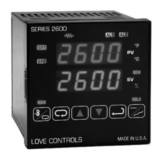
Page 12: Front Panel Key Functions
FRONT PANEL KEY FUNCTIONS Alarm 1 Lamp Heater Fail Lamp Alarm 2 Lamp Set Point 1 Lamp °F Indicator Set Point 2 Lamp °C Indicator Process Display Remote Set Lamp Set Point Display Percent Lamp Manual Indicator The decimal point flashes when Self Tune is operating. INDEX: Menu Navigation. -
Page 13: Password Table
A L i H : Alarm inhibit O P E n I n P : Input error message b A d I n P : Input error message C H E C C A L : Check calibration error Correct the problems associated with the above conditions before using these reset keys. More than one error could be present. -
Page 14: Notation Conventions For The Menus
NOTATION CONVENTIONS FOR THE MENUS Because of the number of features available in this control, information is included that may not apply to your specific control. All usable features are included in this book, but may not be used in your process. To increase clarity the following conventions are used: 1. -
Page 15: The Home Display
Theory of Operation The 2600 Series controls offer a very simple approach to programming a ramp. Rather than requiring the operator to calculate an approach rate (usually in degrees per minute), the 2600 does the calculation internally. Thus, the operator only needs to program the target set point and the time desired to reach that point. - Page 16 Soaks (or dwells) are ramp segments where the target set point is the same as the beginning process value. This allows for multistage ramps without wasting intermediate soak steps. Care must be taken, however, that the process does actually reach the soak value before the soak time starts.
- Page 17 The last menu item for the ramp / soak function is P E n d . P E n d determines what the control does when the program has ended. You may choose to have the program repeat (L o o P ), H o l d the last set point (1 6 S P ), revert to the local S P 1 , or turn the outputs off (O o F F ).
-
Page 18: Auto / Manual Operation
Self Tune allows automatic selection of the necessary parameters to achieve best control operation from your 2600 Series control. If you are using the control output as a simple on-off function (O u t 1 set for O n O F ), none of the following will apply. -
Page 19: Operation And Programming Of Options
Program Setup and Operation Do not cool the process or add heat while the tuning is occurring. In the secondary menu set t u n E to S E L F . Skip L E r n and check to make sure that d F A C is set to the desired value. Back up to L E r n and set to Y E S . -
Page 20: Option 934, 936, Isolated Analog Retransmission
Option 934, 936, Isolated Analog Retransmission. The analog retransmission option allows the Process Variable or the Set Variable to be sent as an analog signal to an external device. The signal may be either 0 to 10 VDC (Option 936) or 0 (or 4) to 20 mADC (Option 934). The output may be changed in the field from one to the other by the toggle switch located on the top printed circuit board. -
Page 21: Option 948, 4-Stage Set Point
Option 948, 4-Stage Set Point. The 4-stage set point option allows four different values to be used for S P 1 and all of the values associated with the t u n E menu items. The control will switch to a given stage when an external contact or contacts are made or opened across the appropriate terminals at the rear of the control (S P S A , Set Point Switch Action, set for remote, r E ), or when the stage is selected from the Secondary Menu, S P (when S P S A is set for I n t ). -
Page 22: Serial Communications Options And Nonvolatile Memory
This is the type of memory that Love Controls uses to save the settings you program in your control. The reliability and longevity of the data retention is what allows us to guarantee a 10 year data retention without power. -
Page 23: Menu Selections
Adding one of the computer communications options (e.g. 992, 993, 995, 996) changes the picture. The speed of computer communications is such that hundreds of instructions can be made in less than a minute. In such a situation, the million erase / write cycles could be used up in a couple of months causing the chip (and the control) to fail. -
Page 24: Secondary Menu
SECONDARY MENU Hold UP ARROW & ENTER. Press INDEX to advance to the next menu item. Press UP ARROW or DOWN ARROW to change the value in the display. Press ENTER to retain the value. If your instrument is not equipped with alarms (third character of part number is ‘0’), the Secondary Menu starts with O u t 1 , below. - Page 25 # # t P Time Proportioning Cycle Time. Select 1 t P to 8 0 t P . A setting of 1 t P is recommended for solid state outputs (SSR or 1 t P 15 VDC). 2 t P to 8 0 t P Time Proportioning Control is adjustable in 1 second steps.
- Page 26 # P u L Pulsed Time Proportioning Output: Select 1 P u L to 7 P u L . 1 P u L = Linear and 7 P u L = most nonlinear. Changes output linearity for use in cooling applications or for extremely fast response processes.
- Page 27 Damping factor, Select O F F , 1 to 7. Sets the ratio of Rate to d F A C Reset for the S E L F t u n E mode. 7 = most Rate. Factory set to 3. For a fast response process the value should be lowered (less Rate).
- Page 28 Approach Rate Time: Select O F F , 0 . 0 1 to 9 9 . 9 9 minutes. The function defines A r t E the amount of Rate applied when the input is outside of the Proportional Band. The A r t E time and the r t E time are independent and have no effect on each other.
- Page 29 Ramp/Soak: Select O n or O F F P r o 9 Allows Programmed Ramp/Soak function to be started by the Run/Hold key on the control front panel. Turns Ramp/Soak function O F F and resets program to beginning. O F F Programmer function set: Select O n or O F F .
- Page 30 Input Correction: Select - 5 0 0 to 0 to 5 0 0 °F, °C, or counts. This feature allows I n P C the input value to be changed to agree with an external reference or to compensate for sensor error. Note: I n P C is reset to zero when the input type is changed, or when decimal position is changed.
-
Page 31: Secure Menu
(Option 992, 993, 995, 996, Serial Communications) Local / Remote Status: L O r E Select L O C or r E . Does not affect other instruments on daisy chain. The host computer is advised that remote write commands will be L O C rejected. - Page 32 Input Type: Select one of the following. Refer to the Wiring section for the proper I n P wiring. Type “J” Thermocouple J - I C Type “K” Thermocouple Type “E” Thermocouple Type “T” Thermocouple Type “L” Thermocouple Type “N” Thermocouple Type “R”...
- Page 33 Input Fault Timer: Select O F F , 0 . 1 to 5 4 0 . 0 minutes. Whenever an Input is out of I n P t range (U F L or O F L displayed), shorted, or open, the timer will start. When the time has elapsed, the controller will revert to the output condition selected by I n P b below.
- Page 34 If O u t 1 (Page 19) is set for # # t P , # P U L , or P r o P , then S 1 O L and S 1 O H appear. If O u t 1 is set for O n O F , then skip to S 1 r E .
- Page 35 If your control is not equipped with Set Point 2, then proceed to the alarm section (next page). Set Point 2 type: Select A b S or d E . S 2 t Absolute S P 2 . S P 2 is independent of S P 1 , and may be set anywhere A b S between the limits of S P L and S P H .
- Page 36 Set Point 2 Reset. Select O n O F or H o l d . S 2 r E Output will automatically reset when process passes back through O n O F S P 2 d . Manual Reset. Reset (acknowledge) by simultaneously pressing the H o l d INDEX &...
- Page 37 The diagram below shows the action and reset functions for both absolute and deviation alarms. D = 1 degree F, 1 degree C, or 1 count. Note that when Alarm Power Interrupt, A 1 P i , is programmed O n and Alarm Reset, A 1 r E , is programmed for H o l d , the alarm will automatically reset upon a power failure and subsequent restoration if no alarm condition is present.
- Page 38 If A L 1 is set to O F F goto A L 2 (next page). If A L 1 is set to E U n t , go to A 1 S t below. Alarm 1 Type: Select A b S or d E A 1 t Absolute Alarm that may be set anywhere within the values of S C A L A b S...
- Page 39 If A L 2 is set to O F F and the control is not equipped with options, the Secure Menu ends here. If A L 2 is set to O F F and the control is equipped with options, proceed to S P S A , A d d r , or r S C L below.
- Page 40 (Option 948, 4-Stage Set Point) Switch Action: Select r E or I n t . S P S A Set Point Stage selected by external contact closures. Set Point Stage selected by internal menu selection. See S P menu item I n t in Secondary Menu.
-
Page 41: Error Messages
ERROR MESSAGES Any error message may be cleared by using the ‘Global Reset’ by pressing and holding the INDEX & ENTER keys for five seconds. Display Meaning SP Outputs Action Required This message appears Set point Correct the ambient temperature A r E A (Alternates if the ambient outputs... - Page 42 ERROR MESSAGES Any error message may be cleared by using the ‘Global Reset’ by pressing and holding the INDEX & ENTER keys for five seconds. Display Meaning SP Outputs Action Required Underflow or Overflow: Set point May be normal if Input signals go U F L Process value has outputs...
- Page 43 ERROR MESSAGES Any error message may be cleared by using the ‘Global Reset’ by pressing and holding the INDEX & ENTER keys for five seconds. Display Meaning SP Outputs Action Required Display is blank. Set point Check that the power supply is on, display Instrument is not getting outputs...
-
Page 44: Configuration Menu
CONFIGURATION MENU DO NOT ENTER THE CONFIGURATION MENU UNLESS YOU HAVE BEEN INSTRUCTED TO BY THESE INSTRUCTIONS. INCORRECT ENTRY OF DATA IN THE CONFIGURATION MENU MAY CAUSE IMPROPER OR UNPREDICTABLE OPERATION OF THE INSTRUMENT. The Configuration Menu is used to quickly recover the instrument after certain Error Codes. - Page 45 Press INDEX to C n F 1 . Press INDEX to A c P t . If you do not want to retain the re-confi guration, this is your last chance to return to the old confi guration. Press ENTER at A c P t n o to exit and retain the old configuration.
-
Page 46: Specifications
SPECIFICATIONS Selectable Inputs: Thermocouple, RTD, DC Voltage, or DC Current selectable. Input Impedance: Thermocouple = 3 megohms minimum. RTD current = 200 μA. Current = 10 ohms. Voltage = 5000 ohms. Sensor Break Protection: De-energizes control output to protect system after customer set time. - Page 47 Control Output Ratings: SSR: 2.5 A @ 240 Vac at 25°C (77°F). Derates to 1.25 A @ 55°C (130°F); Relay: SPDT, 10 A @ 240 VAC resistive; 1/2 hp @ 120 VACor 1/3 hp @ 240 VAC; Alarm Relay: SPST, 3 A @ 240 VAC resistive; 1.5 A @ 240 VAC inductive. Pilot Duty Rating: 240 VA, 2A @ 120 VAC or 1A @ 240 VAC.
- Page 48 Termination: 120 Ohms, balanced. Number can be increased through use of a repeater such as the Mother Node™. Consult factory for details. Lovelink™, Lovelink™II, and Mother Node™ are Trademarks of Love Controls. MODBUS ® is a trademark of Schneider Automation.
-
Page 49: Input Ranges
INPUT RANGES INPUT TYPE RANGE °F RANGE °C Type J or L Thermocouple -100 to +1607 -73 to +871 Type K Thermocouple -200 to +2500 -129 to +1371 Type T Thermocouple -350 to +750 -212 to +398 Type E Thermocouple -100 to +1800 -73 to +982 Type R Thermocouple 0 to 3200... -
Page 50: Dimensions
Meets IP66 (UL Type 4X) All dimensions are in millimeters with inches in parenthesis. Panel cutput for all models is 92mm x 92mm (3.625in x 3.625in). Allow for 13mm (0.5in) clearance at the rear of the instrument. May, 2013 Page 50 of 52 949-1194 Rev. - Page 51 May, 2013 Page 51 of 52 949-1194 Rev. 7 GlobalTestSupply www. .com uality Products Online at: sales@GlobalTestSupp...
- Page 52 May, 2013 Page 52 of 52 949-1194 Rev. 7 GlobalTestSupply www. .com uality Products Online at: sales@GlobalTestSupp...
Need help?
Do you have a question about the 2600 SERIES and is the answer not in the manual?
Questions and answers