
Related Manuals for Amsco 3085 SP

Summary of Contents for Amsco 3085 SP
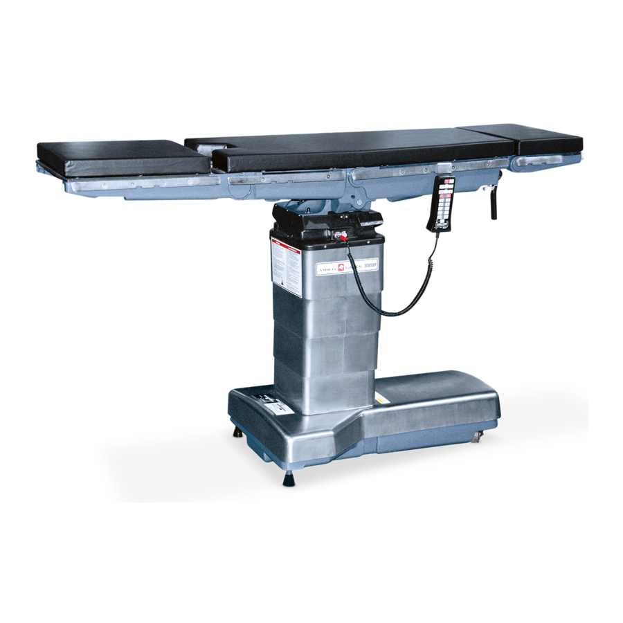
- Page 1 OPERATOR MANUAL 3085 SP Surgical Table Amsco ® (10/01/04) P150830-026...
-
Page 2: A Word From Steris Corporation
These instructions are important to protect the health and safety of personnel operating a 3085 SP table and should be retained in a conveniently accessible area for quick reference. Complete instructions for uncrating have been furnished. If missing, contact STERIS for a replacement copy, giving the serial and model numbers of the unit. - Page 3 EC Authorized Representative STERIS Limited STERIS House Jays Close Viables Basingstoke Hampshire RG22 4AX UNITED KINGDOM Manufactured by: STERIS Corporation 2720 Gunter Park East Montgomery, AL 36109 • USA Class 1 Equipment Type B Equipment Ordinary Equipment (enclosed equipment without protection of ingress of water).
-
Page 4: Table Of Contents
3.1 Install and Route Power Cord ..................3-2 3.2 Install Hand Control and Lock Table in Place .............. 3-3 3.2.1 Standard 3085 SP Tables Hand Control ..............3-3 3.2.2 Operating Room Control System (ORCS) Hand Control ........3-3 3.2.3 Lock Table in PLace ..................... 3-4 3.3 Hand Control Interchangeability .................. - Page 5 TABLE OF CONTENTS (Cont'd) Section Title Page 5 AUXILIARY OVERRIDE SYSTEMS ..........5-1 5.1 Articulation With Electric Pump Power Available ............5-2 5.2 Articulation With No Electric Pump Power Available ............ 5-3 5.3 Floor Lock Override Systems ..................5-3 6 ROUTINE MAINTENANCE ............... 6-1 6.1 Preventive Maintenance Schedule ................
-
Page 6: Safety Precautions
STERIS tables must not be used for reverse orientation on the 3085 SP Table. Do not use two or more Uro-Endo/Image Amplification Extension accessories together on the 3085 SP Table. Do not articulate table with auxiliary override systems unless floor locks are engaged. - Page 7 WARNING – PERSONAL INJURY HAZARD: Healthcare professionals must ensure patients are positioned and monitored to prevent compromising respiration, nerve pathways, or circulation. When installing any table accessory, check for correct attachment and tighten securely (if appropriate). Do not use worn or damaged accessory. Check installation before using any accessory. There is a 1,000-lb (452-kg) patient weight limit if patient is in normal orientation and a 500-lb (226-kg) patient weight limit if patient is in reversed orientation;...
- Page 8 -Ready or ACT Enabled™ 3085 SP hand control with the blue strain relief on the plug. The standard 3085 SP hand control has a red strain relief on the plug. These two hand controls are not interchangeable. Hang the hand control from side rail (or end rail) of the table when not in use, to avoid possible damage to the control.
- Page 9 Following is a key to symbols which may be on your table or controls. Definition of Symbols Symbol Definition Protective Earth (Ground) Attention, Consult Manual for Further Instructions Amperage Rating of the Unit Voltage Rating of the Unit Alternating Current Power Rating of the Unit Frequency of the Unit Equipotentiality...
- Page 10 Symbol Definition Floor Lock (Function Touch Pad) Floor Lock: Lock Floor Lock: Unlock Patient Orientation (Function Touch Pad) Normal Orientation Reverse Orientation Trendelenburg Reverse Trendelenburg Height Up (Raise) Height Down (Lower) Tilt Left Tilt Right Back Up Back Down Leg Up Leg Down Continued ...
- Page 11 Symbol Definition Flex Reflex Level 150830-026 Operator Manual Safety Precautions...
-
Page 12: Important User Information
Figure 2-1 before operating the table. ® The Amsco 3085 SP™ Surgical Table is designed to safely support a 1,000-lb 2.2 Patient (452-kg) patient in the normal orientation only with limited posturing, or a 500-lb (226-kg) patient in the reversed orientation. - Page 13 Typical Pinch Point and Tipping Hazard When Lowering Between Column Skirt and Column Cap Between Ratchet Handle and Table Frame Between Kidney Bridge and Tabletop or Between Kidney Bridge and X-ray Set Column Column Skirt Between Saddle and Table Frame Between Table Frame and Column Skirt Between Headrest (if...
-
Page 14: Prevent Possible Tipping
(For up to 500-lb [226-kg] Patient Weight) • Foot Extension Accessory or combination of Foot Extension and Headrest Accessories from previous design STERIS tables must not be used for reverse orientation on the 3085 SP Table. Important User Information Operator Manual 150830-026... -
Page 15: Other Considerations
Do not exceed the ac- cessory load rating if it is lower than the table rating. Amsco 3085 SP Surgical Tables are remote control, Image Amplification 2.3 General compatible units with auxiliary override (backup) systems for the control and hydraulic systems. -
Page 16: Technical Specifications
2.4 Technical Specifications 2.4.1 Overall Size 24-13/32 x 75-15/16 x 27 to 44" (WxLxH) (620 x 1,928 x 686 to 1,118 mm) 737 lbs (334 kg); maximum anticipated floor lock pressure exerted on floor: 2.4.2 Weight 380 psi (2,619 KPa) with a 500-lb (226-kg) patient load, 440 psi (3,033 KPa) with a 1,000-lb (452-kg) patient load. -
Page 17: Installation Instructions
INSTALLATION INSTRUCTIONS NOTE: Patient grounding post/potential equalization terminal (male connector, WARNING – PERSONAL DIN 42801) is provided. Mating female connector is not furnished by STERIS. INJURY HAZARD: If the integ- IMPORTANT: Before connecting the table to your AC power system, check rity of the external protective that table internal voltage switches are set for your power system (100, 120, 220, earth conductor installation... -
Page 18: Install And Route Power Cord
ARD: Route the power cord to it into an appropriate receptacle. the receptacle in a position 4. For either electric-powered or battery-powered 3085 SP, power cord may so it will not be tripped over remain plugged into appropriate receptacle indefinitely. It will not harm table by personnel in the area. -
Page 19: Install Hand Control And Lock Table In Place
EQUIPMENT DAMAGE: • For ORCS equipped tables, use the HERMES ® -Ready ACT Enabled 3085 SP hand control with the blue strain Align Red Dots to Connect relief on the plug. The stan- Hand Control Plug dard 3085 SP hand control has a red strain relief on the plug. -
Page 20: Lock Table In Place
3.2.3 Lock Table in Place 1. Press ON button at top of hand control to turn table on. All LEDs on hand control may light momentarily for control system self-test when power is turned on. Refer to Figure 3-4 for identification of hand control functions. See S ECTION , to identify any problems with the hand control. -
Page 21: Hand Control Interchangeability
• The 3080 RC hand control will plug into and operate the 3080 RL, 3080 SP, and 3085 SP in a normal fashion EXCEPT there is no Return-to-Level button. CAUTION – POSSIBLE EQUIPMENT DAMAGE: The • The 3080 RL, 3080 SP, and 3080 RL/SP/3085 SP hand control will plug into and ® HERMES -Ready... -
Page 22: Operating Instructions
OPERATING INSTRUCTIONS For maximum patient positioning flexibility, the Amsco ® 3085 SP™ Surgical 4.1 Attach Headrest Table is designed so the headrest can be attached to either end of the table. and Orient Patient IMPORTANT: Control must be oriented as to the patient's position on table before any positioning functions are operable. - Page 23 3. Press ORIENT PATIENT Function button in center row of buttons on hand WARNING – TIPPING control and within five seconds (while LED is still lit), press appropriate HAZARD: Actuate button (NORMAL or REVERSE) to indicate orientation of patient's • Do not use this table for pa- head on table (see Figures 4-2 and 4-3).
-
Page 24: Tabletop Positioning
The tabletop may be articulated within the limits shown by use of the hand 4.2 Tabletop control positioning buttons or the optional foot control positioning pedals, or by the optional ORCS System. If these controls fail to function, refer to S Positioning ECTION , to see if the problem can be quickly determined and corrected. - Page 25 Adjust the tabletop position by using the hand control positioning buttons, as follows (see Figure 4-3): 1. Press FLOOR LOCK Function button in center row of buttons on hand control and within five seconds (while LED is still ON), press desired Actuate button (LOCK or UNLOCK) adjacent to it.
-
Page 26: Optional Foot Control Operation
2) When a normal patient load exceeds 700 lb (318 kg), moving the table from an extreme Right Tilt may require the tabletops be level. When normal patient load exceeds 900 lb (408 kg), moving the table from an extreme Right Tilt may be slow or not operate. - Page 27 2. Connect foot control assembly to table by aligning foot control cord gray plug WARNING – TIPPING red dot with table gray receptacle red dot, and pushing plug into connected HAZARD: During an articula- position (see Figure 4-5). tion if the tabletop sections NOTE: For foot control, note the following: contact an obstruction, the table may tip.
-
Page 28: Care Of Controls When Not In Use
• Lower Height – 27" (686 mm) minimum. Depress right side of HEIGHT pedal (located in the center position of foot control pedals) and release pedal when desired position has been reached to automatically stop tabletop and lock it in position. •... -
Page 29: Optional Operating Room Control System (Orcs) Operation
IMPORTANT: Use the HERMES-Ready 3085 SP hand control with the blue WARNING – PERSONAL strain relief.The standard 3085 SP hand control with a red strain relief tail on the INJURY HAZARD: Unantici- connector will not connect to the HERMES-Ready table. For proper HERMES... -
Page 30: Act Enabled System Operation
IMPORTANT: Use the ACT Enabled 3085 SP hand control with the blue strain relief.The standard 3085 SP hand control with a red strain relief tail on the connector will not connect to the ACT Enabled table. For proper ACT voice/touch panel operation, ensure ACT Enabled table is interfaced with the appropriate Operating Room Control System. -
Page 31: Headrest Positioning
The headrest can be attached to either end of table (see Figure 4-1). Headrest 4.4 Headrest is manually adjustable 90° upward and 90° downward from horizontal position. Adjust the headrest to desired position as follows: Positioning 1. See Figure 4-8. Locate release handle (under right side of headrest) and pull to release (spring-loaded). -
Page 32: Pads And Accessories
A four-section X-ray top accessory is available from STERIS for use with Amsco 4.6.2 X-ray Top Accessory 3085 SP tables (see Figure 4-12). Each of the top sections has two types of standoff spacers. The shorter spacers rest on the tabletop; the longer, spring- loaded spacers (which secure the X-ray top) fit into tabletop mounting holes. -
Page 33: General Accessories Applied To Side Rails
Perform the following for each X-ray top section: Spring Clip Projecting Short Standoff Beyond Standoff 1. Loosen screws securing spring-loaded spacers to X-ray top section. Position section on table. 2. Rotate spacers so spring clips are in line when viewed from beneath tabletop (see Figure 4-13). -
Page 34: Accessories Specific To Amsco 3085 Sp Tables
• Perineal Cutout Filler – attaches to tabletop to cover cutout and provide additional patient support. (Limited to 400-lb [181 kg] patient load.) For application of other STERIS table accessories to your Amsco 3085 SP table, contact STERIS. 4-13... - Page 35 (Shown Without X-Ray Top and 2" [51 mm] Pad) Drain Tray 3080/3085 Orthopedic Extension Neuro Seat Plate Figure 4-15. Accessories* for Amsco 3085 Tables *Contact STERIS for ordering information. Refer to specific accessory descriptions for weight limitations. 4-14 150830-026 Operator Manual...
-
Page 36: Auxiliary Override Systems
AUXILIARY OVERRIDE SYSTEMS The Amsco ® 3085 SP™ Surgical Table is equipped with Auxiliary Override WARNING – EXPLOSION Systems that can be actuated at any time and that will allow table operation in HAZARD: Table must not be the event of primary control malfunction. -
Page 37: Articulation With Electric Pump Power Available
A row of toggle switches (located on the top of column under the small hood, 5.1 Articulation With on the opposite side from the hand control connection; see Figure 5-1) is used for table movements if control power is still available. Electric Pump Power Available Articulate table as follows:... -
Page 38: Articulation With No Electric Pump Power Available
The toggle switches (or hand/foot control selections) are used in conjunction 5.2 Articulation With with the foot pedal for table movements when no electric pump power is available. No Electric Pump Power Available Articulate table as follows: 1. Flip foot pedal down (see Figure 5-2). 2. -
Page 39: Routine Maintenance
Contact STERIS for the proper oil to use. ® Table 6-1. Preventive Maintenance Schedule for Amsco 3085 SP™ Surgical Table SERVICE REQUIRED MINIMUM FREQUENCY PREPARATION FOR PREVENTIVE MAINTENANCE Discuss equipment with operators. - Page 40 Table 6-1. Preventive Maintenance Schedule for Amsco 3085 SP Surgical Table (Cont'd) SERVICE REQUIRED MINIMUM FREQUENCY CONTROLS Verify proper operation of all articulations for full motion. • Using hand control. 6x per year • Using override function. 6x per year •...
-
Page 41: Cleaning/Disinfecting Procedures
1. Remove gross soil with a disposable cloth and place used cloth in an 6.2 Cleaning/ appropriate biohazardous waste disposal container. Disinfecting 2. Clean tabletop as follows: Procedures a. Articulate tabletop to level position and place at a comfortable working height. -
Page 42: End-Of-Day
3. Raise table to maximum elevation to access lower surfaces. CAUTION – POSSIBLE 4. Clean column skirt, cap, and shrouds, and entire base surface as follows: EQUIPMENT DAMAGE: a. Holding can 6-8" (150-200 mm) from surface, spray cleaning fluid liberally •... -
Page 43: Biweekly Maintenance
1. Charge batteries per instructions listed in S 6.5.1, B ECTION ATTERY HARGING 6.3 Biweekly ROCEDURE Maintenance NOTE: Battery-powered tables should have batteries charged a minimum of 38 hours every two weeks (more often if table usage demands). 2. Operate each table function. Operation should be smooth and quiet. WARNING –... -
Page 44: Battery Charging Procedure
• It is not necessary to have hand control ON to charge batteries. age. Contact STERIS regard- ing service options. • On either electric-powered or battery-powered 3085 SP, power cord may be left plugged into appropriate receptacle indefinitely. It will not harm table nor WARNING – TRIPPING table batteries. - Page 45 2. Allow a minimum of 48 hours for full battery charge. See chart below: Charging Time Portion Charge 24 hours 90 percent 36 hours 95 percent 48 hours 100 percent 3. Verify low battery indicator LED is off and disconnect AC power. 4.
-
Page 46: Troubleshooting
TROUBLESHOOTING This section describes the types of Amsco ® 3085 SP™ Surgical Table WARNING – PERSONAL malfunctions most likely to occur, and probable causes and corrective actions. INJURY AND/OR EQUIPMENT Use the Operator Troubleshooting Chart to identify general problems. Use the... - Page 47 Hand Control Diagnostics Chart NOTE: When power supplies are operational and the table is plugged into an AC receptacle, the ON touch pad green LED and AC power green LED will be ON. INDICATION CONDITION CORRECTIVE ACTION 1. Control ON – green AC AC power connected;...
- Page 48 ® 2. Check the control: The HERMES -Ready ACT Enabled ™ hand controls have an 18-pin connector and will not fit the standard 3085 SP Table. 3. If plug or receptacle is deformed, it must be replaced. NOTE: For troubleshooting of the optional HERMES ®...
-
Page 49: Service Procedures
The material in this section is provided to allow for servicing components of the WARNING – PERSONAL Amsco ® 3085 SP™ Surgical Table most likely to need attention. These INJURY AND/OR EQUIPMENT procedures are more advanced than cleaning and replacing expendables. DAMAGE HAZARD: Repairs... -
Page 50: Change Fuses
Two replaceable fuses (F1 and F2) are located in a cartridge above the AC input in the table base. If one or both of the fuses are blown by a fault condition, 8.2 Change Fuses replace as follows: 1. Disconnect AC power cord from wall receptacle and table base input (see Figure 8-2). -
Page 51: Replacement Parts
The parts listed in Table 8-1 may be necessary to do minor maintenance on the Amsco 3085 SP Table. 8.4 Replacement Parts To order replacement parts, proceed as follows: 1. Include part number and description listed in Table 8-1. 2. Include model and serial numbers of your equipment on your order. - Page 52 Table 8-1. Amsco 3085 SP Surgical Table Replacement Parts Description Part Number Recommended Spares One spare of the type you use. If Power Cord Types Available your plug is not in this list, order • USA Plug, USA Cord P93909-354 the Power Cord type nearest to •...
-
Page 53: Disposal Hazards
DISPOSAL HAZARDS The following materials are contained within the Amsco ® 3085 SP™ Surgical WARNING – DISPOSAL HAZ- Table. When disposing of the table or its parts, ensure the proper disposal of ARD: This product contains hazardous and other regulated waste in compliance with federal, state, and materials which may require local regulations.
Need help?
Do you have a question about the 3085 SP and is the answer not in the manual?
Questions and answers