Table of Contents
Advertisement
Quick Links
Advertisement
Table of Contents
Troubleshooting

Related Manuals for Panasonic NN-GF668M


Summary of Contents for Panasonic NN-GF668M
-
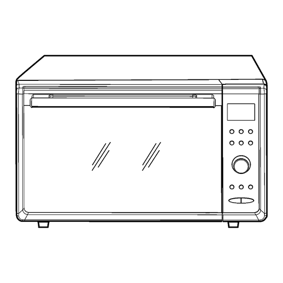
Page 1: Microwave Oven
ORDER NO.PHAMO0806026C2 Microwave Oven NN-GF668M EPG (Continental Europe) SPG (Norway, Finland, Sweden, Denmark) © 2008 Panasonic Home Appliances Microwave Oven (Shanghai) Co., Ltd. All rights reserved. Unauthorized copying and distribution is a violation of law. - Page 2 NN-GF668M...
- Page 3 NN-GF668M...
-
Page 4: Table Of Contents
NN-GF668M CONTENTS Page Page 1 FEATURE CHART 7 COMPONENT TEST PROCEDURE 2 CONTROL PANEL 7.1. Primary, Secondary Latch Switch interlocks & Power 3 SCHEMATIC DIAGRAM Relay RY1 4 DESCRIPTION OF OPERATING SEQUENCE 7.2. Short Switch 4.1. Variable power cooking control 7.3. -
Page 5: Schematic Diagram
NN-GF668M 1 FEATURE CHART 2 CONTROL PANEL... -
Page 6: Description Of Operating Sequence
NN-GF668M 4 DESCRIPTION OF OPERATING SEQUENCE 4.1. Variable power cooking 4.3. Auto Weight cooking control When the Auto Weight feature is selected and the [Start] button is pressed: High Voltage Inverter Power Supply (U) controls output power 1. The digital programer circuit determines the power level and by the signal from Digital Programmer Circuit (D.P.C.). -
Page 7: Cautions To Be Observed When Troubleshooting
NN-GF668M 5 CAUTIONS TO BE OBSERVED WHEN TROUBLESHOOTING Unlike many other appliances, the microwave oven is a high voltage, high current device. It is free from danger in ordinary use, though extreme care should be taken during repair. CAUTION Servicemen should remove their watches and rings whenever working close to or replacing the magnetron. -
Page 8: Part Replacement
NN-GF668M 5.6. Verification after repair Discharging the high voltage capacitors WARNING 1. After repair or replacement of parts, make sure that the There is high voltage present with high current capabilities screws of the oven, etc. are neither loose or missing. -
Page 9: Disassembly And Parts Replacement Procedure
NN-GF668M 6 DISASSEMBLY AND PARTS REPLACEMENT PROCEDURE 6.1. Magnetron 7. Remove 1 screw holding thermistor on magnetron. 1. Discharge the high voltage capacitor (see page 8 for instructions). 2. Remove screws holding inverter reinforcement/grounding bracket A on oven cavity. 8. Remove 2 screws holding air guide A on magnetron, then remove air guide A. -
Page 10: Digital Programmer Circuit (D.p.c) Au, (D.p.c.) Du, Membrane Sheet, Low Voltage Transfarmer And Power Relay
NN-GF668M 12. Release locking tabs of inverter reinforcement/grounding 4. Forcibly pull out rotary dial directly. bracket A hanging on both sides of oven cavity, then withdraw the inverter reinforcement/grounding bracket A outside slightly. NOTE: Pay attention to the sharp edges of inverter reinforcement/grounding bracket A. -
Page 11: Inverter
NN-GF668M 7. Remove 3 screws holding grounding panel on escutcheon 2. When installing the new membrane sheet, make sure base. that the surface of escutcheon base is clean. 6.3. H.V. Inverter 8. Remove 11 screws holding D.P.C. board AU (display &... -
Page 12: Fan Motor
NN-GF668M 6.4. Fan motor 12. Release catch hook from Inverter bracket A. 1. Disconnect 2 lead wires from fan motor terminals. 2. Remove 4 screws holding air guide B on magnetron & on base plate respectively, then remove air guide B. -
Page 13: Upper Heaters
NN-GF668M 6.5. Upper heaters 6.6. Door assembly 1. Disconnect lead wires from both sides of upper heaters. 1. Remove left and right door key springs from door arm with plier. 2. Remove 2 screws holding heater support from the right side of microwave oven. -
Page 14: Stirrer Motor
NN-GF668M 6.7. Stirrer motor NOTE: Do not remove the two screws holding the left and 1. Remove the motor cover by breaking off at the 8 spots right hinges on the bottom of cavity front plate. indicated by arrows with a cutter or the like. -
Page 15: Component Test Procedure
NN-GF668M 7 COMPONENT TEST PROCEDURE WARNING 7.3. Magnetron 1. High voltage is present at the output terminals of the High Voltage Inverter (U) including aluminum heat sink during any cook cycle. Continuity checks can only indicate an open filament or a 2. -
Page 16: Inverter Power Supply (U)
NN-GF668M 7.4. Inverter power supply (U) 5. Program oven at High power for 1 minute and press [Start] button. DO NOT try to REPAIR H.V. Inverter power supply (U). a. After approximately 3 seconds, oven stops operating. Replace complete H.V. Inverter(U) Unit. -
Page 17: Measurements And Adjustments
NN-GF668M 8 MEASUREMENTS AND ADJUSTMENTS 8.1. Adjustment of Primary latch 4. The Primary latch switch must be ON when the space between upper portion of door A and cavity front plate is switch, Secondary latch 2~4mm, if the door gap is greater than 4mm, the Primary switch and Short switch. -
Page 18: Troubleshooting Guide
NN-GF668M 9 TROUBLESHOOTING GUIDE DANGER: HIGH VOLTAGES 1. DO NOT RE-ADJUST PRESET CONTROL on the H.V.Inverter (U). It is very dangerous to repair or adjust without proper test equipment because this circuit generates very large current and high voltage. Operating a misaligned inverter circuit is dangerous. -
Page 19: Troubleshooting) Oven Stops Operation During Cooking
NN-GF668M 9.1. (Troubleshooting) Oven stops operation during cooking SYMPTOM CAUSE CORRECTIONS 1. Oven stops in 3 seconds after No input AC is supplied to H.V.Inverter (U) 1. Latch Switch pressing [Start] button. CN702 terminals 2. Power relay RY1 3. Loose lead wire connector CN701, CN702 4. -
Page 20: Troubleshooting) Other Problems
NN-GF668M 9.2. (Troubleshooting) Other problems SYMPTOM CAUSE CORRECTIONS 1. Oven is dead. 1. Open or loose lead wire harness Check thermal cutout is defective. Fuse is OK. 2. Open thermal cutout / thermistor No display and no operation at all. -
Page 21: Troubleshooting Of Inverter Circuit (U) And Magnetron
NN-GF668M 9.3. Troubleshooting of inverter circuit (U) and magnetron This oven is programmed with a self diagnostics failure code system which will help for troubleshooting. H95, H97, H98 and H99 are the provided failure codes to indicate magnetron and inverter circuit problem areas. This section explains failure codes of H95, H97, H98 and H99. -
Page 22: Trouble Related To Digital Programmer Circuit
NN-GF668M 9.4. Trouble related to Digital Programmer Circuit SYMPTOM STEP CHECK RESULT CAUSE/CORRECTIONS →Step2 No display when oven is first plugged Fuse pattern of D.P.C. Normal Open Replace D.P.C. or Fuse Pattern Low voltage transforment (L.V.T.) Abnormal 0V L.V.T. secondary voltage →Step3... -
Page 23: How To Check The Semiconductors Using An Ohm Meter
NN-GF668M 9.6. How to check the semiconductors using an OHM meter 9.7. H.V. INVERTER MAIN PARTS LIST (Z606Y6Y40BP) Ref. No. Part No. Part Name & Description Pcs/Set Remarks Q701 TRANSISTOR SI A691E4V10GP Q702 TRANSISTOR SI DB701 AESTRS2006M DIODE SI 20A,600V...
Need help?
Do you have a question about the NN-GF668M and is the answer not in the manual?
Questions and answers