Advertisement
Table of Contents
- 1 Table of Contents
- 2 Warning Decal Placement
- 3 Important Precautions
- 4 Before You Begin
- 5 Assembly
- 6 Operation and Adjustment
- 7 How to Fold and Move the Treadmill
- 8 Troubleshooting
- 9 Exercise Guidelines
- 10 Part List
- 11 Exploded Drawing
- 12 Ordering Replacement Parts
- 13 Recycling Information
- Download this manual
Model No. PETL60707.0
Serial No.
USER'S MANUAL
Write the serial number in the space
above for future reference.
Serial Number
Decal
QUESTIONS?
As a manufacturer, we are commit-
ted to providing complete customer
satisfaction. If you have questions,
or if there are missing parts, please
contact us at the numbers or ad-
dresses listed below:
Call: 08457 089 009
Outside UK: 0 (44) 113 3877133
Fax: 0 (44) 113 3877125
E-mail: csuk@iconeurope.com
Write:
ICON Health & Fitness, Ltd.
Unit 4
Revie Road Industrial Estate
Revie Road, Beeston
Leeds, LS11 8JG
UK
CAUTION
Read all precautions and instruc-
tions in this manual before using
this equipment. Save this manual
for future reference.
Advertisement
Table of Contents

Subscribe to Our Youtube Channel
Related Manuals for Pro-Form PETL60707.0


Summary of Contents for Pro-Form PETL60707.0
- Page 1 Model No. PETL60707.0 Serial No. USER'S MANUAL Write the serial number in the space above for future reference. Serial Number Decal QUESTIONS? As a manufacturer, we are commit- ted to providing complete customer satisfaction. If you have questions, or if there are missing parts, please...
-
Page 2: Table Of Contents
TABLE OF CONTENTS WARNING DECAL PLACEMENT ............. .2 IMPORTANT PRECAUTIONS . -
Page 3: Important Precautions
IMPORTANT PRECAUTIONS WARNING: To reduce the risk of serious injury, read all important precautions and in- structions in this manual and all warnings on your treadmill before using your treadmill. ICON as- sumes no responsibility for personal injury or property damage sustained by or through the use of this product. - Page 4 21. When folding or moving the treadmill, make maintenance and adjustment procedures de- sure that the storage latch is fully closed. scribed in this manual. Never remove the motor hood unless instructed to do so by an 22. Inspect and properly tighten all parts of the authorized service representative.
-
Page 5: Before You Begin
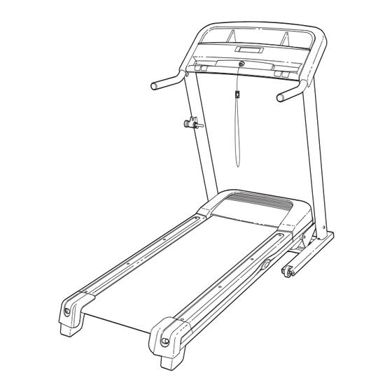
BEFORE YOU BEGIN Thank you for selecting the new PROFORM ® STYLE using the treadmill. If you have questions after read- 6500 treadmill. The STYLE 6500 treadmill combines ad- ing this manual, please see the front cover of this man- vanced technology with innovative design to help you ual. -
Page 6: Assembly
ASSEMBLY Assembly requires two persons. Set the treadmill in a cleared area and remove all packing materials; do not dispose of the packing materials until assembly is completed. Note: The underside of the treadmill walking belt is coated with high-performance lubricant. During shipping, a small amount of lubricant may be transferred to the top of the walking belt or the shipping carton. - Page 7 1. Make sure that the power cord is unplugged. Attach a Wheel (95) to each side of the Base (37) with a 3/8" x 3" Bolt (5), two Wheel Spacers (94), and a 3/8" Nut (31) as shown. Do not overtighten the wheel Bolts;...
- Page 8 4. See the left inset drawing. Identify the two Frame Spacers (96). Apply some of the included grease to both sides of the Frame Spacers. Next, identify the outer side of each Frame Spacer. Hold a Frame Spacer (96) and a Frame Washer (99) between the Right Upright (39) and the Lift Frame (41), with the outer side of the Frame Spacer facing the Frame Washer and the...
- Page 9 6. Set the Console (68) face down on a soft sur- face to avoid scratching the Console. Hold the Right Handrail (40) near the Console as shown. Console Insert the console wire into the large hole on the Wire side of the Right Handrail and out the hole on top as shown.
- Page 10 8. Next, finger tighten four M8 x 15mm Bolts (9) with four M8 Handrail Star Washers (11) into the Right and Left Handrails (40, 70). Then, tighten all four handrail Bolts. 9. Have a second person raise and hold the tread- Cylinder mill Frame (36).
- Page 11 10. Pivot the cylinder end of the Gas Spring (83) down to the position shown. Remove the Spring Clip Kit (90) from the end of the Gas Spring. Next, align the cylinder end of the Gas Spring (83) with the bracket in the center of the Base (37).
- Page 12 12. Attach the ground wire on the Upright Wire (69) to the indicated hole in the Base (37) with a #8 x Grommet 1/2" Silver Screw (10). Press the indicated grommet into the Right Upright (39). Hole Ground Wire 13. Carefully raise the Uprights (38, 39). Attach the Latch Housing (91) to the Left Upright (38) with two #8 x 3/4"...
-
Page 13: Operation And Adjustment
OPERATION AND ADJUSTMENT THE PRE-LUBRICATED WALKING BELT Your treadmill features a walking belt coated with high-performance lubricant. IMPORTANT: Never apply sili- cone spray or other substances to the walking belt or the walking platform. Such substances will deterio- rate the walking belt and cause excessive wear. HOW TO PLUG IN THE POWER CORD This product must be earthed. - Page 14 CONSOLE DIAGRAM Clip Note: If there are thin sheets of plastic on the console, remove the plastic. FEATURES OF THE CONSOLE Plug in the power cord (see page 13). Next, locate the Reset The treadmill console offers a selection of features reset/off circuit breaker on Position designed to make your workouts more effective.
- Page 15 HOW TO USE THE MANUAL MODE 4. Change the incline of the treadmill as desired. 1. Insert the key into the console. To change the incline of the treadmill, press the Incline increase and decrease buttons. Each time See HOW TO TURN ON THE POWER on page you press a button, the incline setting will change by 0.5%;...
- Page 16 The upper display can To measure your heart rate, stand on the foot show the distance that rails and place your hands on the metal contacts— avoid moving your hands. When your pulse is de- you have walked or run, the approximate number tected, the heart symbol in the display will begin to of calories you have...
- Page 17 HOW TO USE A PRESET WORKOUT cline setting is programmed for the next segment, the speed or incline setting will flash in the display 1. Insert the key into the console. to alert you. See HOW TO TURN ON THE POWER on page The workout will continue in this way until the last segment of the profile flashes in the display and the last segment ends.
- Page 18 THE INFORMATION MODE switch the reset/off circuit breaker to the reset position, and insert the key into the console. However, when The console features an information mode that keeps you remove the key, the displays will remain lit, al- track of treadmill usage information and allows you to though the buttons will not function.
-
Page 19: How To Fold And Move The Treadmill
HOW TO FOLD AND MOVE THE TREADMILL HOW TO FOLD THE TREADMILL FOR STORAGE Before folding the treadmill, adjust the incline to the lowest position. If you do not do this, you may permanently damage the treadmil. Next, unplug the power cord. CAUTION: You must be able to safely lift 45 lbs. - Page 20 HOW TO LOWER THE TREADMILL FOR USE 1. Hold the treadmill with your right hand as shown. Pull the latch knob to the left and hold it. Pivot the frame down until it is past the latch pin. Latch Knob Latch Pin 2.
-
Page 21: Troubleshooting
TROUBLESHOOTING Most treadmill problems can be solved by following the steps listed below. Find the symptom that ap- plies, and follow the steps listed. If you need further assistance, please see the front cover of this manual. PROBLEM: The power does not turn on SOLUTION: a. - Page 22 Locate the Reed Switch (59) and the Magnet (98) on the left side of the Pulley (84). Turn the Pulley until the Magnet is aligned with the Reed Switch. Make 3 mm sure that the gap between the Magnet and the Reed Switch is about 3 mm (1/8 in.).
-
Page 23: Exercise Guidelines
EXERCISE GUIDELINES Burning Fat—To burn fat effectively, you must exer- WARNING: cise at a low intensity level for a sustained period of Before beginning this time. During the first few minutes of exercise, your or any exercise program, consult your physi- body uses carbohydrate calories for energy. -
Page 24: Part List
PART LIST—Model No. PETL60707.0 R0607A Key No. Qty. Description Key No. Qty. Description 3/8" x 2 3/4" Bolt Left Rear Foot 1/4" Washer Right Rear Foot #8 x 3/4" Screw Reed Switch 3/8" x 2 1/4" Bolt Lift Motor 3/8" x 3" Bolt Drive Motor 3/8"... -
Page 25: Exploded Drawing
EXPLODED DRAWING A—Model No. PETL60707.0 R0607A... - Page 26 EXPLODED DRAWING B—Model No. PETL60707.0 R0607A...
- Page 27 EXPLODED DRAWING C—Model No. PETL60707.0 R0607A...
-
Page 28: Ordering Replacement Parts
ORDERING REPLACEMENT PARTS To order replacement parts, please see the front cover of this manual. To help us assist you, be prepared to pro- vide the following information when contacting us: • the model number and the serial number of the product (see the front cover of this manual) •...
Need help?
Do you have a question about the PETL60707.0 and is the answer not in the manual?
Questions and answers