J-Series Data Radio – User Manual Contents Part F – Quick Reference Guide Introduction Part A – Preface Mounting and Installation Instructions Physical Dimensions - Remote Ethernet Data Radio Warranty Connecting Antennas and RF Feeders Important Notice J-Series Connections Layout FCC Compliance Notices Power Supply Requirements Australian Compliance Notices...
Trio DataCom Pty Ltd or to such other place as Trio DataCom RF Exposure Pty Ltd shall nominate. Following repair or replacement the To satisfy FCC RF exposure requirements for mobile transmitting equipment shall be returned to the customer freight forward.
Page 4
Händler in Verbindung, von dem Sie ursprünglich das locations and may void the approval. Produkt kauften. 5. A power connector with locking screws as supplied by Trio Low Voltage Safety (Europe) Datacom MUST be used. WARNING EXPLOSION HAZARD In order to comply with the R&TTE (Radio &...
The TRIO J-Series comprises of the following models: • ChannelShare™ collision avoidance for unsolicited remote transmissions allowing simultaneous polling and - the JR900, which operates within the 915MHz license spontaneous reporting free frequency band (country specific models apply), * Up to 140km (90 miles) single repeater system range with...
Page 6
• Network wide access from any radio modem • Over-the-air reconfiguration & diagnostics • Powerful system commissioning and troubleshooting tools • Compatible with Trio TVIEW+ Diagnostics for stand alone network management. • Local and Remote field upgradeable firmware Securing your network through Trusted Access Control: •...
= O Series configured for J Series Options 2 = No Options = Hazardous Environment Class 1, Div 2 (Standard on JR900, KR900 & OM900) = ATEX II 3G, Ex nA IIC T4 compliance (Standard on JR240, KR240 & OM240) Options 1 = Diagnostics (Inc.
J-Series Data Radio – User Manual Part B – J-Series Overview Standard Accessories RF Cables and Accessories Part Number Description RFCAB5M2 5.0m RG-213 type Antenna Feeder Cable Antennas terminated with N type Male Connectors ANT9AL Antenna Yagi 6 Element 9dBd Alum 850- RFCAB10M 10.0m RG-213 type Antenna Feeder Cable 930MHz...
J-Series Data Radio – User Manual Part C – Network Types Part C – Network Types Introduction Fundamental to understanding the use of J-Series Ethernet Data Radios in your system is the need for a basic understanding of the different types of radio network topologies (known as NETWORK TYPES) and the function of each radio within them (known as RADIO TYPES).
J-Series Data Radio – User Manual Part C – Network Types Point-to-Multipoint Networks (PTMP) A Point to Multipoint (PTMP) network is normally chosen when one site (i.e.: The HOST) needs to broadcast messages to multiple REMOTE sites. Point to Multipoint (PTMP) operation requires the Access Point site to have adequate RF coverage of all Remote sites which need to synchronize to the Access Point.
J-Series Data Radio – User Manual Part C – Network Types Point-to-Multipoint via KwikStream™ Repeater A Point to Multipoint via KwikStream™ Repeater network is a variation of the Point To Multipoint network. It is normally chosen when the site where the SCADA (i.e.: data) entry point does not have adequate RF coverage of other Remote sites in the network.
Point to Point with LinkXtend™ Bridge (PTP/B) The typical range of the Point to Point (PTP) Network Type can be extended using the Trio Datacom unique dual antenna LinkXtend™ technology. This is achieved using a special radio mode called BRIDGING. A dual antenna LinkXtend™ bridge allows the maximum range possible from a single radio store and forward technology whilst remaining within legal antenna EIRP limits.
J-Series Data Radio – User Manual Part C – Network Types Point to Multipoint via LinkXtend™ Bridge (PTMP/B) Note: It is recommended that you first read Part C - Point to Multipoint (PTMP) Networks and Part C - Point to Point with LinkXtend™ Bridges before reading this section.
J-Series Data Radio – User Manual Part D – Features Features Useful for Optimizing The choice of radio data rates will depend on the level of RF Performance. signal strength, but will also depend on other factors like RF noise. In general, higher RF signal levels are required when using the In addition to the settings made to establish Radio Type, Network 512kbps RF data date, otherwise an unreliable link may result.
Page 15
J-Series Data Radio – User Manual Part D – Features Hopping Intervals Frequency Hopping Spread Spectrum (FHSS) radios like the J-Series operate in an unlicensed shared frequency band and collisions can be expected when multiple radios are operating in the same area. Due to the hopping nature of the radio, the radio “hops”...
J-Series Data Radio – User Manual Multi-Access Point Synchronization Access Points each have the same hop interval and each hop interval begins at the same time (as synchronised by the primary When more than one J-Series network shares the same physical Access Point), no Access Point will transmit when the others are in site (i.e: antennas for each network are in close proximity) receive mode.
J-Series Data Radio – User Manual Digital Collision Avoidance Retries and Retransmissions ChannelShare™ No Ack Retries In some network applications there exists the potential for over the Data transmitted from a REMOTE to an Access Point is air data collisions between REMOTE radios. This can occur when acknowledged by the Access Point.
As such they are always enabled. Unlike 802.11 and WiFi equipment which can be purchased “off the shelf” the Trio J-Series employs many levels of defence against Peer to Peer Repeat Filtering: security potential security threats.
Page 19
J-Series Data Radio – User Manual Part D – Features Encryption When encryption is enabled in a network, all data sent over the air is protected from eavesdropping and can only be read by radios sharing the same Encryption Key. Encryption must be enabled in each radio in a network.
J-Series Data Radio – User Manual Part D – Features SmartPath™ The J-Series radio provides unique features to enhance connectivity and redundancy in both fixed and mobile applications. Typical SCADA and Telemetry systems require a high degree of radio link reliability. Using SmartPath™ features together with a small amount of system planning, the system designer can create a network topology that provides for multiple alternative radio link paths.
Page 21
J-Series Data Radio – User Manual SmartPath™, Network Name & Hopping Patterns A fundamental rule of all J-Series radios (remotes or bridges) is that they will only synchronise to networks which have a matching Network Name. When implementing a network with Bridges, each section of the Network is broken up into smaller “SubNets” which is described in Part C of this User Manual.
Page 22
J-Series Data Radio – User Manual Part D – Features SmartPath™ and Preferred/Alternative Access Points SmartPath™ allows system designers to create redundant connection paths that help to negate single point failures. Consider the PTMP network shown below. In this network, the system designer requires that Remote radios quickly re-synchronize to an alternative Access Point should the preferred Access Point no longer be accessible.
Page 23
J-Series Data Radio – User Manual SmartPath™ PTMP using LinkXtend™ Bridges SmartPath™ allows the user to create multiple redundant connection paths in complex PTMP systems using LinkXtend™ bridges. Consider the PTMP with LinkXtend™ network shown below. The system designer requires that each unit synchronises to the network as quickly as possible, even if the topology is not initially the preferred one.
Page 24
J-Series Data Radio – User Manual SmartPath™ and Roaming Remotes SmartPath™ allows the user to design networks that permit Remote radios to roam. In a roaming network, a remote is typically installed on a moving vehicle or object, such as a truck or a train. Access Point radios are installed at key locations where good RF coverage can be provided. The desired outcome is for connectivity to any available Access Point.
Page 25
J-Series Data Radio – User Manual SmartPath™ and Hybrid Networks SmartPath™ allows the system designer additional flexibility to create a redundant backbone based on preferred and alternative paths while deploying remote radios where no configuration is required. This is shown in the network diagram below. Two Access Points are installed to provide redundancy at the Access Point radio level.
SNMP facilities include RFC1213 as well as radio and Ethernet diagnostics. Trio Datacom supply .MIB files that can be imported into most major SNMP agents. These .MIB files define the contents of the SNMP parameters including a description for each parameter.
J-Series Data Radio – User Manual Spectrum Analyzer and Channel Text User Interface (TUI) Lockout Facility As of firmware release V3.1, the J-Series radios provide a text user interface which can be accessed via Telnet and Serial connections. As of firmware release V3.1, the J-Series radios support a The text user interface (TUI) provides an alternative mechanism for spectrum analysis and channel lockout facility.
J-Series Data Radio – User Manual Legacy Serial Support Differences between TCP and UDP TCP is a Point to Point (PTP) connection-oriented protocol, which The serial port device servers provide transparent encapsulation over IP (IP tunnelling) of RS-232 serial data . It redirects raw serial means that upon communication it requires connection overhead to set up and maintain the end-to-end connection.
Page 29
J-Series Data Radio – User Manual Legacy Serial Modes Supported Point to Point via TCP/IP: This mode of operation provides a reliable point to point connection between two units (based on the IP address). When only two units need serial connectivity in a PTP arrangement and latency and bandwidth are not a major concern, the TCP IP mode should be selected.
Page 30
J-Series Data Radio – User Manual Part D – Features Point to Multi-Point via UDP/IP: This mode of operation provides a point to multi-point connection between multiple units (based on the IP address). This mode of operation uses UDP/IP Multicasting and suitable Multicasting IP address ranges should be used. Refer to Part G of this User Manual for more information. Point to Multi-Point with Peer to Peer via UDP/IP: This mode of operation provides a point to multi-point connection between multiple units (based on the IP address) with peer to peer connectivity.
J-Series Data Radio – User Manual Part E – RF Planning & Design Part E – RF Planning and Design Understanding RF Path Obstructed Radio Path Requirements This path has an obstruction that will seriously degrade the signal arriving at the field site. A radio modem needs a minimum amount of received RF signal to operate reliably and provide adequate data throughput.
J-Series Data Radio – User Manual Antennas Effect of Earth Curvature on Long Paths This path requires greater mast height to offset the earth curvature There are basically two types of antennas – omni-directional and experienced at such a distance (73km). directional.
J-Series Data Radio – User Manual Part E – RF Planning & Design RF Feeders and Protection Antenna Placement The antenna is connected to the radio modem by way of an When mounting the antenna, it is necessary to consider the RF feeder.
J-Series Data Radio – User Manual Part F – Quick Reference Guide Introduction Welcome to the Quick Start Guide for the 
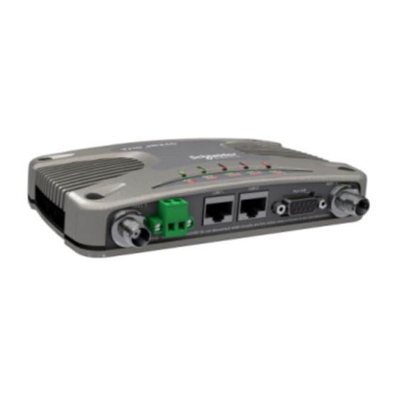
J-Series Ethernet Radio. This guide provides step-by-step instructions, with simple explanations to get you up-and-running. For a summary of this information, please refer to the J-Series Quick Start Guide. Page 34 Issue 09-10...
J-Series Data Radio – User Manual Part F – Quick Reference Guide Mounting and Installation Instructions The radio should be mounted in a clean and dry location, protected from water, excessive dust, corrosive fumes, extremes of temperature and direct sunlight. In high power or high temperature applications, please allow sufficient passive or active ventilation. To avoid moisture ingress mount the radio with the connectors facing downwards.
30V dc or if reverse polarity is applied. The replaceable internal fuse has a rating 3 Amp. Fuse: Trio Part No. SM%FUSSQ3A The current requirement is typically 180mA @ 13.8 V DC in receive mode, and will vary in transmit mode according to RF output power level & duty cycle.
J-Series Data Radio – User Manual Part F – Quick Reference Guide Communication Ports LAN 1 and LAN 2 Ethernet Ports The LAN 1 and LAN 2 ports are 10/100 Base-T compliant ports using an RJ-45 connector. These ports support both TIA/EIA- 568-A &...
J-Series Data Radio – User Manual Part F – Quick Reference Guide Serial Port A & B Ports The J-Series Radio features a 9 pin miniature D-Shell (DE- 9) Female connector that supports two individual serial port connections. Each serial port is associated with an embedded serial terminal server that provides the RS-232 to TCP/IP or UDP/ IP connectivity.
J-Series Data Radio – User Manual Part F – Quick Reference Guide LED Indicators (1) Pwr/TX - DC Power & TX LEDs If all the LEDs are off, no DC power is reaching the radio modem or the internal fuse is open. Successful power-up is indicated by the Pwr/Tx LED showing a continuous GREEN state for Remotes or an alternating Red/Green for Access Points.
J-Series Data Radio – User Manual Part F – Quick Reference Guide J-Series Configuration (Web Interface) Introduction Please read the following notes carefully. Configuration errors with Ethernet connections can be difficult to find and resolve. It is strongly recommended that you follow these guidelines. Factory Default Reset The factory default IP address of the J-Series is 192.168.2.15...
J-Series Data Radio – User Manual Part F – Quick Reference Guide Scroll Down and Select “Internet Protocol (TCP/IP) and then click on Properties. You will now see the window as shown. Ensure “Obtain IP Address Automatically” is not selected. It is recommended that you manually specify a compatible IP Address.
Page 42
J-Series Data Radio – User Manual Part F – Quick Reference Guide Repeated connections to multiple devices with same IP address A common problem experienced when attempting to configure multiple radios with the same IP address (such as factory default radios). The problem is due to invalid MAC table entries.
J-Series Data Radio – User Manual Part F – Quick Reference Guide Multi Master Synchronisation When operating two Access Points in Multi-master synchronization mode (Refer to Part D of this user manual for more information on this feature), the Access Point radios must have the correct configuration options enabled. The configuration required can be divided into two steps.
J-Series Data Radio – User Manual Part F – Quick Reference Guide Text User Interface (TUI) The text user interface (TUI) provides an alternative to the HTML web interface for configuration and diagnostics. The TUI can be accessed directly from the serial port of the J-Series or via a telnet session. The TUI is enabled on Port A by default as well as Telnet. Access to the TUI via the serial port is useful if you have forgotten the IP address of the radio you are trying to configure or diagnose.
Page 45
J-Series Data Radio – User Manual Part F – Quick Reference Guide Part F – Quick Reference Guide Once the J-Series is connected to your PC via a strait through serial cable, Hyper Terminal can then be started to create a serial communications connection to the TUI.
Page 46
J-Series Data Radio – User Manual Part F – Quick Reference Guide The text user interface can also be accessed via Telnet. This is convenient if you are remotely connected to a J-Series via an Ethernet network. The telnet interface provides high speed access to the text user interface via a “Telnet” session. Most computer operating systems come with integrated Telnet software.
Page 47
J-Series Data Radio – User Manual Part F – Quick Reference Guide Test User Interface (TUI) Options The TUI is divided into three distinct areas : (1) Unit Information - Displays important information about the radio such as serial number, currently configured IP address and firmware pack version identification.
J-Series Data Radio – User Manual Part F – Quick Reference Guide Spectrum Analyzer The Spectrum Analyzer is a facility that allows user to observe interfering signals in the ISM band. In Access Point radios, channels that suffer from high levels of interface can be blocked out of the hopping pattern. The spectrum analyzer can only be accessed via the Text User Interface (TUI). An example of a spectrum analysis sweep is shown below.
Page 49
J-Series Data Radio – User Manual Part F – Quick Reference Guide Using the Channel Lockout Facility To lockout channels using the facility in the text user interface, perform the following steps. (1) Connect to the text user interface of the Access Point. Note: You must be locally connected, either via Telnet or the Serial interface. (2) Browse to the Spectrum Analyser facility.
J-Series Data Radio – User Manual Part F – Quick Reference Guide SNMP As of J-Series Firmware V3.1, SNMP (Simple Network Management Protocol) is supported. The J-Series SNMP Interface supports: •Supports RFC1213 (Unit name, Unit Location, Firmware, Uptime, etc) •Supports Radio and Ethernet Diagnostics (as seen in the HTML Diagnostics overview) •SNMP V1 &...
Page 51
J-Series Data Radio – User Manual Part F – Quick Reference Guide Radio Group: “The operating mode of the radio” “Table of subnet ID’s. If there are two rows in this table then the first row represents the upstream subnet ID and the second row represents downstream subnet ID.
J-Series Data Radio – User Manual eDiagnostics eDiagnostics (also known as eDiags) is a feature of the TVIEW+ Diagnostics software that encapsulates the TVIEW+ Diagnostics protocol in an Ethernet UDP/IP packet. Together with the eDiags server built into each J-Series radio, the user can monitor the J-Series Ethernet radios network using the TVIEW+ Diagnostics software over an Ethernet LAN/WAN.
Page 53
J-Series Data Radio – User Manual This now completes the requirements for configuring eDiags. The operation of eDiags for a typical poll/response diagnostics transaction is as follows: (1) The TVIEW+ Diagnostics software constructs a UDP/IP data gram with a target radio IP & Port numbers extracted from the database. (2) The UDP Datagram is placed onto the LAN/WAN which routes the datagram onto the radio network.
J-Series Data Radio – User Manual Part G – Quick Start Guide Point to Point Ethernet Link Setup Step 3 - Preliminary Configuration This is the sequence of steps required for configuring two J-Series in a point-to-point network. One will be configured as an Access IP Address and Factory Default Point and the other as a Remote.
Page 55
J-Series Data Radio – User Manual Part G – Quick Start Guide Step 4 - Web Browser Connection Step 5 - PTP Wizard Activation Open a web browser and type in the IP address of the J-Series The easiest way to get the a PTP J-Series Ethernet link up and radio (In this case, we type “192.168.2.15”).
Page 56
J-Series Data Radio – User Manual Part G – Quick Start Guide Step 6 - PTP Wizard Activation (Remote) Repeat steps (3) to (6) for the Remote radio. Step 7 - Verify Modem Operation The J-Series Ethernet radio modems are now ready for operation. Allow 15 seconds for the Remote radio to synchronise with the Access Point radio Access Point LEDs...
J-Series Data Radio – User Manual Part G – Quick Start Guide Point to Point - TCP Serial Device Server Setup Guide Introduction Click on Activate Configuration. Point to Point connectivity using the TCP/IP mode of the Once the web browser has activated the new configuration and embedded J-Series terminal servers is useful for PTP (Point to then returned to the Configuration page, the configuration of the Point) serial link requiring high reliability data delivery.
J-Series Data Radio – User Manual Part G – Quick Start Guide Point to Point - UDP (Unicast) Serial Device Server Setup Guide Introduction (f) Ensure the Remote IP Port is configured to be 30010 Point to Point (PTP) connectivity using the UDP mode of the (g) Ensure the Local IP Port is configured to be 30010 embedded J-Series terminal servers is useful for PTP serial links Click on Activate Configuration.
J-Series Data Radio – User Manual Part G – Quick Start Guide Point to Multi-Point - UDP (Multicast) Serial Device Server Setup Guide Introduction (g) Ensure the Remote IP Address is an address from the designated multicast range of IP Addresses, in this example we are Point to Multi-Point (PTMP) connectivity using the UDP mode of using 224.168.1.1 (this is the multi-cast address as configured in the embedded J-Series terminal servers is useful for PTMP serial...
Page 60
J-Series Data Radio – User Manual Part G – Quick Start Guide 3 - RS-232 Final Testing The Point to Multipoint via UDP Serial connectivity is now complete. The RS-232 link can be tested using an RS-232 Serial Packet Test Program such as LinkTest or by connecting your RS-232 application.
J-Series Data Radio – User Manual Part G – Quick Start Guide Point to Multi-Point with Peer to Peer - UDP (Multicast to Multicast) Serial Device Server Setup Guide Introduction (f) Ensure the Local IP Address is an address from the designated multicast range of IP Addresses, in this example we are using Point to Multi-Point (PTMP) with Peer to Peer connectivity using 224.140.1.1 (this is the multi-cast address as configured in the...
Page 62
J-Series Data Radio – User Manual Part G – Quick Start Guide 3 - RS-232 Final Testing The Point to Multipoint via UDP Serial connectivity is now complete. The RS-232 link can be tested using an RS-232 Serial Packet Test Program such as LinkTest or by connecting your RS-232 application.
J-Series Data Radio – User Manual Part H – Installation & Commissioning Introduction POWER CONNECTIONS All Ethernet radio modems need to be properly installed and The power required is: commissioned in order to function reliably. It is important that Tx: Nominal 13.8 Volts DC @ 800 mA (Max 1A) installers are familiar with RF products / installations and are equipped with appropriate tools necessary to ensure the ongoing Rx: Nominal 13.8 Volts DC @ 150 mA...
J-Series Data Radio – User Manual Part H – Installation & Commissioning ANTENNA INSTALLATION Where possible it is important to avoid mounting antennas: The selection of antennas and their placement is one of the most 1. Against or adjacent to steel structures. important factors when installing a radio based network.
J-Series Data Radio – User Manual Part H – Installation & Commissioning Optimizing the Antenna for Rx Signal Access Point: RSSI voltage is only present if it is receiving valid When using a directional antenna, it will be necessary to align data from down stream.
J-Series Data Radio – User Manual Part H – Installation & Commissioning Commissioning Unit Specific: Date: Specifies the current date and time. For the date and When commissioning an Ethernet radio network, it is important time to be correct the radio must be configured to to ensure that the incoming received signal strength (RSSI) is synchronise with a NTP Time Server.
Page 67
J-Series Data Radio – User Manual Part H – Installation & Commissioning When the test is complete, a note stating “Packet error test completed” will be shown and the test results summarized in the “Test Results” section. Access Point The test results show TX & RX Packets, Lost Packets and the Packet Error Rate.
J-Series Data Radio – User Manual Part I – Firmware Updating Firmware Update Overview (R2.x.x or later) Firmware Update Procedure Ensure that an Ethernet patch cable is connected from your LAN Introduction port to either LAN1 or LAN2 of the J-Series, and the correct IP Note: These instructions apply only to J-Series running address is entered into your web browser.
Page 69
J-Series Data Radio – User Manual During this phase, all 5 LED indicators will flash amber Select Upload and once the warning below pops up Click on OK to simultaneously. After 1 to 10 minutes the J-Series will re-boot and confirm you are happy to deleate old firmware.
Antennas not listed in the above table must be tested to comply with FCC Section 15.203 (unique antenna connectors) and Section 15.247 (emissions). Please contact Trio Datacom Inc. if you need more information. Page 70 Issue 09-10...
J-Series Data Radio – User Manual Part K – Support Options Website Information The TRIO Datacom web site support contains links to e-mail and telephone support, technical notes, manuals, software updates. Please go to www.triodatacom.com E-mail Technical Support E-mail your questions to support@triodatacom.com...
The suitability of the enclosure is subject to investigation by the local Authority having jurisdiction at the time of installation. All TRIO Datacom Radios come with a industry leading 3 year Warranty Issue 09-10...
Page 73
You must cause the modified files to carry prominent notices stating that you source code in this product on a CD, TRIO Datacom will mail to You a CD with changed the files and the date of any change.
Page 74
J-Series Data Radio – User Manual may not impose any further restrictions on the recipients’ exercise of the rights Schedule 2 granted herein. You are not responsible for enforcing compliance by third parties If this product contains open source software licensed under the OpenSSL to this License.
Page 75
J-Series Data Radio – User Manual list of conditions and the following disclaimer in the documentation and/or other THIS SOFTWARE IS PROVIDED BY THE COPYRIGHT HOLDERS AND materials provided with the distribution. CONTRIBUTORS ``AS IS’’ AND ANY EXPRESS OR IMPLIED WARRANTIES, INCLUDING, BUT NOT LIMITED TO, THE IMPLIED WARRANTIES OF 3.
Need help?
Do you have a question about the JR900 and is the answer not in the manual?
Questions and answers