
Related Manuals for Trio ER45E


Summary of Contents for Trio ER45E
- Page 1 E Series Ethernet Radio – User Manual E Series Ethernet Radio User Manual ER45e Remote Data Radio EB45e Base Station EH45e Hot Standby Base Station www.triodatacom.com Issue 3: August 2010 Version 08-10 Page 1...
-
Page 2: Table Of Contents
Programmer & Diagnostics Firmware Updating Understanding RF Path Requirements Examples of Predictive Path Modelling Power Supply and Environmental Considerations Physical Dimensions - Remote Data Radio - ER45e Physical Dimensions - ER45e Mounting Cradle/Din Rail Mount (Optional) Mounting Cradle Din Rail Mount (Optional) -
Page 3: Part A - Preface
The warranty does not cover modifications to software. All equipment for repair under warranty must be returned freight paid to TRIO Datacom Pty Ltd or to such other place as TRIO Datacom Pty Ltd shall nominate. Following repair or replacement the equipment shall be returned to the customer freight forward. -
Page 4: Compliance Information
Co-Locating the ER45e remote (Europe) encouraged to try to correct the interference by one or more of the following measures: The ER45E is a remote radio and should not be co-located with • Re-orient to relocate the receiving antenna. other transmitting equipment. -
Page 5: Related Products
E Series Ethernet Radio – User Manual Related Products WEEE Notice (Europe) ER45e Remote Data Radio This symbol on the product or its packaging indicates that this EB45e Base/Repeater Station product must not be disposed of with other waste. Instead, it is... -
Page 6: Part B - E Series Ethernet Overview
Full SCADA style features such as database, trending and networking Over-the-air modem reconfiguration Full graphical presentation (HMI) ER45e Remote Radio Data Ports Independent Serial & Ethernet ports Compatible with most industry standard data protocols: Ethernet/IP (including UDP,TCP, DHCP, ARP, ICMP, STP, IGMP, SNTP &... -
Page 7: Radio And Modem
E Series Ethernet Radio – User Manual Part B – E Series Overview Radio and Modem True 19,200 bps over-air data rates in 25KHz channels (also 9600 bps in 12.5KHz) 128-bit AES encryption 12.5 or 25KHz channel operation Fast data turnaround Simplex, Half Duplex and Full Duplex (Full Duplex with ERFD45e option) Full specification operation from -30 to + 60C... -
Page 8: Model Number Codes
E Series Ethernet Radio – User Manual Part B – E Series Overview Model Number Codes Page 8... -
Page 9: Standard Accessories
ANT450/9OM Antenna Omnidirectional 9dBd 400-520 MHz Note: Requires external duplexer c/w mtg clamps ERFDTRAY 19” Rack Tray for Mounting of ER45e Full Duplex Radio and External Band Reject Note: Duplexer Frequencies must be specified at time of order. Power Supplies PS13V82A Power Supply 13.8V 2A 240VAC... -
Page 10: Part C - Network Types
E Series Ethernet Radio – User Manual Part C – Applications Part C – Network Types Introduction Fundamental to understanding the use of E Series Ethernet Radios in your system is the need for a basic understanding of the different types of radio network topologies (known as NETWORK TYPES) and the function of each radio within them (known as RADIO TYPES). -
Page 11: Point-To-Multipoint Networks (Ptmp)
E Series Ethernet Radio – User Manual Part C – Applications Point-to-Multipoint Networks (PTMP) A Point to Multipoint (PTMP) network is normally chosen when one site (i.e.: The HOST) needs to broadcast messages to multiple REMOTE sites. Point to Multipoint (PTMP) operation requires the Access Point site to have adequate RF coverage of all Remote sites. A PTMP offers the best available bandwidth and data latency when multiple remote sites are required. - Page 12 E Series Ethernet Radio – User Manual Part C – Applications Digipeater Systems A Point to Multipoint via repeater network is a variation of the Point To Multipoint network. It is normally chosen when the site where the SCADA (i.e.: Data) entry point does not have adequate RF coverage of other Remote sites in the network. The network diagram is shown below. In this network topology, the Access Point radio is configured as a Repeater.
- Page 13 E Series Ethernet Radio – User Manual Store and Forward Systems Store and forward is used as a way of extending RF coverage by repeating data messages from one site to another. This can be done globally using the inbuilt data repeating functions, or selectively using intelligent address based routing features available in some PLC/RTU protocols.
-
Page 14: Part D - Features
E Series Ethernet Radio – User Manual Part D – Features Part D – Features Interfaces Ethernet Interface - RJ45 The LAN port (RJ-45) is a 10/100 Base-T compliant port. This port supports both TIA/EIA-568-A & B wiring as it has Auto MDI/MDIX Auto Sensing. This means you can use both straight-through and cross-over type CAT-5 or better patch cables. -
Page 15: Power Supply
Reverse Polarity Protection The internal power supply circuitry of the ER45e has an in series diode. The fuse will not blow if reverse voltage is applied that is <= 30V DC. The EB/EH45e models DO NOT have reverse polarity protection, if reverse polarity is applied the units fuse will blow. -
Page 16: Collision Avoidance (Digital And Carrier Detect Based)
E Series Ethernet Radio – User Manual Part D – Features Collision Avoidance (Digital and Carrier Detect based) Where multiple “unsynchronised” protocols coexist on a common “multiple access” radio channel, there is always a possibility that both “hosts” may poll different “remote” devices at the same time. If both devices attempt to answer back to the single master radio at the same time, it follows that a collision could occur on the radio channel. -
Page 17: Snmp
The read-write community string is used to write to any of the read-write objects supported in the ER45e. This string can also be used to read from any of the read-only or read-write objects supported in the ER45e. This string can be up to 32 characters long. This string can be up to 32 characters long and must be textual. -
Page 18: Understanding Rf Path Requirements
E Series Ethernet Radio – User Manual Part D – System Planning and Design Understanding RF Path Requirements A radio modem needs a minimum amount of received RF signal to operate reliably and provide adequate data throughput. In most cases, spectrum regulatory authorities will also define or limit the amount of signal that can be transmitted, and the transmitted power will decay with distance and other factors, as it moves away from the transmitting antenna. - Page 19 E Series Ethernet Radio – User Manual Part D – System Planning and Design obstpath.pl3 Major Repeater Site Field Site Elevation (m) 703.83 309.67 Latitude 030 43 55.92 S 030 56 24.00 S Longitude 150 38 49.51 E 150 38 48.00 E Azimuth 180.10 0.10...
-
Page 20: Antenna Placement
E Series Ethernet Radio – User Manual Part D – System Planning and Design Tuning the Antenna There are basically two types of antennas – omni-directional and directional. Many antennas are manufactured for use over a wide frequency Omnidirectional antennas are designed to radiate signal in a 360 range. - Page 21 E Series Ethernet Radio – User Manual Part D – System Planning and Design RF Feeders and Protection The antenna is connected to the radio modem by way of an RF feeder. In choosing the feeder type, one must compromise between the loss caused by the feeder, and the cost, flexibility, and bulk of lower loss feeders.
-
Page 22: Power Supply And Environmental Considerations
High Temperature Foldback - Specifications for more details of the power supply requirements. The ER45e will foldback the Transmit power by 6dBm if the internal temperature sensor detects +70 degrees Celsius or greater. If the remote is in foldback mode and the temperature is measured +67 degrees Celsius, the power will return to its original state. -
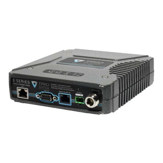
Page 23: Physical Dimensions - Remote Data Radio - Er45E
E Series Ethernet Radio – User Manual Part D – System Planning and Design Physical Dimensions - Remote Data Radio - ER45e Version 08-10 Page 23... -
Page 24: Physical Dimensions - Er45E Mounting Cradle/Din Rail Mount (Optional)
3.5mm Din Rail Din Rail Mount The Din Rail Mount is an optional feature. The Mount is screwed onto the bottom of an ER45e Mounting Cradle giving the unit the ability to be simply ‘clipped’ and Locked onto 3.5mm Din Rail. -
Page 25: Physical Dimensions - Base Station - Eb45E
E Series Ethernet Radio – User Manual Part D – System Planning and Design Physical Dimensions - Base Station - EB45e Version 08-10 Page 25... -
Page 26: Physical Dimensions - Hot Standby Base Station - Eh45E
E Series Ethernet Radio – User Manual Part D – System Planning and Design Physical Dimensions - Hot Standby Base Station - EH45e Page 26... -
Page 27: Part E - Getting Started
Mounting and Environmental Considerations Introduction The ER45e radio comes complete with a mounting cradle and is attached to a panel or tray by means of screws or bolts, using the Welcome to the Quick Start Guide for the ER45e Ethernet hole slots provided. - Page 28 E Series Ethernet Radio – User Manual Part E – Getting Started - ER45e TVIEW+ Adaptor Configuration: Connecting Antennas and RF Feeders The RF antenna system should be installed in accordance with the System Port Description DB9 Female manufacturers notes.
- Page 29 E Series Ethernet Radio – User Manual Part E – Getting Started - ER45e Data Port RS232 Connector Pin outs (DCE) Data Port, Female DB9 The Data Port is wired as a RS232 DCE, configurable for no handshaking (3-wire) interface, or for hardware or software (X-on/ X-off) flow control.
- Page 30 E Series Ethernet Radio – User Manual LAN Ethernet Port Performing a Factory Default The LAN port is a 10/100 Base-T compliant port using an RJ-45 Please read the following notes carefully. Configuration errors connector. These ports support both TIA/EIA-568-A & B wiring as they with Ethernet connections can be difficult to find and resolve.
- Page 31 30VDC. The radio may need to be returned for In most systems, the transmitter by default is controlled service if this occurs. The ER45e remotes have an in Series Diode automatically by the radio when it has data to transmit.
- Page 32 E Series Ethernet Radio – User Manual Part E – Getting Started- ER45e Optimising the Antenna for best RX LED Indicators & Test Outputs signal Radio is Powered Once the unit is operational, it is important to optimise the antenna If all the LEDs are off, no power is reaching the radio modem.
- Page 33 E Series Ethernet Radio – User Manual Part E – Getting Started- ER45e Verifying Operational Health Received Signal Indicator It is possible to verify the operation of the radio modem using the The “RX/SYNC” LED is used to indicate the state of the receiver.
-
Page 34: Eb45E Quick Start Guide
The EB45e is designed for continuous full duplex transmission. Communications Ports An automatic thermostatically controlled fan will operate whenever See ER45e Quick Start Guide Section the internal temperature exceeds 40 degrees Celsius and turn off again when the temperature goes below 35 degrees Celsius. - Page 35 E Series Ethernet Radio – User Manual Part E – Getting Started - EB450 Typical Radio Setup Digital Inputs and Outputs TVIEW+ Diagnostics will recognise an input as being ON when the switch is closed. If the switch is open (or not connected) TVIEW+ The EB45e provides a facility for two channels of digital user inputs diagnostics will recognise the inputs as being OFF.
-
Page 36: Test Mode
LEDs flashing RED at a rate of 1Hz. This indicates internal 15.6Vdc All LED’s GREEN, >=15.7Vdc last LED RED. communications to the exciter has been lost. Contact Trio Support to confirm course of action. The base station may need to be Tx Power: returned to Trio Datacom for repair. -
Page 37: Eh45E Quick Start Guide
E Series Ethernet Radio – User Manual Part E – Getting Started - EH450 EH45e Quick Start Guide Features and Benefits • Individual and identical base stations with separate control Introduction logic changeover panel Welcome to the Quick Start Guide for the EH45e Hot Standby •... - Page 38 E Series Ethernet Radio – User Manual Part E – Getting Started - EH450 Operational Description Ethernet Port redundancy The Hot Standby Controller (HSC) unit is a 1RU rack mounted The Hot Standby set up does NOT have Ethernet redundancy. module that interfaces to two physically separate base stations Any requirements for Ethernet redundancy must be established (each 2RU rack mounted modules) via a number of RF and data...
- Page 39 Base Stations also be used to power the Hot Standby Controller unit. See Figure below for further details. See ER45e Quick Start Guide Section for detailed wiring information. Note: HSC RF Connectors not used on ETSI version...
- Page 40 Part E – Getting Started - EH450 Connecting Antennas and RF Feeders There are 3 primary antenna connection options. All connectors used are standard N Type sockets. See figures below for further details. See ER45e Quick Start Guide for detailed wiring information. Page 40...
-
Page 41: Front Panel Operation
E Series Ethernet Radio – User Manual Part E – Getting Started - EH450 Front Panel Operation Switches Alarm Status LEDs There are 10 alarm LEDs on the front panel, five for base 1 and Select Switch five for base 2. These LEDs provide a general indication of base The 3 position switch (1 / Auto / 2) on the front panel provides the station status. -
Page 42: Part F - Operational Features
: See Part I - TView+ Management Suite If a VSWR of 3:1 or greater is measured, transmitter output power - Programmer for details. is reduced to +31 dBm. (ER45e only) Digital Collision Avoidance System If the “multiple access master” has been configured for full duplex operation, it is possible to use the inbuilt collision avoidance signalling system. -
Page 43: Part G - Commissioning
Part G – Commissioning Antenna Alignment and RSSI Check DC power connector for correct voltage (10-30VDC for ER45e and 11-16VDC for EB45e and EH45e) and polarity, Testing BEFORE plugging in the power connector. Once the RXSIG LED is lit, it is possible to confirm RX signal... -
Page 44: Part H - Maintenance
E Series Ethernet Radio – User Manual Part H – Maintenance Part H - Maintenance Routine Maintenance Considerations The E 45e hardware itself does not require routine maintenance. However all radio products contain crystal frequency references, and the stability of these crystals changes with time. The effect of this is that the product will slowly drift off frequency, and eventually it will require re-calibration. -
Page 45: Part I - Tview+ Management Suite - Programmer
PC serial port (See Appendix C for details) The programmer is used to set configuration parameters within DB9 connector. the ER45e data radio modem and EB45e base station. The utility permits configuration of modems connected directly to the PC as Software well as over the air to a remote unit. -
Page 46: Programmer
Using Windows Explorer open the “Diagnostics” directory on E-Series and selecting ER-45e, or simply connect locally to an the CR-ROM. ER45e unit and select read on the programmer. • Double click on the file called setup.exe To commence programming a unit (radio remote or base station) •... -
Page 47: File Menu
E Series Ethernet Radio – User Manual Part I – TVIEW+ Management Suite - Programmer Pull Down Menus and Toolbar Buttons Exit (also available on the toolbar) This function terminates the program. The user is requested to The items on the pull-down menus can be selected either directly confirm this selection before exiting the application. - Page 48 E Series Ethernet Radio – User Manual Part I – TVIEW+ Management Suite - Programmer desired configuration that can then be written to the unit (remote configuration changes that cause unexpected results resulting in radio or base station). the device reverting to previous configuration if contact is lost. Clone Mode Choose “Make changes and resume contact”...
- Page 49 E Series Ethernet Radio – User Manual Part I – TVIEW+ Management Suite - Programmer Settings Character Layer This menu permits selection of the PC serial port (COM1 to There are two standard formats and a custom format that can be COM16 if available) to be used for communications with the selected by checking the appropriate control button to the left of unit.
- Page 50 E Series Ethernet Radio – User Manual Part I – TVIEW+ Management Suite - Programmer Modbus This selection configures the PAD driver with options • A pre-defined minimum time delay between packets automatically set to implement the MODBUS protocol, e.g. 5 received at the port.
- Page 51 E Series Ethernet Radio – User Manual Part I – TVIEW+ Management Suite - Programmer Handshaking (Packet Modes Only) • Xon/Xoff If the flow control mechanism is XON/XOFF then If the standard PAD is selected (i.e. Any settings apart from the modem uses the standard ASCII control codes SLIP/Diagnostics), then flow control can be either hardware handshaking, XON/XOFF protocol or none.
- Page 52 E Series Ethernet Radio – User Manual Part I – TVIEW+ Management Suite - Programmer Transmitter Mute Adjust The transmitter can be configured for transmit frequency and The currently selected mute level is displayed in the main window power level. below the button in dBm.
- Page 53 E Series Ethernet Radio – User Manual Part I – TVIEW+ Management Suite - Programmer System Parameters Legacy Modulation Schemes: Some modulation types are specifically for backwards compatibility. This includes D Series This section of the main window configures the PTT control, compatibility mode.
- Page 54 Rx codes, a control unit will not “hear” its own transmission, and remotes will not hear the reply from any other remote. For more information please consult the Trio E Series training material available as a power point slide from our website, www.
- Page 55 This mode requires the use of a “SLIP” interface as configured using the packet layer. Trunk Steam mode is normally used in conjunction with Trio Diagnostics software, when connection to a MSR Stream Router or when connecting radios together such as a back-to-back Translate Streams connections as used in multiple point to point links.
- Page 56 E Series Ethernet Radio – User Manual Part I – TVIEW+ Management Suite - Programmer Automatic Diagnostic Reports bit to indicate the channel is now clear to transmit on. The This option allows the configuration of automatic diagnostics. master unit, which is normally a base station, takes about This option automatically appends diagnostics messages when 5ms to detect a transmission from a remote unit and set the user data is transmitted.
- Page 57 Model Type refers to the type of unit. The ER45e is a remote • Hardware indicates whether the radio is half or full duplex. unit and the EE45e is a exciter inside a Ethernet base station •...
- Page 58 E Series Ethernet Radio – User Manual Part I – TVIEW+ Management Suite - Programmer Encryption (option upon purchase) Radio Modes (Ethernet) There are three different Ethernet modes you can configure your radio to be. Access Point - Defines the Access Point in a Network. The function of the access point is to manage bridges and remotes beneath it.
-
Page 59: Status Bar
E Series Ethernet Radio – User Manual Password The Password tab is used to give your units configuration protection. You will notice you have two options: • Disabled - This allows the radios configuration can be read/ written to without a password. •... -
Page 60: Part J - Appendices
2) Disconnect you PC from any other internet/LAN networks. Firmware updates are to be performed on a unit connected locally to Failure to do so may create a conflict in IP addresses or the ER45e the PC. It is recommended that all cabling to the unit be disconnected might not meet the subnet mask specified by you network. - Page 61 “Select TPK File” and a Browse Button. Click on the Browse button and Select the Firmware TPK file you have downloaded from the Trio Datacom Website (www. triodatacom.com) that you wish to upgrade to. Once selected press the “Upload Firmware” button that is to the right of the browse button.
-
Page 62: Installation Instructions
E Series Ethernet Radio – User Manual Part J – Appendices Base Station Display Firmware Update Hot Standby Controller Firmware Update Installation Instructions: Installation Instructions: Update of the front panel firmware uses the firmware update utility supplied with the TView+ Management Suite. Update of the hot standby firmware uses the firmware update utility supplied with the TView+ Management Suite. - Page 63 You must cause the modified files to carry prominent notices stating that you source code in this product on a CD, TRIO Datacom will mail to You a CD with changed the files and the date of any change.
- Page 64 E Series Ethernet Radio – User Manual may not impose any further restrictions on the recipients’ exercise of the rights Schedule 2 granted herein. You are not responsible for enforcing compliance by third parties If this product contains open source software licensed under the OpenSSL to this License.
- Page 65 E Series Ethernet Radio – User Manual list of conditions and the following disclaimer in the documentation and/or other THIS SOFTWARE IS PROVIDED BY THE COPYRIGHT HOLDERS AND materials provided with the distribution. CONTRIBUTORS ``AS IS’’ AND ANY EXPRESS OR IMPLIED WARRANTIES, INCLUDING, BUT NOT LIMITED TO, THE IMPLIED WARRANTIES OF 3.
- Page 66 Radius simultaneously with the application. compliant server Information subject to change without notice. Over-the-air re-configuration of © Copyright 2010 TRIO Datacom Pty Ltd. Modem user parameters. All rights reserved. Issue 08-2010 Data Port: RS232, DCE, Storage of data error and channel...
- Page 67 Hot Standby Controller (HSC) Information subject to change without notice. 5W Version: © Copyright 2009 TRIO Datacom Pty Ltd. Over-the-air re-configuration of all Features: Alarm indications, manual / 2.0 A Nom @ 1 W All rights reserved. Issue 07-2010 parameters.
-
Page 68: Part K - Support Options
When e-mailing questions to our support staff, make sure you tell us the exact model number (and serial number if possible) of the Trio equipment you are working with. Include as much detail as possible about the situation, and any tests that you have done which may help us to better understand the issue.
Need help?
Do you have a question about the ER45E and is the answer not in the manual?
Questions and answers