Table of Contents
Advertisement
Quick Links
WATER-RESISTANT IGNITER TESTER
OPERATION/MAINTENANCE MANUAL
AUSTIN, TEXAS 78737 USA CAGE CODE 1CRL2
PHONE (512) 858-4045 or 1-800-350-5105 (from the USA)
FAX (512) 858-4340 or 1-800-430-5440 (from the USA)
STORAGE AREA
FOR BATTERY CHARGER
MODEL 620A 4R
620A 4R
V
Battery
HI
HI
Charger
VOLTAGE
CURRENT
V
LO
LO
e-mail - info@amptec.com
website http://www.amptec.com
Advertisement
Table of Contents

Related Manuals for Amptec Research 620A 4R


Summary of Contents for Amptec Research 620A 4R
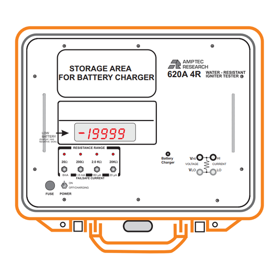
- Page 1 620A 4R FOR BATTERY CHARGER Battery Charger VOLTAGE CURRENT MODEL 620A 4R WATER-RESISTANT IGNITER TESTER OPERATION/MAINTENANCE MANUAL AUSTIN, TEXAS 78737 USA CAGE CODE 1CRL2 PHONE (512) 858-4045 or 1-800-350-5105 (from the USA) e-mail - info@amptec.com FAX (512) 858-4340 or 1-800-430-5440 (from the USA)
- Page 2 AMPTEC RESEARCH will repair or replace the instrument during the warranty period provided it is returned to AMPTEC RESEARCH, freight prepaid. No other warranty is expressed or implied. We are not liable for consequential damages. No liability will be accepted if returned without such permission.
-
Page 3: Table Of Contents
CHAPTER A: RECEIVING AND INITIAL INSPECTION Introduction to the AMPTEC 620A 4R Receiving, Unpacking and Initial Inspection Opening the 620A 4R Ohmmeter and Removal of the Lid AC Adaptor/ Battery Charger- Power Requirements Setup and Use CHAPTER B: 620A 4R FAILSAFE OHMMETER SPECIFICATIONS Table B-2. - Page 4 (Revision D) (620-070 DVM1 and 620N-070 Current (I source) Source Drawing 620-601-2 620A 4R Display Board Assembly Drawing 620-075 620A 4R Cable Drawing - (Test Leads and Battery Charger) Drawing 620-077 620A 4R Relay Board Schematic Drawing 620-078 620A 4R Front Range Switch Schematic...
-
Page 5: Chapter A: Receiving And Initial Inspection
620A Igniter Tester. The 620A 4R has been By calling AMPTEC RESEARCH first, prior made water-resistant and has many features to just returning the 620A 4R, we can often which make it useful in a variety of applications. troubleshoot (based on the symptoms you... - Page 6 C. Air Pressure Equalization (Purge Valve) A-3. Opening the 620A 4R Igniter Tester The 620A 4R has a way to remove it’s lid and removal of the Lid completely, for example when used in an indoor laboratory environment. With the 620A 4R...
-
Page 7: Setup And Use
Battery Charger. order for the connected battery charger to recharge the 620A 4R’s batteries. When the 620A 4R is first turned on, the unit draws more internal power to heat up the unit’s ovenized zener voltage reference. If the “Low A fully charged battery pack typically powers Battery”... - Page 8 Instrument Display . . (20,000 count) 4½ digit Super Bright Light Emitting Diodes (LED) Over-Range Indication ....( select next higher range) 620A 4R Display flashes Measurement Update Rate .
-
Page 9: Chapter C: Replacement, Optional And Accessory Items
The rechargeable NICAD batteries installed in the 620A 4R should provide trouble-free operation. Replacement, however, will eventually be necessary. The 620A 4R uses four 1.2V cells (5.0 AHr recommended) installed in a reusable battery box. The batteries are held in Option 300: 4-Wire Kelvin Lead Set place by a metal retaining plate. -
Page 10: Test Lead Sets
Option "401" is partially a 4-wire lead set (up to the probe tip, 2 and 2 style) terminated with single handheld probe test points. The “401” also has the standard 620A 4R dual banana lead plugs that connect directly to the main 620A 4R measurement panel mount banana jacks (red and white). - Page 11 When the AMPTEC 620A4R is measuring 1.2345 Ohms the Option “620ISO” outputs 123.45 mV DC. The operator can connect any system DVM (i.e HP , Fluke etc,) with a GPIB interface which can be directly connected to a PC for automated measurements.
-
Page 12: Chapter D: Operation, Functional Self-Test And Use
The pushbutton for the (20 Ohm ) lowest resistance range is just below the display on the left, (see item 11 of the 620A 4R See Next Page for a Detailed Front Panel Diagram.). When a given range is 620A-4R Front Panel Diagram selected an indicator LED informs the user. - Page 13 2. Purge Valve provides air pressure leads to prevent mis-connection. equalization to open the 620A 4R case after a transit involving an altitude change if unit will 5. Battery Charger Jack - When the low not easily open.
-
Page 14: Fuseholder
If you know you will be using latch up to open. the 620A 4R again in 10 to 15 minutes, you actually conserve battery power by not turning 11. Resistance Ranges 20ohms, 200ohms, 2.0 it off. -
Page 15: Connections
(they can’t plug in horizontally) . the instrument is in the 2 wire resistance mode. of the 620A 4R. AMPTEC 620A 4R leads have the 4 wire current high, current low as well as All wiring including harness wires from the two... -
Page 16: Failsafe Operation
If this case, please contact regular 4 ½ digit numeric display. The negative your local AMPTEC RESEARCH Service polarity display LED (see item 6 of the 620 Office, or call 1-800-350-5105 or (512) 447-... - Page 17 It is possible for the user to receive a low battery indication on a single range only (particularly the 20 ohm range), while the 620 series igniter tester remains well within operating limits on other ranges. Unless the user observes a continuous low battery indication during measurement, readings are still valid.
-
Page 18: Chapter E General Operation And Design
General eliminated by reviewing Chapters B and D, the following guidelines have been established to The AMPTEC RESEARCH 620A-4R Igniter help solve the problem. Tester is shown in block diagram form in Figure E-1. All diagrams and information disclosed in E-2-1. - Page 19 When soldering, heat the PCB pad and the lead of the component, not the solder. After several seconds of the component lead in contact with the hot soldering iron apply solder smoothly and evenly onto the PCB pad and component lead not the soldering iron.
-
Page 20: Circuit Descriptions
E-4. Analog to Digital Conversion E-3. Circuit Descriptions The A to D conversion is done with a ICL8068 The circuit descriptions which follow are /ICL71C03 chip set. The ICL8068 takes care of referenced to Figures E-1, E-2, E-3 and the the analog part and the ICL71C03 takes care of schematic diagrams at the back of this manual. - Page 21 C INT R INT BUFFER BUFFER INTEGRATOR COMPARATOR 1 µF ZERO CROSSING DETECTOR C REF C AZ C STRAY V IN FIGURE E-2A. PHASE l AUTO-ZERO C INT R INT BUFFER BUFFER INTEGRATOR COMPARATOR 1 µF ZERO CROSSING DETECTOR C REF C AZ C STRAY V IN...
-
Page 22: Ohms-To-Dc Converter
Detailed Description Analog Section E-4-1. Reference Voltage Figures E2 diagrams A thru D shows the The precision reference voltage required to do equivalent circuit of the analog section in 3 the A/D conversion is developed by IC201. The different phases of operation. The system will zener voltage is attenuated to approximately - perform conversions at a rate determined by the 0.5V . -
Page 23: Failsafe Design
E-5-2 Constant Current Circuit Operation igniter could not exceed safe limits, because the -5 volt and +5V supplies includes inherent Assume that terminals I and I of Figure E-3 current limiting. Because of the design of both supply isolation transformers T101 and T102, are shorted, and 1 volt is applied to E so that I the ±5 volt supplies can only deliver 20 to 25 is positive. -
Page 24: E-7 . Ultra-Safe Power Supply Scheme
The 620A Tester measurement circuitry is also E-7 . Ultra-Safe Power Supply Scheme failsafe current limited, even under worst case component failure. A simple startup test The +5 volt power supply is provided directly procedure which also has the 620A Tester by the batteries (for driving the LED displays user perform a functional check using a and digital logic). - Page 25 Figure E-4. LED Display Pin Functions E-8. Relay Board General Operation The internal 620A-4R PCB labeled “620-relay board” replaces the range switch S1 on the main board. IC-1 is actually a ribbon cable header that goes to the top panel and connects to the range push buttons (covered by silicone rubber boots) and their corresponding panel mount LEDS.
-
Page 26: General
This section of the manual contains routine Following standard resistors are required to maintenance information regarding the calibrate the 620A-4R Igniter Tester . AMPTEC RESEARCH Model 620A series Precision Resistors: igniter tester. Calibration should be performed 0.1 ohm ± 0.01% Accuracy on a regular basis to ensure continued 10 ohm ±... -
Page 27: Battery Replacement Instructions
4) Secure the new batteries in place by re- 2. Adjust RV1 for a display indication of placing the tie wraps. 100.00. 5) Replace the 620A-4R Igniter Tester front 3. Check the 2.0 KOhm range with the 1000 panel top plate and re-tighten the calibration Ohm Standard Resistor. - Page 31 CHAPTER H SCHEMATICS AND ASSEMBLY DIAGRAMS The following schematic diagrams have been included in this manual: 620-600 1 page 620 Main Board Assembly (Rev D) 620-601-2 1 page 620 Display Board Assembly 620-070 3 pages 620 Ohmmeter Schematics 1) DVM1 (Rev D) 2) I_SRC (Current Source - Rev D) 3) DISP (Display - Rev D) 620-077...
- Page 34 FUSE CHARG MAIN C111 D101 Q102 C101 IC11 T101 IC10 Q101 D102 C113 C112 Q104 D103 C102 T102 VLO VHI D104 Q103 R205 R204 JUMPER R207 R206 R209 R202 C201 R213 R222 R221 Q202 R220 C202 D203A,B R218 Q4 Q3 Q2 Q1 R217 R227A D202...
Need help?
Do you have a question about the 620A 4R and is the answer not in the manual?
Questions and answers