Table of Contents

Related Manuals for Telebit NetBlazer STi

Summary of Contents for Telebit NetBlazer STi
- Page 1 Book Page 1 Thursday, March 27, 1997 10:55 AM NetBlazer ® STi and 40i Installation Guide ¤ ¤ Net Bla zer STi Ne tB laz er 40 RESE T POWE R RESE T POW ER Part Number 90453-02 Revision A0 Copyright © 1997 Telebit, Inc. Printed in U.S.A.
- Page 2 Book Page 2 Thursday, March 27, 1997 10:55 AM...
- Page 3 Software. You may make one (1) copy of any Software licensed from Telebit solely for back up or archival purposes, provided you reproduce and include Telebit's copyright and other proprietary rights notices on and in any such copy.
- Page 4 Software is recorded will be free from defects in materials and workmanship under normal use for a period of ninety (90) days from the date of delivery. Telebit's entire liability and your exclusive remedy pursuant to this limited warranty shall be limited to replacement of the defective media.
- Page 5 Telebit, Inc. has prepared this document solely for use by Seller’s personnel, customers, and licensees. The information contained in it is the property of Telebit, Inc. and shall not be copied, photocopied, translated, or reproduced in any electronic or machine readable form, either in whole or in part, without the written approval of Telebit, Inc..
-
Page 6: Power Cord
Telebit, Inc. and Seller will in no event be held liable for direct, indirect, or incidental damages resulting from any defect or omission in this manual, or any other related items and processes, including, but not limited to, any interruption of services, loss of business or anticipatory profits, or other consequential damages. - Page 7 All additional boards having a direct connection to the public network must have the mandatory approvals. With the NetBlazer STi and 40i, indirect connections to the Wide Area Network (WAN) are established with synchronous, asynchronous, or ISDN plug-in boards. These devices must comply with the requirements of the country in which they are used.
- Page 8 Book Page viii Thursday, March 27, 1997 10:55 AM To maintain the independent approval of the X.21 board, it is essential that, when other option boards are introduced that use or generate a hazardous voltage, the minimum creepages and clearances specified in the table below are maintained. A hazardous voltage is one that exceeds 42.4V peak a.c.
-
Page 9: How To Use This Manual
Book Page ix Thursday, March 27, 1997 10:55 AM How to Use This Manual This manual is a guide to installing NetBlazer STi and NetBlazer 40i hardware. It is intended to be used by network administrators and/or service personnel responsible for hardware installation. -
Page 10: Related Documentation
Book Page x Thursday, March 27, 1997 10:55 AM Related Documentation Telebit recommends that you configure your NetBlazer using the NetBlazer Setup Utility. For instructions, see the NetBlazer Setup Utility Guide that was shipped with your NetBlazer. The NetBlazer Configuration Guide describes how to use NetBlazer commands to customize a broad range of operational parameters. -
Page 11: Table Of Contents
General Planning......................1-9 2 NetBlazer Installation ..................3-1 AC Power Cord Connection .................... 3-1 Installing a NetBlazer STi Option Board................. 3-1 Closing the NetBlazer STi Case ..................3-2 Installing a NetBlazer 40i Option Board ................. 3-2 Closing the NetBlazer 40i Case ..................3-4 Optional Rackmount Kit .................... - Page 12 Book Page xii Thursday, March 27, 1997 10:55 AM C Telebit Cables ....................C-1 RS-232 Cables ......................C-2 Null-Modem Adapter....................C-3 Gender Adapter......................C-4 RS-449 Cable for the SYN449 Board................C-5 RS-232 Cable for the SYN232 Board................C-6 V.35 Cable for the SYN35 Board ................C-7 RS-530 Cable for the SYN530 Board................C-8...
-
Page 13: Introduction
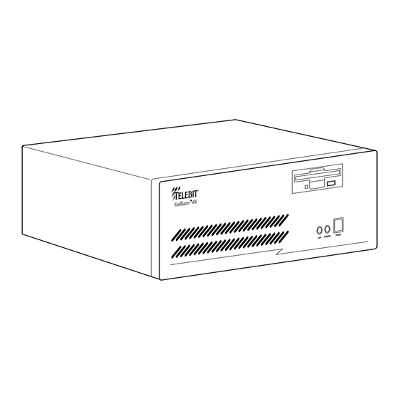
Integrated Services Digital Network (ISDN) and Switched 56. When used with a NetBlazer MTA32 Rack Adapter, the NetBlazer STi can also act as a remote-access communications server for telecommuting applications that require up to 32 serial ports for modems. - Page 14 POW ER Figure 1-1. The NetBlazer STi Figure 1-2 shows the NetBlazer STi front panel with a 1.44-Mbyte, 3.5-inch floppy diskette drive, two status indicators, and a reset switch, all located on the right side. The LED labeled LAN shows Ethernet network activity. The LED labeled POWER shows that power is on.
-
Page 15: Netblazer 40I Description
Book Page 3 Thursday, March 27, 1997 10:55 AM Figure 1-3 shows a typical NetBlazer STi rear panel. The chassis I/O ports, line00 and line01, are RS-232 9-pin ports available for connection to a modem or asynchronous terminal at speeds up to 115.2 Kbps. The console port is also an RS-232 serial port for use with an asynchronous terminal op- erating at 9600 baud. - Page 16 Book Page 4 Thursday, March 27, 1997 10:55 AM ¤ N et B la ze r 4 0 RE SE T PO WE R LA N Figure 1-4. The NetBlazer 40i Figure 1-5 shows the NetBlazer 40i front panel with a 1.44-Mbyte, 3.5-inch floppy diskette drive, two status indicators, and a reset switch, all located on the right side.
-
Page 17: Hardware Configuration
Blazer 40i includes12 megabytes of system memory. Hardware Configuration You can install up to three option boards in the NetBlazer STi, and up to six option boards in the NetBlazer 40i. Table 1-1 provides a list of available options. Contact your distributor or reseller for up-to-date ordering information on NetBlazer options. - Page 18 Async Multiport Board Multiport controller with 8-port expansion cable. ASYN8 Async Multiport Board and one The NetBlazer STi/40i supports up to four ASYN8 8-port multiple terminal adapter controller boards with up to eight MTAs evenly dis- (MTA) tributed among the ASYN8 controller boards for a total of 64 RS-232 ports.
-
Page 19: Modem Compatibility
Modem Compatibility The NetBlazer currently supports the Telebit modems and firmware levels listed in Table 1-2. If you have a Telebit modem that is not at the required firmware level, contact Telebit Customer Support at 508.656.9453 for infor- mation about obtaining a firmware upgrade. - Page 20 Book Page 8 Thursday, March 27, 1997 10:55 AM Table 1-2. Supported Telebit Modems Firmware Level for Modem Firmware Level AppleTalk ARA Service Granite Module 1.00 or later 2.00 or later FastBlazer 88x0 Series 1.00 or later 2.00 or later TeleBlazer V1.100b-V34_DS Z201 or later...
-
Page 21: Preinstallation Planning
Book Page 9 Thursday, March 27, 1997 10:55 AM Preinstallation Planning Choosing a Location When choosing a location for the NetBlazer, make certain that you have the appropriate number of AC outlets, cables, telephone lines, and LAN con- nections for the NetBlazer and its externally connected devices (e.g., mo- dems and terminal adapters). - Page 22 Book Page 10 Thursday, March 27, 1997 10:55 AM 1-10 Introduction 90453-02 Rev A0...
-
Page 23: Netblazer Installation
Additionally, a list of LAN and WAN connection types sup- ported by the NetBlazer STi and 40i is provided. After you have installed your NetBlazer STi or 40i, you can configure its software. This procedure, which involves setting up the IP, IPX, or AppleTalk addresses, routes, and users for the NetBlazer, is described in the NetBlazer Configuration Guide and the NetBlazer Setup Utility Guide. -
Page 24: Closing The Netblazer Sti Case
Figure 2-1. NetBlazer STi Option Board Installation Closing the NetBlazer STi Case Lower the top cover onto the NetBlazer STi so that the notches in the guide rails on the inside of the top cover align with the side edges of the front panel. - Page 25 Book Page 3 Thursday, March 27, 1997 10:55 AM Choose an unused option slot and remove the filler panel from the back panel. As shown in Figure 2-2, carefully guide the option board into its slot so that the board’s edge connector is aligned with the slot connector and the cable connectors extend through the slot opening.
-
Page 26: Closing The Netblazer 40I Case
Slide the top cover back into position and replace the three cover mounting screws on the back of the case. Optional Rackmount Kit For rackmounted systems, Telebit offers an optional rackmount kit for both the NetBlazer STi (model number NBRK-STI) and NetBlazer 40i (model number NBRK-40i). -
Page 27: Using The Reset Button
Book Page 5 Thursday, March 27, 1997 10:55 AM Using the Reset Button With the NetBlazer’s power on and a diskette in the floppy diskette drive, you can reset the NetBlazer by pressing the reset button on the front panel instead of using the power switch on the back panel. - Page 28 Book Page 6 Thursday, March 27, 1997 10:55 AM NetBlazer Installation 90453-02 Rev A0...
-
Page 29: A Specifications
Book Page 1 Thursday, March 27, 1997 10:55 AM Specifications Specifications for the NetBlazer STi are listed in Table A-1: Table A-1. NetBlazer STi Specifications Item NetBlazer STi Dimensions: Height 4.3 inches (107millimeters) Width 16.3 inches (414 mm) Depth 15.5 inches (394 mm) Weight 19 pounds (8.6 kilograms) without option boards... - Page 30 Book Page 2 Thursday, March 27, 1997 10:55 AM Specifications for the NetBlazer 40i are listed in Table A-1: Table A-2. NetBlazer 40i Specifications Item NetBlazer 40i Dimensions: Height 6.75 inches (172 mm) Width 16.8 inches (427 mm) Depth 16.25 inches (413 mm) Weight 23 pounds (10.4 kilograms) without option boards Environmental:...
-
Page 31: B Cable Applications
The following diagrams show recommended cabling for NetBlazer connec- tions for those who want to build their own cables for specific applications. Select the length and the connector gender for your application. Telebit sells a variety of cables for different applications; contact your distributor. See Appendix C for Telebit cables. -
Page 32: Standard Asynchronous Rs-232 Cables
Book Page 2 Thursday, March 27, 1997 10:55 AM Standard Asynchronous RS-232 Cables NetBlazer (DB-9) Modem (DB-25) Signal Ground Transmitted Data (TD) Received Data (RD) Request to Send (RTS) Clear to Send (CTS) Data Set Ready (DSR) Data Carrier Detected (DCD) Data Terminal Ready (DTR) Ring Indicator (RI) DB-9 to DB-25 RS-232 Cable... -
Page 33: Null-Modem Asynchronous Rs-232 Cables
Book Page 3 Thursday, March 27, 1997 10:55 AM Null-Modem Asynchronous RS-232 Cables NetBlazer (DB-9) Terminal (DB-25) Signal Ground DB-9 to DB-25 RS-232 Null-Modem Cable NetBlazer (DB-25) Terminal (DB-25) Signal Ground DB-25 to DB-25 RS-232 Null-Modem Cable Figure B-2. RS-232 Null-Modem Cables 90453-02 Rev A0 Cable Applications... -
Page 34: Dual Bri Isdn Board Cable
To use the RS-232 interface to the DSU/CSU, you need a straight-through RS-232 cable with a male DB-25 connector on each end of the cable. Wiring for this cable is shown in Figure B-4. Telebit offers p/n 14358-01, which supports these signals, and p/n 14158-01, which supports all 25 wires. - Page 35 To use the RS-422/RS-449 interface to the DSU/CSU, you need a special cable with a male DB-25 connector for the NetBlazer and a male DB-37 connector for the DSU/CSU. Configure the cable as shown in Figure B-5. This cable is available from Telebit as p/n 14385-01. 90453-02 Rev A0 Cable Applications...
- Page 36 Book Page 6 Thursday, March 27, 1997 10:55 AM DB-25 DB-37 Shield Send Data SDA Send Data SDB Receive Data RDA Receive Data RDB Request to Send RSA Request to Send RSB Clear to Send CSA Clear to Send CSB Data Mode DMA Data Mode DMB Terminal Ready TRA...
-
Page 37: C Telebit Cables
Book Page 1 Thursday, March 27, 1997 10:55 AM Telebit Cables This appendix shows the wiring diagrams for the following Telebit cables and adapters. The following four items you received with your NetBlazer: RS-232 cable (DB-25 male to DB-25 female, p/n 12732-01) •... -
Page 38: Rs-232 Cables
Book Page 2 Thursday, March 27, 1997 10:55 AM RS-232 Cables DB-25F DB-25M Figure C-1. RS-232 Cable, DB-25 to DB-25, p/n 12732-01 Telebit Cables 90453-02 Rev A0... -
Page 39: Null-Modem Adapter
Data Carrier Detected (DCD) Data Terminal Ready (DTR) Ring Indicator (RI) Figure C-2. RS-232 Cable, DB-25 to DB-9, p/n 14339-01 Null-Modem Adapter DB-25M DB-25F Chassis Ground Signal Ground Figure C-3. Null Modem, DB-25 to DB-25, p/n 14168-01 90453-02 Rev A0 Telebit Cables... -
Page 40: Gender Adapter
Book Page 4 Thursday, March 27, 1997 10:55 AM Gender Adapter DB-25F DB-25F Figure C-4. Gender Adapter, DB-25 to DB-25, p/n 14338-01 Telebit Cables 90453-02 Rev A0... -
Page 41: Rs-449 Cable For The Syn449 Board
CTSA CTS- DSRA DSR- DCD- DCDA DCD+ DCDB CTS+ CTSB TXD+ TXDB RXD+ RXDB RTS+ RTSB DTR- DTRA DSR+ DSRB DTR+ DTRB Figure C-5. RS-449 Cable, DB-26 to DB-37, p/n 12720-01, for the SYN449 Board 90453-02 Rev A0 Telebit Cables... -
Page 42: Rs-232 Cable For The Syn232 Board
Book Page 6 Thursday, March 27, 1997 10:55 AM RS-232 Cable for the SYN232 Board DB-26M DB-25M Figure C-6. RS-232 Cable, DB-26 to DB-25, p/n 12721-01, for the SYN232 Board Telebit Cables 90453-02 Rev A0... -
Page 43: V.35 Cable For The Syn35 Board
Book Page 7 Thursday, March 27, 1997 10:55 AM V.35 Cable for the SYN35 Board DB-26M V.35M TCLK+ TCLK- RCLK+ RCLK- Figure C-7. V.35 Cable, DB-26 to DB-25, p/n 12722-01, for the SYN35 Board 90453-02 Rev A0 Telebit Cables... -
Page 44: Rs-530 Cable For The Syn530 Board
RTS- RTSA CTS- CTSA DSR- DSRA DCD- DCDA DCD+ DCDB CTS+ CTSB TXD+ TXDB RTS+ RTSB DTR- DTRA DSR+ DSRB DTR+ DTRB Figure C-8. RS-530 Cable, DB-26 to DB-25, p/n 13203-01, for the SYN530 Board Telebit Cables 90453-02 Rev A0... -
Page 45: X.21 Cable For The Synx21 Board
B (A) SIGNAL GND TXD+ T (B) RTS+ C (B) RXD+ R (B) CTS+ I (B) RXC+ S (B) TXC+ B (B) Figure C-9. X.21 Cable, DB-26 to DB-15, p/n 14257-01, for the SYNX21 Board 90453-02 Rev A0 Telebit Cables... -
Page 46: Ns1 Single-Port Synchronous Board Cable
NS1 Single-Port Synchronous Board Cable The NS1 synchronous board is shipped from the factory configured for a DSU/CSU with a V.35 interface. Telebit provides the cable used to connect the NetBlazer to a DSU/CSU using a V.35 interface. The wiring diagram for the V.35 cable, p/n 12079-01, is shown in Figure C-10. - Page 47 Note: Although any of the features can be disabled by placing a jumper on the pins, Telebit recommends NOT changing the settings for these features from their factory defaults. Change a setting ONLY following explicit instructions from Telebit Customer Support.
- Page 48 Book Page 2 Thursday, March 27, 1997 10:55 AM line00 line01 line02 E1 & E3 - EN0 ACTIVE COM1 COM2 COM3 E2 & E3 - EN0 DISABLE 16552 DISABLE IRQ10 ENABLE COMBO IO DISABLE WATCHDOG DISABLE Figure D-1. NetBlazer Combo Board The status LEDs on the combo board have the following functions: •...
Need help?
Do you have a question about the NetBlazer STi and is the answer not in the manual?
Questions and answers