Table of Contents
Advertisement
Distributed by: minilablaser.com
• QSS-3201 Digital
• QSS-3201SM Digital
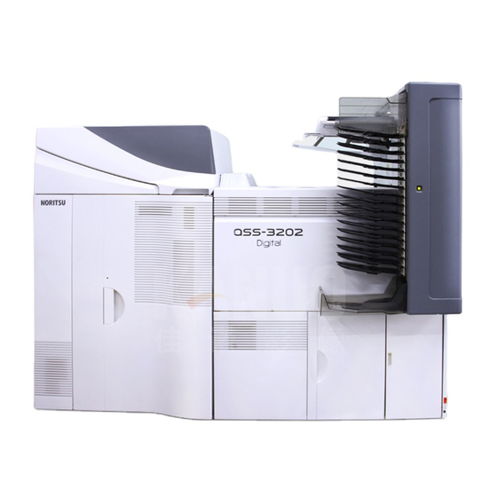
• QSS-3202 Digital
• QSS-3202SM Digital
• QSS-3203 Digital
• QSS-3203SM Digital
• QSS-3211 Digital
• QSS-3211SM Digital
• QSS-3212 Digital
• QSS-3212SM Digital
• QSS-3213 Digital
• QSS-3213SM Digital
• Do not allow any people other than the service personnel to work. It may cause them electric shock, burn and injury.
Noritsu Quick Service System
QSS-32 series
Installation Manual
This manual is for the following machines.
[for service personnel only]
• QSS-3202 PRO Digital Printer
• QSS-3202SM PRO Digital Printer
• QSS-3203 PRO Digital Printer
• QSS-3203SM PRO Digital Printer
Advertisement
Table of Contents


Need help?
Do you have a question about the QSS-3201 and is the answer not in the manual?
Questions and answers