Table of Contents
Advertisement
Advertisement
Table of Contents

Related Manuals for Bentel J424

Summary of Contents for Bentel J424
- Page 1 CONVENTIONAL F I R E P A N E L S INSTALLATION MANUAL ®...
- Page 2 The J424 and J408 Control panels comply with the essential requirements of standards EN54-2; EN54-4. The J424 and J408 Control panels, all their accessories and functions, except those listed below and unless otherwise specified (see notes marked A), are IMQ Security Systems Grade II Listed.
-
Page 3: Table Of Contents
INSTALLING THE CONTROL PANEL The J424 and J408 Control panels Installing accessory boards Accessory Items Installing Extinguishment Modules Description Installing Expander Module Kit (for J424 ONLY) 22 Inputs Display Module (for J424 and J400-REP ONLY) 24 Outputs Installing Repeaters Operating features... - Page 4 PROGRAMMING FROM A PC PROGRAMMING FROM THE PANEL Enrolling: Expander Modules Accessing the Programming session Enrolling: Extinguishment Modules Exiting the Programming Session Activation Mode The “ZONES” Programming Phase Times The “TIMES” Programming Phase Zones The “OUTPUTS” Programming Phase Manual Extinguishment Input The “PANEL”...
-
Page 5: Introduction
3k5 of IEC 721-3-3:1978. The J400-EXT Extinguishment Module IS NOT an IMQ-SECURITY SYSTEMS listed product. The J424 and J408 Control panels provides the follo - wing features: 8 Supervised/Bypassable input zones J400-LCD Display Module (the J408-2 provides 2 and the J408-4provides 4);... -
Page 6: Outputs
Ø Negative pull-down to 0 V on the R terminal of the lure to the Control panel. zone that generated the Alarm; Ø Negative pull-down to 0 V on the OC terminal, that is, if it is programmed to signal Alarm status. Conventional Fire Panels J424/J408... -
Page 7: Interface
Ø TROUBLE Ø slow blinking on the LED concerned. Silence status will be signalled by: Display The J424 Control panel can house the Ø an audible signal (lasting 1 second) followed by a J400-LCD Module. This module provides written infor - long pause (lasting 5 seconds);... -
Page 8: Extinguishment Module
PCB. Z24) and the Test key simultaneously. n Power Supply n Extinguishment Module The power supply system of the J424 and J408 Control This section describes how the J400-EXT Extingui - panels complies with EN54-4. shment Module operates. -
Page 9: Identification Of Parts
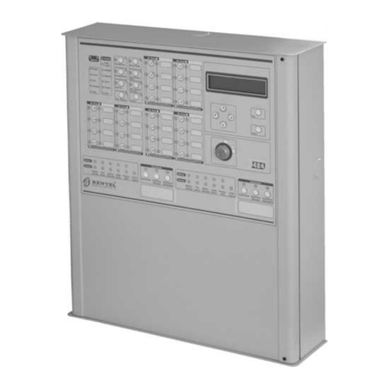
IDENTIFICATION OF PARTS The Status LEDs Some LEDs indicate more than one status, howe - ver, in most cases the LEDs signal as follow: The following section describes how the Control panel ON (glowing) indicates DISABLED status; LEDs operate, and the actions that can be taken during Fast blinking indicates a FAULT condition;... - Page 10 Logic Extinguish. Manual Automatic Extinguish. valve Ext. Ext. Ext. Switch Unit Extinguish. valve Ext. Ext. Ext. Switch Unit Extinguish. Extinguish ® Figure 1 Front view of the J424 Control panel J424 (a), J408 Control panel (b) and J400-REP Repeater (c)
- Page 11 Zone Alarm Zone Alarm Fault Alarm Logic Silence Night Mode Unit Pre-al. 24V/24R Ack./Evac. Disab./Fault Test Battery Disab. Ground Reset Disab./Fault Telecom Periph. Telecom Mains Mains Disab. Buzzer Test Disabled/Fault/Test Disabled/Fault/Test Disable Fault Electro- Manual Disab. Pres. Logic Extinguish. Manual Automatic valve Ext.
- Page 12 Figure 2 Maximum configuration of the J424 Control panel...
- Page 13 B016 B– 11 12 13 14 15 17 18 20 21 22 23 24 IDENTIFICATION OF PARTS...
- Page 14 Description of Parts Description Surface Cable conduit entry This section describes the components of the J424 and Zone label slots J408 Control panels, and J400-REP Repeater. Display Door screws Unless otherwise stated, the numbers in boldface in this Keyswitch (Access Level 2)
- Page 15 Flat cable (accessory item): for the Display Batteries (NOT supplied!): Module connection J408 = two 7 Ah @ 12 V Extinguishment Module no.2 (accessory J424 = two 17 Ah @ 12 V item) Expander no. 1 (accessory item) Wire run Bag containing keys, resistors and diodes Flat cable (accessory item): for the Expander Module no.
- Page 16 Description Anchor screw location holes Chased cable conduit entry RS485 Interface Soldered Earthing screw Figure 4 Maximum configuration of the J400-REP Repeater: a) backplate; b) frontplate (inside view) Conventional Fire Panels J424/J408...
- Page 17 IDENTIFICATION OF PARTS...
- Page 18 Mains power terminals (230 V / 50 Hz) Switching-power-supply screws Switching-power-supply fuse — protects aga - inst overload: J408 = F 2A 250V J424 = F 3.15A 250V Jack for Extinguishment Module nr. 2 or the Display Module Microprocessor Jack for the Main board or Display Module Reserved Jumper —...
- Page 19 Expander Module and the preceding pe - ripheral device or Main Board Expander Control Board jack B– Figure 6 Identification of Parts: a) Expander Module; b) Expander Control Board; c) Display Module; d) RS485 Repeater Interface; e) J424 Control panel Switching-po - wer-supply IDENTIFICATION OF PARTS...
-
Page 20: Description Of The Control Keys
Fault Electro- Glowing indicates “Extinguishment” in course Fast blinking indicates power supply failure to valve the electrovalve connected to output EV, or that the latter is either open or shorted Glowing indicates “Pre-Extinguishment” in cour - Fast blinking indicates that terminals [+] and [–] Ext. -
Page 21: Installing The Control Panel
Figure 7 J408: Installing the Extinguishment Module observed. 90 91 J424 The J424 Control panel can house 2 Extingui- shment Modules (28 and 31 in the Figure on page 12). Install the Extinguishment Module, as follows. 1. Remove the screws (4) and open the Control panel. -
Page 22: Installing Expander Module Kit (For J424 Only)
Installing Expander Module Kit (for J424 ONLY) Figure 9 Connecting ONE Extinguishment Module (a) This Expander Module Kit comprises an 8 zone Expan - or TWO Extinguishment Modules (b) to a J424 Control der Module and the Expander Control board. The panel: 9) Main Control Board;... - Page 23 Expander Module Install Expander Modules as follows. Expanders Modules must be installed befo- re mounting the Control panel to the wall. 1. Remove the screws (4) and open the Con- trol panel. 2. Insert the reverse locking supports (93) into their respective locations (94) (as per Fig.
-
Page 24: Display Module (For J424 And J400-Rep Only)
The J424 Control panel and the J400-REP Repeater both accept Display Modules (see 6 pages 12 and 16). This instructions in the following section refer to the connection of an LCD Module to a J424 Control pa- nel, the connection procedure for the J400-REP Repeater is similar. -
Page 25: Installing Repeaters
Installing Repeaters Installing the Control panel Work carefully through the following steps (see the Fi - The Display Module (if used) must be installed be- gures on pages 10, 12 and 14). fore the Repeaters. 1. Remove the screws (4) and open the Control panel. Repeaters can be wall mounted, or flush mounted to an ®... -
Page 26: Main Board Terminals
If Alarm conditions are present when the Silence Time expires, the Repeat Output will re-activate. Up to 0.1 A can circulate on each Repeat Output. Outputs R1, R2, ..., R8 accept devices that operate within SELV limits ONLY. Conventional Fire Panels J424/J408... - Page 27 [DL] Supervised/Bypassable Dialler Output The ALARM Output accepts devices that operate This Output is for Dialler activation. within SELV limits ONLY. Operating principles This Normally-Open Output (open-collector) will: TROUBLE Silenceable Trouble Output Ø pull down to 0 V (negative) when the Alarm Signal - This Output is for Trouble signalling.
-
Page 28: Extinguishment Module Terminals
Activation of the IE Input will be indicated by Glowing on will be indicated by fast blinking on the Fault Pre Ext. LED. the ON Disab. Ext. LED. Up to 1 A can circulate on the PR Output. Conventional Fire Panels J424/J408... - Page 29 CONVENTIONAL F I R E P A N E L S USER’S INSTRUCTIONS ®...
- Page 30 Ø the Zone Alarm LEDs of the zones concerned (On); Ø a fast intermittent audible signal (0.2 second beep followed by a 0.2 second pause); Ø a “ALARM” message, similar to the following: ALARM ON ZONE 01 Warehouse Conventional Fire Panels J424/J408...
-
Page 31: Pre-Extinguishment Phase
STAT. DISPLAY DESCRIPTION CONSEQUENCE FAULT ON ZONE 01 Disabled A detector is missing from The detectors downstream of Fast Warehouse /Fault zone no. 1, or zone no. 1 is the missing detector will be blink. /Test shorted or open unable to signal fire conditions Logic Unit The Control panel is blocked The Control panel will be una -... - Page 32 Module for fire extinguishment purposes (up to 2 Extin- Ack./Evac. button AT LEAST 5 seconds. guishment Modules can be connected to J424 Control panels). These devices have been specially designed To activate an Alarm when the Control panel is in...
-
Page 33: Disable Extinguish. Button
n Pre-extinguishment Phase n Manual Extinguishment If the programmed extinguishment conditions occur The Extinguishment Module can be activated from ma - (programmed by your Installer), the Extinguishment nual call-points (ask your Installer for details). Module will generate the Pre-extinguishment phase which will be signalled by: Manual activation of the Extinguishment Module is si - Ø... - Page 34 The device concerned has been restored Table 2 Event Descriptions (Continues ...): AV = Extinguishment Done; EM = Manual Extinguishment; EV = Electro - valve; IE = Inhibit Extinguishment ; PR = Pre-extinguishment; PS = Pressure switch. Conventional Fire Panels J424/J408...
- Page 35 EVENTS DETAILS DESCRIPTION PS ACTIVATED Extinguishment Mod. nr. PS Input of Extinguishment Mod. nr. is operating PS INPUT FAULT Extinguishment Mod. nr. PS Input of Extinguishment Mod. nr. shorted or open PS INPUT RESTORE Extinguishment Mod. nr. PS Input of Extinguish. Mod. nr. executed RESET None Reset executed...
- Page 36 . Silenced devices will be re-enabled auto- matically in the event of a new ALARM. The Silence button can be used during Access Le - vel 2 only. Ack./Evac. ON (glowing) indicates that the program - med Investigation time is running. Conventional Fire Panels J424/J408...
-
Page 37: The System Wiring
AE Activated Extinguishment Output Connect Conventional Fire Detectors as per Figure 14. This Output is for “Activated Extinguishment” signal. Operating principles Operating principles Ø Terminals L1 and L2, respectively, the power input Ø Standby status: negative pull-down to 0 V on the [+] and output terminals of the detector (these terminals terminal;... -
Page 38: Connecting Call-Points
Figure 15 Wiring diagram of 3 detectors with Normally-Open Outputs and a Call point with zero ohm contact resistan - ce: 109) 3900 ohm, 1/4 W EOL resistor (orange-white-red-gold); 111) 680 ohm resistor; 112) 680 ohm resistor (necessary when Call-point priority option is DISABLED) or 270 ohm resistor when Call-point Priority option is ENABLED). Conventional Fire Panels J424/J408... -
Page 39: Connecting Signalling Devices
4 - 20 mA Gas detectors 4 - 20 mA Gas detectors n Connecting Signalling Devices can be connected to terminals [Z1] ONLY on the Main NAC1, NAC2 and ALARM outputs are for the alarm si - Board and Expander Module, as per Figure 16b. gnalling device connections. -
Page 40: Connecting A Repeater
Fire bell Fire bell – – Warning lamp Warning lamp FIRE FIRE ALARM ALARM – – Figure 18 Wiring diagram of Signalling devices: 109) 3900 ohm, 1/4 W EOL Resistor (orange-white-red-gold); 114) 1N4007 Diode or similar Conventional Fire Panels J424/J408... -
Page 41: Connecting Extinguishment Modules
n Connecting Extinguishment Modules The J400-EXT Extinguishment Mo- 680 W 680 W Manual dule IS NOT an IMQ-SECURITY Extinguishment SYSTEMS listed product. Control Buttons The wiring diagram in Figure 19 shows an Extinguishment Module connected to the Control panel. The EM inputs (Manual Extingui- shment) and IE inputs (Inhibit Extin- guishment) accept Normally-Open 680 W... -
Page 42: Connecting A Power Supply
60 and jumper connectors. The Control panel will monitor the batteries at all times, (refer to Static Test and Dynamic Test). J424: Use 17 Ah @ 12 V YUASA NP 17-12 FR bat- teries; Static Test The Static Test monitors the battery char- J408: Use 7Ah @ 12 V YUASA NP7-12 FR batte- ge during Mains failure. -
Page 43: Thermal Probe
Maintenance DO NOT allow the power cable to cross over ot - her wiring (see Figure 21a). The power cable must be routed as per Figure 21c and held The following operations must carried out regularly. firmly in place by a cable tie (see Figure 21b). A Using a damp cloth (DO NOT USE SOLVENTS OF ANY KIND), remove dust from the Control panel case. - Page 44 Output Voltage of the Switching Power Supply to the indicated value. For example, if the Probe tempe - rature is 22 °C, the Output Voltage of the Switching Power Supply must be set at 27.4 V. Conventional Fire Panels J424/J408...
-
Page 45: Programming From A Pc
PROGRAMMING FROM A PC Enrolling: Extinguishment Modules You can program this system from the Control panel or from a computer, using the J400 application. The Extinguishment Modules page will allow you to This section describes how to program the system from enrol and set up Extinguishment Modules, as follows. -
Page 46: Activation Mode
Disable Extinguishment Input ([IE] terminals). Normally Closed If this option is DISABLED (at Defa - ult), there must be a 3900 ohm resistance across the [+] and [–] terminals of the IE input during Standby status. Conventional Fire Panels J424/J408... -
Page 47: Zones
Zones Standby/Auto.Alarm If the Call point Priority option has been ENABLED, the Control panel will consider the The Zones page will allow you to program the Zones Zone ALARM status when the voltage on its terminals ranges between the value programmed in this field and The chart on the left-hand side of the page shows the the value programmed in the Auto.Alarm/Manual number of zones available on the system, depending... -
Page 48: Options
It will be applied when the Ack/Evac. key is pressed for less than 5 seconds at Access Level 2 (Keyswitch ENABLED or PIN Code entered). Accepted values: 0 to 300 seconds (5 minutes), in steps of 10 seconds Default value: 60 seconds. Conventional Fire Panels J424/J408... -
Page 49: Oc Output Events
n OC Output Events n DL Output This section will allow you to assign one or more of the The Dialler Output ([DL] terminal) will activate when its following events to the OC Output ([OC] terminal), as programmed delay expires. The delay countdown will follows. -
Page 50: Reset
Accepted values: 0 through 5 seconds, in steps of 1 se - cond. Default setting: 2 seconds. n User Code The 4-digit User Code will allow access to Level 2 of the Control panel. Default setting: 1234 Figure 26 The Settings page Conventional Fire Panels J424/J408... -
Page 51: Downloading
Downloading 6. To download a specific page: click the DWLoad button on the page in question. Once the operating parameters have been set up, they To Download several pages: must be downloaded to the respective Control Panel, – select the required page from the Pages menu, as follows. - Page 52 Conventional Fire Panels J424/J408...
-
Page 53: Programming From The Panel
Zone keys (Z1 through Z 8 for the J408; Z1 through Z 24 for the J424). The Program- ming Overlay covers the keys of Zones 1 through 8 Exiting the Programming Session (Z1 . -
Page 54: The "Zones" Programming Phase
Ž ‘ Re p . 4 Decrease time Expander 2 LCD 4 Power 4 ‘ 1 sec ‘ Decrease time ‘ Zone 4 ‘ Zone 8 Figure 30 The “Times” Programming Phase Conventional Fire Panels J424/J408... -
Page 55: The "Outputs" Programming Phase
Œ- Œ- Œ Zone 1 Œ Zone 5 ‘ 640 sec Pre-alarm time Refresh time Zone 1 Zone 5 ‘ ŽAlarm ŽPre-alarm ŽFault ‘ 128 sec Œ Alarm verific. ‘ 320 sec MODULES ... -
Page 56: The "Panel" Programming Phase
‘ ZONES NAC1 Pre-alarm Ž ‘ Re p . 4 Decrease time Expander 2 LCD 4 Power 4 ‘ 1 sec ‘ Decrease time ‘ Zone 4 ‘ Zone 8 Figure 33 The “VARIOUS” Programming Phase Conventional Fire Panels J424/J408... -
Page 57: The "Modules" Programming Phase
n Stabilization Time (Key/LED 1) n Configuration 2 (Key/LED 7) The LED will go On to indicate that the system is ready The LED will go On to indicate that the system is ready to start the programming procedure. to start the programming procedure. Using the keys in Use the Increase Time option (Key 8) or Decrease columns E and F, configure the Control panel: Time option (Key 0), respectively, to increase or decre -... -
Page 58: Lcd Module
3. Press Enter or Esc to confirm and go back to the Main menu. If you are using an LCD Module with a J424, assign Address 4. If you are using an LCD Module with a Repeater panel, assign the Repeater panel Address. -
Page 59: Quick Guide
[Z2], ..., [Z8], [24V], [24R], [NAC1] and [NAC2] must not module) and external devices. exceed: 1.5 A for the J424 control panel; 1 A for the J408 control panel. (2) With two 12 V, 17 Ah batteries, 2 Expander modu - les, 2 Extinguishment modules and the Display module. - Page 60 TERM. DESCRIPTION v(V) i(A) 2 and 4 ZONE MAIN BOARDS Supervised—Bypassable DIALLER Output: [DL] during Standby è floating on expiry of the Alarm Signalling Delay è negative pull-down to 0 V PROGRAMMABLE AUXILIARY Output: [OC] during Standby è terminal floating on verification of an associated event è...
- Page 61 QUICK GUIDE...
- Page 62 Conventional Fire Panels J424/J408...
- Page 63 QUICK GUIDE...
- Page 64 ® BENTEL SECURITY s.r.l. Zona Ind. S. Scolastica 64013 Corropoli (TE) - ITALY Tel.: +39 0861 839060 Fax: +39 0861 839065 e-mail: info@bentelsecurity.com http://www.bentelsecurity.com ISTISBLEJ408-8 0.0 201204 V8...
Need help?
Do you have a question about the J424 and is the answer not in the manual?
Questions and answers