Advertisement
C
Installation Instructions for 140M JD-Frame
Motor Circuit Protector
!
DO NOT ATTEMPT TO INSTALL OR PERFORM
MAINTENANCE ON EQUIPMENT WHILE IT IS ENER-
GIZED. DEATH, SEVERE PERSONAL INJURY, OR
SUBSTANTIAL PROPERTY DAMAGE CAN RESULT
FROM CONTACT WITH ENERGIZED EQUIPMENT.
ALWAYS VERIFY THAT NO VOLTAGE IS PRESENT
BEFORE PROCEEDING WITH THE TASK, AND
ALWAYS FOLLOW GENERALLY ACCEPTED SAFE-
TY PROCEDURES.
ALLEN-BRADLEY IS NOT LIABLE FOR THE MIS-
APPLICATION OR MISINSTALLATION OF ITS
PRODUCTS.
The user is cautioned to observe all recommendations,
warnings, and cautions relating to the safety of person-
nel and equipment as well as all general and local
health and safety laws, codes, and procedures.
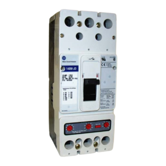
Figure 1-1 J D -Frame Motor Circuit Protector
40752-165(1)
Effective March 2008
WARNING
The recommendations and information contained herein
are based on Allen-Bradley experience and judge-
ment, but should not be considered to be all-inclusive or
covering every application or circumstance which may
arise. If any questions arise, contact Allen-Bradley for
further information or instructions.
1. INTRODUCTION
General Information
The JD-frame instantaneous (magnetic)-only
motor circuit protector (MCP) (Fig. 1-1 ) has a rating of
250A for application with NEMA motor starter sizes 4
and 5. The MCP is available in 3-pole frames
only. The MCP is designed to comply with the
applicable requirements of Underwriters Laboratories,
Inc. Standard UL489 and the International
Electrotechnical Commission Recommendations No.
IEC 157-1 .
The MCP is a UL-recognized component under file
E7819. It is used primarily to provide short-circuit pro-
tection as part of a combination controller where other
circuit protective functions are performed by other
devices within the controller. Since the JD-frame MCP is
a non-sealed device, it is marked LINE and LOAD and
is not suitable for reverse feed applications.
This instruction leaflet (IL) gives procedures for installa-
tion, operation, inspection, and field testing of JD-frame
MCPs. For this publication, the term motor circuit
protector (MCP) shall also include instantaneous (mag-
netic)-only circuit interrupters.
2. INSTALLATION
The installation procedure consists of inspecting the
MCP and, as applicable, installing accessories, inter-
phase barriers and terminals; mounting the MCP; con-
necting the line and load conductors; torquing terminals;
and attaching terminal shields. The MCPs, accessories,
mounting hardware, and unmounted terminals may be
supplied in separate packages.
BUL. 140M
!
Advertisement
Table of Contents

Related Manuals for Allen-Bradley 140M


Summary of Contents for Allen-Bradley 140M
- Page 1 DO NOT ATTEMPT TO INSTALL OR PERFORM arise. If any questions arise, contact Allen-Bradley for MAINTENANCE ON EQUIPMENT WHILE IT IS ENER- further information or instructions.
- Page 2 Page 2 2-3. Install accessories. CAUTION WHEN REMOVED AND REINSTALLED, THREAD- NOTICE FORMING SCREWS WILL TRY TO REFORM THE THREADS IN THE BASE. CARE SHOULD BE TAKEN EVERY TIME A THREAD-FORMING SCREW IS USED TO ENSURE THE SCREW STARTS IN THE ORIGI- NAL THREADS.
- Page 3 Page 3 a. For individual surface mounting, drill mounting panel using the drilling plan shown in Fig. 2-3. For deadfront 1.375 .688 cover applications, cut out cover to correct escutcheon (34.37) (14.47) dimensions. (See Fig. 2-4.) b. If MCP includes factory- or field-installed internal 4.078 accessories, make sure that accessory wiring can be (103.58)
- Page 4 48.1 – 53.0 Handle Position Indicator Red – ON 53.1 – 57.6 Color White – TRIP 57.7 – 62.3 140M-JD8P-C80 750 62.4 – 67.3 Green – OFF (Reset) 67.4 – 71.9 72.0 – 76.9 77.0 – 81.6 1000 57.7 – 64.6 64.7 –...
- Page 5 These cir- cumstances could be beyond the control of the MCP so far as its allowable trip setting is concerned and should be treated as a special case, referable to Allen-Bradley. 40752-165(1) Effective March 2008...
- Page 6 Page 6 4. INSPECTION AND FIELD TESTING 4-2. Switch MCP to ON and OFF several times to be MCPs are designed to provide years of almost sure that the mechanical linkages are free and do not maintenance-free operation. The following procedure bind.
- Page 7 Page 7 NOTES 40752-165(1) Effective March 2008...
- Page 8 Page 8 40752-165(1) Effective March 2008 Printed in USA/TQC...
Need help?
Do you have a question about the 140M and is the answer not in the manual?
Questions and answers