
Related Manuals for F.u.n.k.e. TRT800A-OLED


Summary of Contents for F.u.n.k.e. TRT800A-OLED
- Page 1 TRT800A-OLED Mode-S Transponder P/N 800ATC-A-(2xx)-(3xx) Operation and Installation (Dokument-Nr. 03.2114.010.71e) f.u.n.k.e. means – fabrication · utilities · network · know-how · engineering k.e.
- Page 3 TRT800A / P/N 800ATC-A-(2xx)-(3xx) Operation and Installation Change History Revision Date Description of Change 1.00 04.02.2013 First Release Change of company name to 2.00 22.01.2014 f.u.n.k.e. AVIONICS GmbH Inserted new EM800-cable plan in chapter3.7.3 List of Service-Bulletins (SB) Service Bulletins have to be inserted into this manual and to be enlisted in the following table.
-
Page 4: Table Of Contents
TRT800A / P/N 800ATC-A-(2xx)-(3xx) Operation and Installation Table of Contents GENERAL ..................5 Symbols .................. 5 Abbreviations ................5 Customer Support ..............6 Features .................. 7 OPERATION ..................8 Controls ................... 8 ON/OFF ................10 Display Indications ..............11 Display - Brightness .............. 12 Flight-ID (FID) ............... - Page 5 TRT800A / P/N 800ATC-A-(2xx)-(3xx) Operation and Installation Antenna................. 23 3.8.1 Antenna Selection ............23 3.8.2 Installation Recommendation........23 3.8.3 Antenna Wiring ............23 Post-Installation Check............24 3.10 Starting Up ................24 3.11 Accessories ................25 3.12 Drawings ................26 3.12.1 Dimensions ..............26 3.12.2 Mounting Advices ............
-
Page 6: General
TRT800A / P/N 800ATC-A-(2xx)-(3xx) Operation and Installation GENERAL This manual contains information about the physical, mechanical and electrical characteristics and about installation and operation of the Mode S Transponder TRT800A. Symbols Advices whose non-observance can cause radiation damage to the human body or ignition of combustible materials Advices whose non-observance can cause damage to the device or other parts of the equipment. -
Page 7: Customer Support
TRT800A / P/N 800ATC-A-(2xx)-(3xx) Operation and Installation Customer Support In order to facilitate a rapid handling of return shipments, please follow the instructions of the input guide „Reshipment RMA“ provided at the Service-Area within the f.u.n.k.e. AVIONICS GmbH web portal www.funkeavionics.de. -
Page 8: Features
TRT800A / P/N 800ATC-A-(2xx)-(3xx) Operation and Installation Features In order to operate the Mode S transponder it is necessary to request an ICAO 24-bit Aircraft Address at the responsible national aviation authorities. The received Code is assigned to the specific transponder/aircraft and must be configured within the transponder. -
Page 9: Operation
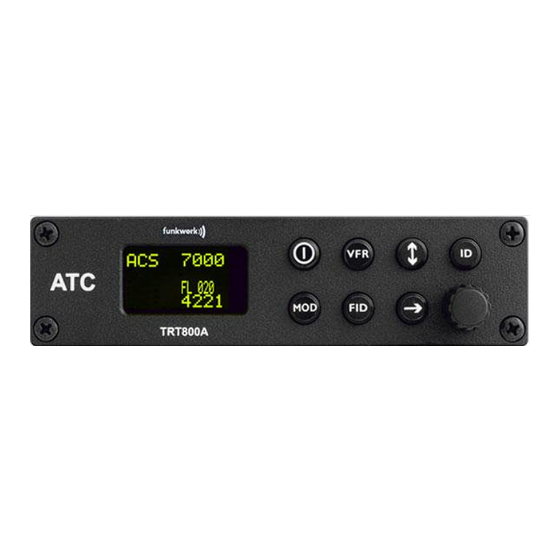
TRT800A / P/N 800ATC-A-(2xx)-(3xx) Operation and Installation OPERATION Controls Activate/ deactivate VFR Operation Mode Change (active) Active Standby Active Squawk Squawk ON / OFF „Squawk Ident“ Rotary Knob for adjusting values Standby at the cursor Operation Mode Flight-ID Squawk position (standby) (FID) Select Operation... - Page 10 TRT800A / P/N 800ATC-A-(2xx)-(3xx) Operation and Installation ► Switch ON press button for approx. 0,5 s ON/OFF ► Switch OFF press button for approx. 3 s ► activate/deactivate VFR Squawk (press shortly) ► store active Squawk as VFR/VFRW-Squawk (press button 3 s)( →2.8) change between active and standby-Squawk ►...
-
Page 11: On/Off
TRT800A / P/N 800ATC-A-(2xx)-(3xx) Operation and Installation ON/OFF Switch ON: press button for 0.5 s Switch OFF: press button for 3 s 2.2.1 Display information after power up After turning-on the display appears as follows (example): Device Name TRT800A. V5.3 Software Version FPGA-Vers: 102 Firmware Version... -
Page 12: Display Indications
TRT800A / P/N 800ATC-A-(2xx)-(3xx) Operation and Installation Display Indications Operational Mode: Lock out Reply Active Squawk Active indication indication Test mode 7000 indicatior PLL/TRX/ DC BAT/DIM Backlight setup FL 030 SPI indicator Low battery ind. STBY 2000 Flight level GND switch Operational Mode: Error Passive... -
Page 13: Display - Brightness
TRT800A / P/N 800ATC-A-(2xx)-(3xx) Operation and Installation Error indicators PLL Error Internal Error Transmit Failure Check antenna and wiring Low internal voltage Internal error FPGA-Failure Internal error Battery Power too low maybe battery/generator fault Display - Brightness In active mode (not standby) press -button for 2 s Adjust brightness (DIM) with rotary knob Return to normal operation: press... -
Page 14: Configure Flight-Id
TRT800A / P/N 800ATC-A-(2xx)-(3xx) Operation and Installation 2.5.2 Configure Flight-ID Press (repeatedly) until „STBY“ appears Press and hold ; while a counter is shown beside the active squawk, release when “CHANGE FID” is displayed CHANGE FID _ _ _ _ _ _ _ _ A B C D E F G H exit Enter Flight-Id with cursor button... -
Page 15: Squawk-Setting
TRT800A / P/N 800ATC-A-(2xx)-(3xx) Operation and Installation If no 24-bit address (AA) was defined or entered as “000000“ the transponder operates as a Mode A/C transponder, in that case the following Modes are possible apart from Standby: • A C – „Mode A+C“... -
Page 16: Id - Special Position Identification (Spi): "Squawk Ident
TRT800A / P/N 800ATC-A-(2xx)-(3xx) Operation and Installation • Display Standby Squawk: or use the rotary knob Press (the VFR-Squawk remains active!) Example: 4700 7000 7000 FL 030 FL 030 FL 030 STBY 5600 STBY STBY 4700 • Now the Standby Squawk can be adjusted by using the rotary knob and activated with •... -
Page 17: Installation
TRT800A / P/N 800ATC-A-(2xx)-(3xx) Operation and Installation INSTALLATION Notes The following suggestions should be considered before installing. The assigned installation company will supply wiring. For diagrams refer to 3.7 Wiring. Transponder, External Memory, all cables and antennas shall be installed according to „FAA AC-143.13-2A Acceptable Methods, Techniques and Practices –... -
Page 18: Unpacking And Inspection Of The Equipment
TRT800A / P/N 800ATC-A-(2xx)-(3xx) Operation and Installation Unpacking and Inspection of the Equipment Carefully unpack the equipment and inspect for transport damages. If a damage claim has to be filed, save the shipping container and all packing materials as evidence to your claim. For storage or reshipment the original packaging should be used. -
Page 19: Equipment Connections
TRT800A / P/N 800ATC-A-(2xx)-(3xx) Operation and Installation Equipment Connections 3.6.1 Electrical Connections One 15 pin D-SUB miniature connector includes all electrical connections, except for the antenna. Use only an External Memory TRT800EMxx as this is part of the certification and includes a memory device in which the ICAO 24-bit Aircraft Address is stored. -
Page 20: Static Air Port
TRT800A / P/N 800ATC-A-(2xx)-(3xx) Operation and Installation 3.6.2 Static Air Port Install a silicon soft tube fitting the 5 mm static air hose at the backside of the transponder and secure plumbing with appropriate clamps. Wiring 3.7.1 Conductor Cross Section Power Supply (Power, GND): AWG20 (0,62 mm²) Signals:... - Page 21 TRT800A / P/N 800ATC-A-(2xx)-(3xx) Operation and Installation Ground Switch/ If an external Ground Switch is connected, it must connect this pin to GND to indicate the on-ground FLY-GND condition. Leave open otherwise. Adaptors Previous adaptor version does not provide full interface TRT800EM &...
-
Page 22: Cable Plan External Memory Em800
TRT800A / P/N 800ATC-A-(2xx)-(3xx) Operation and Installation 3.7.3 Cable plan External Memory EM800 3.7.3.1 Cable plan TRT800EMRS (older version) to S/N 90932013 DSUB 15pol white < PIN-5 > black open < PIN-12> yellow cable < PIN-15> FLY_GND ends < PIN-13> SUPP_I/O shield black... - Page 23 TRT800A / P/N 800ATC-A-(2xx)-(3xx) Operation and Installation 3.7.3.2 Cable plan TRT800EMRS (newer version) from S/N 90932114 DSUB 15pol white < PIN-5 > brown open < PIN-12> yellow cable < PIN-15> FLY_GND green ends < PIN-13> SUPP_I/O shield brown RMT-TXD < PIN-7 > white RMT-RXD Remote Binder...
-
Page 24: Antenna
TRT800A / P/N 800ATC-A-(2xx)-(3xx) Operation and Installation Antenna 3.8.1 Antenna Selection • Recommended antennas: see section 3.11 Accessories • Choose an antenna type compatible with the vehicle and the mounting location. • Specified features depend on proper installation of the antenna. •... -
Page 25: Post-Installation Check
TRT800A / P/N 800ATC-A-(2xx)-(3xx) Operation and Installation Attenuation from antenna to transponder at 1090 MHz must not exceed 1.5 dB! Post-Installation Check A certified maintenance shop must verify proper operation of the transponder by testing in accordance with Appendix F of “14 CFR Part 43–... -
Page 26: Accessories
TRT800A / P/N 800ATC-A-(2xx)-(3xx) Operation and Installation 3.11 Accessories Part Number Description TRKABEL2 Antenna cable 2,5 m (8.2 ft) BNC, RG-142, 1,075 dB TRKABEL3 Antenna cable 4,0 m (13.2 ft) BNC, RG-142, 1,72dB TRKABEL4 Antenna cable 6,5 m (21.3 ft) BNC, RG-142, 2,8 dB CI-105 Transponder/DME Antenna TSO C66b, C74c... -
Page 27: Drawings
TRT800A / P/N 800ATC-A-(2xx)-(3xx) Operation and Installation 3.12 Drawings 3.12.1 Dimensions 14 mm Fixing clips (spring) left / right 15 mm 20 mm 140 mm 160 mm O 4,3 mm 148 mm Connector (plug) has to be clamped with both spring locks Document-No: 03.2114.010.71e / Revision: 2.00... -
Page 28: 3.12.2 Mounting Advices
TRT800A / P/N 800ATC-A-(2xx)-(3xx) Operation and Installation 3.12.2 Mounting Advices Panel cut-out: 160 x 42 mm, horizontal aligned, in viewable and reachable position to the pilot There are three alternative ways of mounting: • Mounting directly at the panel: Use the standard mounting blocks of Mounting Block Set MB800AS (included in delivery). - Page 29 TRT800A / P/N 800ATC-A-(2xx)-(3xx) Operation and Installation Spacer Plate Distanzblech KT76 frame remains in the panel KT76-Rahmen bleibt montiert (Mounting-Block-Set MB800KT) KT76 frame removed KT76 Rahmen entfernt (Mounting-Block-Set MB800A2) 148 mm 158 mm direct panel mounting Befestigung direkt am Panel (Mounting-Block-Set MB800AS) Document-No: 03.2114.010.71e / Revision: 2.00...
-
Page 30: Transponder Settings
TRT800A / P/N 800ATC-A-(2xx)-(3xx) Operation and Installation TRANSPONDER SETTINGS Overview The TRT800A is capable of storing the following information: • ICAO 24-Bit Aircraft-Address (AA) • Aircraft Category (AC), • Flight Identification (FID) • Ground-Switch (Yes/No) • Speed Category (RI) • RS232 Interface Configuration All of these data are configurable in the Setup and are stored in the external memory module integrated within the housing of the D-Sub connector (included in the delivery). - Page 31 TRT800A / P/N 800ATC-A-(2xx)-(3xx) Operation and Installation Display (Example) Page 1 Aircraft Address AA : F E 1 2 3 4 Aircraft Category AC : FID: 4 4 E 1 2 3 Flight Identification MOD= next Page 2 Speed Category Speed Cat : 8 Ground Switch option Ground Sw.: YES...
-
Page 32: General Settings
TRT800A / P/N 800ATC-A-(2xx)-(3xx) Operation and Installation • a GPS protocol is set as interface protocol (NMEA / FREEFLIGHT / AR-NAV) • GPS receiver is connected and transmits data (if not: “Pos. :no data” is displayed) • a valid position is transmitted (if not: “Pos. :wrong data” displayed). -
Page 33: Flight-Id (Fid)
TRT800A / P/N 800ATC-A-(2xx)-(3xx) Operation and Installation 4.3.3 Flight-ID (FID) Setup→4.5.4 Per ICAO regulation Mode-S data must contain a valid flight identification (FID), to ensure that the correlation between flight plan and radar data will work automatically. FID setting is required to correspond to the aircraft identification that has been specified at item 7 of the ICAO flight plan. -
Page 34: Reply Information - Speed Category (Ri)
TRT800A / P/N 800ATC-A-(2xx)-(3xx) Operation and Installation 4.3.4 Reply Information – Speed Category (RI) Setup→4.5.4 Besides AA, AC and FID another important part of the Mode-S data is the Speed Category of the respective aircraft. This speed category shall be configured in the setup (see 4.5.4) and must contain one of the following codes. -
Page 35: Option Remote Header
TRT800A / P/N 800ATC-A-(2xx)-(3xx) Operation and Installation 4.4.2 Option Remote Header Setup→4.5.4 Wiring→3.7.3 The transponder provides a TRT800RT remote control interface. If a remote header TRT800RT is connected transponder can be remote controlled via this interface. Remote interface provides control of all standard user inputs available during standard operational mode. -
Page 36: Altitude Correction/Offset
TRT800A / P/N 800ATC-A-(2xx)-(3xx) Operation and Installation Option Description Baud rate FAVISIA Glass Cockpit support FAVISIA Data format to be processed in FAVISIA avionics suite. FAVISIA+GPS Data format to be processed in FAVISIA 4800 avionics suite (output) and additional processing of incoming NMEA GPS- Receiver position data to support the ADS-B Out functionality Other... -
Page 37: Setup Procedure
TRT800A / P/N 800ATC-A-(2xx)-(3xx) Operation and Installation The check for correspondence between the primary altimeter and the TRT800A is usually performed every 24 months as part of the aircraft's altimeter checks. Altitude correction is based on setup configurable offset values at five interpolation points ( 2000, 10000, 18000, 25000 and 35000 ft). -
Page 38: Transponder Configuration/Record Structure
TRT800A / P/N 800ATC-A-(2xx)-(3xx) Operation and Installation 4.5.2 Transponder configuration/record structure Aircraft related parts of transponder configuration are stored in one out of eight possible records (record=presetting). Each record contains the following information: • Aircraft Address (AA, 24bit) • Aircraft category (AC) •... -
Page 39: General Setup
TRT800A / P/N 800ATC-A-(2xx)-(3xx) Operation and Installation 4.5.4 General Setup Any menu item can be passed by . If no changes are made the original settings will remain stored. Modification of one menu item does not impact the others. No entries will be deleted. - Page 40 TRT800A / P/N 800ATC-A-(2xx)-(3xx) Operation and Installation Step Display (Example) Record 1: With the rotary knob you can select „yes“ if a Ground Switch is installed, if not select “no” and proceed with GND Switch: Yes/No MOD=next step 7 Record 1: At this stage the respective speed category shall be selected by using Speed Cat.:...
-
Page 41: Altitude Correction Setup
TRT800A / P/N 800ATC-A-(2xx)-(3xx) Operation and Installation Step Display (Example) 10. With further Records can now be Records created and configured as described ID=Edit Records in the aforementioned steps At start-up of the transponder one of MOD=Exit the defined records with all associated configurations need to be selected 2000... - Page 42 TRT800A / P/N 800ATC-A-(2xx)-(3xx) Operation and Installation Altitude correction is based on five interpolation points ( 2000, 10000, 18000, 25000 and 35000 ft).The offset value at each interpolation point can be adjusted in a range from -100 to + 100ft at each point (10ft steps). Offset values set to zero at each interpolation point deactivates altitude correction (default/factory setting).
- Page 43 TRT800A / P/N 800ATC-A-(2xx)-(3xx) Operation and Installation Step Display (Example) 6. (..9) Repeat last step for another 4 altitude levels Altitude: 35000 ft 10000ft 18000ft Offset 10 ft 25000ft 35000ft MOD=next/Exit /exit 10. You have now left the configuration 2000 mode and are back in normal operation.
-
Page 44: Appendix
TRT800A / P/N 800ATC-A-(2xx)-(3xx) Operation and Installation APPENDIX Technical Data Compliance CS-ETSO-2C112a EASA.21O.268 Applicable Documents CS-ETSO-2C112a EUROCAE ED-73B Class 1 Level 2es EUROCAE ED-26 RTCA DO-160D RTCA DO-178B Software-Level D Temperature Ranges Operation -20 °C to +55 °C; for 30 min +70°C Storage -55 °C to +85 °C Altitude Range... -
Page 45: Environmental Conditions
TRT800A / P/N 800ATC-A-(2xx)-(3xx) Operation and Installation Reply transmission 1090 ± 1 MHz frequency ≥ 21 dBW (126 W) at antenna base RF Peak Power Output (with maximum cable attenuation of 1,5 dB) Squitter (ADS-B) transmitted at random intervals uniformly distributed over the range from 0.8 to 1.2 seconds, full self-verification of data and occurrence... - Page 46 TRT800A / P/N 800ATC-A-(2xx)-(3xx) Operation and Installation Sectio Characteristic DO–160D Cat. Condition Altitude 4.6.1 35 000 ft 2°C change rate minimum Temperature Variation per minute Humidity 6 G operational shocks 20 G Crash Safety Shock Test Type R in all 6 directions Vibration Vibration Curve M...
- Page 47 TRT800A / P/N 800ATC-A-(2xx)-(3xx) Operation and Installation Notes: Document-No: 03.2114.010.71e / Revision: 2.00...
- Page 48 f.u.n.k.e. AVIONICS GmbH Heinz-Strachowitz-Str. 4 DE-86807 Buchloe Germany phone.: +49-8241 80066 0 fax.: +49-8241 80066 99 E-mail: service@funkeavionics.de www.funkeavionics.de f.u.n.k.e. means – fabrication · utilities · network · know-how · engineering k.e.
Need help?
Do you have a question about the TRT800A-OLED and is the answer not in the manual?
Questions and answers