
Related Manuals for CAMSO DTS 129

Summary of Contents for CAMSO DTS 129
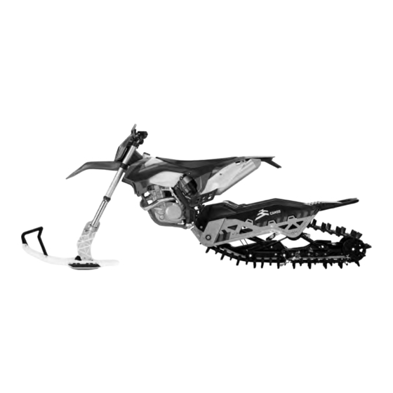
- Page 1 CAMSO DTS 129 CAMSO DTS 129 Dirt-to-snow Dirt-to-snow bike conversion system bike conversion system DTS 129: 1099-01-1840 DTS 129: 1099-01-1840 USER MANUAL 2018 USER MANUAL 2018...
- Page 2 Formerly Camoplast Solideal, Camso is the best of Camoplast and Solideal. To keep moving forward while staying true to our history, we're now Camso, the Road Free Company. WARNING Please read carefully each part of this document as well as model specific Installation Guidelines prior to assembling, installing and using the Conversion System.
-
Page 3: Table Of Contents
TABLE OF CONTENTS INTRODUCTION ................1 SYMBOLS AND SIGNAL WORDS . -
Page 4: Introduction
• This document is an integral part of the System. Pass it along to any new System owner. Thank you for choosing the Camso DTS 129 Dirt- • Consult legal authorities where you drive your To-Snow bike conversion system, (hereinafter motorcycle equipped with the System before referred to as the "System"). -
Page 5: Safety
Conversion System. CAUTION: Do not remove the warning stickers from the frame. If a sticker is damaged, have it replaced by an authorized Camso dealer. TENSIONER WARNING WARNING - STRUT ROD Tensioner Bolt Warning - If track tension adjustment is required, the tensioner assembly bolt must be loosened first. - Page 6 Insufficient knowledge of a motorcycle during down Camso DTS 129 System by Camso. It is hill riding, climbs and crossing of obstacles and mandatory that every user takes the time to turns can result in tipping or roll over, and can carefully read, understand and then consult this cause severe injuries.
-
Page 7: Operating Instructions
OPERATING INSTRUCTIONS OPERATING INSTRUCTIONS WARNING HINTS AND TIPS Riding a motorcycle equipped with a Conversion System is different from riding a two-wheeled • Before leaving for an excursion, make sure to motorcycle. It is strongly recommended that the bring with you the following: 13 mm, 15 mm, 16 safety guidelines provided below are followed to mm, wrenches and sockets, 3 and 6 mm Allen prevent any accident and/or serious malfunction... -
Page 8: Torque Specifications
• A Wheel kit is available to help move your M8-1.25 GR 10.9 33 N•m 24 lb-ft motorcycle fitted with a DTS 129 Conversion kit. M10-1.5 GR 8.8 50 N•m 37 lb-ft NOTE: The Wheel kit, shown below in Figure 4, can be M10-1.5... -
Page 9: Adjustments
ADJUSTMENTS ADJUSTMENTS CAUTION: Verification of adjustment settings on the system is mandatory after first use on the motorcycle. rubber track tension, suspension’s angle of attack and the tension in the drive chains must be re-checked. Incorrect adjustments can decrease system performance produce premature wear... -
Page 10: Drive Chain Tension
ADJUSTMENTS DRIVE CHAIN TENSION • Adjust next the tension in the secondary drive chain (1) by turning the vertical adjustment nut (2) on the chain tensioner. See Figure 9. • To make the following setting adjustments, the skin cover must be removed from the rear part of the system. -
Page 11: Suspension Adjustment
The suspension can be adjusted to fit the rider’s weight, personal preferences or type of use made of the vehicle. NOTE: Camso recommends that the suspension spring adjustment be made in a workshop/ garage before using the motorcycle. • Loosen the wheel assembly bolt (1) located... - Page 12 ADJUSTMENTS • Position Tension Cam in its seat on the suspension arm. Move cam forward or WARNING backward depending on the level of stiffness Suspension spring tension is very high. Handle desired in the suspension. See Figure 17. with care and use appropriate tools to avoid any risk of injury during spring calibration.
-
Page 13: Suspension - Limiter Cable Adjustment
ADJUSTMENTS SUSPENSION - LIMITER CABLE • Re-install bolt that was removed to complete adjustment. Figure 20. ADJUSTMENT Upon reception of the Conversion kit, you will find the suspension limiter cables adjusted to the short position. To adjust limiter cables to the long position, proceed as follows: •... -
Page 14: Rubber Track Tension
DEFLECTION = 19 mm [¾ in.] Figure 25 NOTE: The track tension testing tool shown below in Figure 26 can be purchased through an authorized Camso dealer. The part number is 2000-00-3125. Figure 24 Figure 26 CAUTION: Make sure to re-tighten Track Tensioner assembly bolt (A) and jam nut (B) after completing track tension adjustment. -
Page 15: Maintenance
MAINTENANCE MAINTENANCE The maintenance schedule has been established WARNING in order to provide optimum durability for your Do not insert hands or feet into or near the System. The type of usage and the conditions in System unless the engine is off, and the vehicle is which the System is used, have a direct bearing stopped with the security brake engaged. - Page 16 MAINTENANCE MAINTENANCE - TASKS • Chains - Wear: Verify wear and general condition of chains in drive mechanism. Refer • Inspect: Component(s) must be examined to “Wear” in the Maintenance section on with care. If an anomaly is noticed, the page 17.
- Page 17 MAINTENANCE • Wear: Verify wear and overall condition of the System’s rubber track. Refer to “Wear” in the • Carbide Runners: Inspect general condition of Maintenance section on page 18. Carbide Runners. Replace Carbide Runners if they show signs of damage or deformation. CAUTION: A damaged track can result Refer to “Wear”...
-
Page 18: Lubrication
MAINTENANCE LUBRICATION CHAIN TENSIONER SUSPENSION ARMS SHOCK ABSORBER CHAINS WHEEL SHAFTS... - Page 19 MAINTENANCE LUBRICATION NOTE: Tension in the Suspension torsion spring must be released before attempting to remove the The maintenance chart on page 12 contains side panels to grease the suspension arm lubrication maintenance to be performed on shafts. System. Refer following recommendations for optimal lubrication.
-
Page 20: Wear
MAINTENANCE REFERENCE “E” WEAR WHEEL SHAFTS Wheels Apply 1-2 cc of grease evenly all around and Verify the general condition of the suspension’s along the length of wheel shafts (E). wheels. If they show important wear or missing fragments, replace the wheel. Check wheel bearings for restriction, noise or abnormal play in rotation. - Page 21 MAINTENANCE Track Rubber Dampers (anti-rotation) Verify wear on Track by inspecting the internal (A) Inspect the Rubber Dampers (A) mounted on and external (B) condition of the Track's carcass strut rod. Replace them if they show cracks or are rolling path, driving lugs (C), the profile (D). Make excessively worn or deformed.
- Page 22 MAINTENANCE Brake Pads Nylon Protector and Guides - chains Inspect brake pads (A) for wear. If pad thickness Replace nylon protector and guides when they is under 1.6 mm (1/16 in.), replace the parts. See are worn out and let the chain pass too near the Figure 33.
- Page 23 MAINTENANCE Suspension Cables Carbide Runners Inspect condition of Suspension Cables (A). If it If the ski lacks support through turns on ice, check shows abnormal wear broken strands condition of carbide runners (A). If carbide inserts anywhere along its length, replace the cables. (B) show abnormal wear, cracks or missing Verify that the sleeves (B) are in good condition fragments, replace the parts.
-
Page 24: 2-Year Limited Warranty
Camso guarantees that the new, unused Camso loading, including excessive number of passengers. DTS 129 System (System) installed by an authorized dealer or distributor is free from any defects in 6) Labor costs, parts and materials related any and all materials and workmanship during the period and in maintenance costs. -
Page 25: Troubleshooting
TROUBLESHOOTING TROUBLESHOOTING... - Page 26 TROUBLESHOOTING...
-
Page 27: Parts List
PARTS LIST ITEM PART # DESCRIPTION CAMSO DTS 129 MY2018 :: FRONT SKI ASSEMBLY 1032-10-H030 HSCS, M10-1.5X30, 12.9, ZP, TL, DIN 912 1035-08-C050 HFCS, M8-1.25X50, 10.9, ZP, IFI536 1036-10-4030 HFSCS, M10-1.5X30, 10.9, ZP, TL, DIN 6921 1038-08-K020 HSFBS, M8-1.25X20, SS, 18-8 1060-00-0001 W, 11/16X11/32X0.060, 8, ZP, SAE... - Page 28 PARTS LIST ITEM PART # DESCRIPTION CAMSO DTS 129 MY2018 :: REAR SUSPENSION 1016-00-9162 IDLER WHEEL 162MM / ROUE INTERMÉDIAIRE 162MM 1032-04-J010 SHCS, M4-0.7X10, 12.9, ZP, DIN912 1033-06-0150 HCS, M6-1.0X150, 8.8, ZP, ISO4014 1035-10-1045 HFCS, M10-1.5X45, 10.9, ZP, DIN6921 1036-08-0025 HFSCS, M8-1.25X25, 8.8, ZP, DIN6921 1036-10-4030 HFSCS, M10-1.5X30, 10.9, ZP, TL, DIN6921...
- Page 29 PARTS LIST ITEM PART # DESCRIPTION CAMSO DTS 129 MY2018 :: FRAME ASSEMBLY 1009-00-9019 SPROCKET, 520, 19 TEETH / BARBOTIN, 520, 19 DENTS 1033-10-2026 HCSW, M10-1.5X25, 8.8, ZP, TL, DIN933 1035-12-1100 HFCS, M12-1.75X100 ,10.9, ZP, DIN6921 1036-08-0025 HFSCS, M8-1.25X25, 8.8, ZP, DIN6921 1046-08-0020 CB, M8-1.25X20, 8.8, ZP...
- Page 30 PARTS LIST ITEM PART # DESCRIPTION CAMSO DTS 129 MY2018 :: REAR SUSPENSION ASSEMBLY 7087-00-9024 S-KIT, SUSPENSION ASSY/ SUSPENSION ASSEMBLÉE 1036-10-4030 HFSCS, M10-1.5X30, 10.9, ZP, TL, DIN 6921 1060-00-0004 W, 7/16X1.0X0.072, 8, ZP, USS REAR SUSPENSION, SUB ASSY / SOUS-ENS, SUSP. ARRIÈRE...
- Page 31 PARTS LIST ITEM PART # DESCRIPTION CAMSO DTS 129 MY2018 :: FRONT SUSPENSION ARM 7087-00-9355 S-KIT, FRONT SUSPENSION ARM / BRAS SUSPENSION AVANT 1036-10-4030 HFSCS, M10-1.5X30, 10.9, ZP, TL, DIN 6921 1060-00-0004 W, 7/16X1.0X0.072, 8, ZP, USS FRONT SUSPENSION A-ARM / BRAS SUSPENSION AVANT...
- Page 32 PARTS LIST ITEM PART # DESCRIPTION CAMSO DTS 129 MY2018 :: REAR SUSPENSION ARM 7087-00-9290 S-KIT, REAR SUSPENSION ARM / BRAS SUSPENSION ARRIERE 1016-00-9162 IDLER WHEEL, 162MM / ROUE INTERMÉDIAIRE, 162MM 1036-10-4030 HFSCS, M10-1.5X30, 10.9, ZP, TL, DIN 6921 1060-00-0004 W, 7/16X1.0X0.072, 8, ZP, USS REAR SUSPENSION A-ARM / BRAS SUSPENSION ARRIÈRE...
- Page 33 PARTS LIST ITEM PART # DESCRIPTION CAMSO DTS 129 MY2018 :: TORSION SPRING 7080-00-9006 S-KIT, TORSION SPRING / RESSORT DE TORSION TORSION SPRING / RESSORT DE TORSION 1087-00-9053 SPRING HOLDER / SUPPORT RESSORT 1087-00-9154 SLEEVE / MANCHON 1092-00-9033 SPRING CAM / CAME, RESSORT...
- Page 34 PARTS LIST ITEM PART # DESCRIPTION CAMSO DTS 129 MY2018 :: 200MM WHEEL ASSEMBLY 7016-00-9200 S-KIT, WHEEL 200MM / ROUE 200MM WHEEL 200MM / ROUE 200MM 1036-08-0025 HFSCS, M8-1.25X25, 8.8, ZP, DIN6921 1060-08-0001 W, 24X8.4X2, ZP, DIN9021 ITEM PART #...
- Page 35 PARTS LIST ITEM PART # DESCRIPTION CAMSO DTS 129 MY2018 :: SUSPENSION RAIL 7087-00-9080 S-KIT, SUSPENSION RAIL ASSY / RAIL SUSPENSION ASS. 1033-06-0150 HCS, M6-1.0X150, 8.8, ZP, ISO4014 1036-08-0025 HFSCS, M8-1.25X25, 8.8, ZP, DIN6921 1060-06-0001 W, 6.4X20X1.5, ZP, DIN9021 1074-06-0001 FNN, M6-1, 8, ZP, DIN6926...
- Page 36 1036-12-4030 HFSCS, M12-1.75X30, 10.9, ZP, TL, DIN 6921 1047-16-1065 ROD END, M16-1.5X65, ASSY / TIGE EMBOUT, M16-1.5X65, ASS 1051-00-9030 SPACER, ANTI-ROTATION / ESPACEUR ANTI-ROTATION 1093-00-9060 RUBBER DAMPER / AMORTISSEUR DE CAOUTCHOUC TAG - STRUT ROD DTS 129 / ÉTIQUETTE - BRAS COUPLAGE DTS 129...
- Page 37 1178-08-0001 CLN, M8-1.25, BP ITEM PART # DESCRIPTION CAMSO DTS 129 MY2018 :: DRIVE SIDE BEARING ASS’Y 7090-00-9205 S-KIT, BEARING DRIVE SIDE /ROULEMENT, CÔTÉ ENTRAÎNEMENT 1033-10-2026 HCSW, M10-1.5X25, 8.8, ZP, TL, DIN933 1046-08-0020 CB, M8-1.25X20, 8.8, ZP 1074-08-0001 FNN, M8-1.25, 8, ZP, DIN6926...
- Page 38 AXLE SHAFT / ARBRE D’ENTRAÎNEMENT ITEM PART # DESCRIPTION CAMSO DTS 129 MY2018 :: BRAKE SIDE BEARING ASS’Y 7086-00-9004 S-KIT, BEARING BRAKE SIDE / ROULEMENT, CÔTÉ FREIN 1033-10-2026 HCSW, M10-1.5X25, 8.8, ZP, TL, DIN933 1036-08-0025 HFSCS, M8-1.25X25, 8.8, ZP, DIN6921 BRAKE CARRIER / SUPPORT ÉTRIER FREIN...
- Page 39 PARTS LIST ITEM PART # DESCRIPTION CAMSO DTS 129 MY2018 :: BRAKE ROTOR ASS’Y 7086-00-9023 S-KIT, BRAKE ROTOR ASSY / ENSEMBLE ROTOR FREIN 1032-06-J020 SHCS, M6-1X20, 12.9, ZN, DIN912 BRAKE ROTOR / DISQUE DE FREIN ROTOR HUB / MOYEU DE ROTOR...
- Page 40 ITEM PART # DESCRIPTION CAMSO DTS 129 MY2018 :: RIGHT SIDE PANEL 7018-00-9025 S-KIT, DTS SIDE PANEL - RH / PANNEAU LATÉRAL DROIT 1017-00-9026 SQUARE RIBBED PLUG / CAPUCHON TUBE CARRÉ SIDE PANEL, RH, ASS’Y / PANNEAU LATÉRAL DROIT ASSEMBLÉ...
- Page 41 PARTS LIST ITEM PART # DESCRIPTION CAMSO DTS 129 MY2018 :: LEFT SIDE PANEL 7018-00-9015 S-KIT, DTS SIDE PANEL - LH / PANNEAU LATÉRAL GAUCHE TENSIONER, PLATE / TENDEUR, PLAQUE 1017-00-9026 SQUARE RIBBED PLUG / CAPUCHON TUBE CARRÉ SIDE PANEL, LH, ASSY / PANNEAU LATÉRAL GAUCHE ASSEMBLÉ...
- Page 42 ITEM PART # DESCRIPTION CAMSO DTS 129 MY2018 :: CHAIN TENSIONER ASS’Y 7014-00-9180 S-KIT, DTS CHAIN TENSIONER / TENDEUR CHAÎNE DTS 1009-00-9015 SPROCKET, 520, 15 TEETH / BARBOTIN, 520, 15 DENTS 1009-00-9017 SPROCKET, 520, 17 TEETH / BARBOTIN, 520, 17 DENTS TENSIONER, CHAIN / TENDEUR DE CHAÎNE...
- Page 43 ITEM PART # DESCRIPTION CAMSO DTS 129 MY2018 :: CHAIN SPROCKETS 1009-00-9019 SPROCKET, 520, 19 TEETH / BARBOTIN, 520, 19 DENTS 1009-00-9017 SPROCKET, 520, 17 TEETH / BARBOTIN, 520, 17 DENTS 1009-00-9015 SPROCKET, 520, 15 TEETH / BARBOTIN, 520, 15 DENTS...
- Page 44 PARTS LIST ITEM PART # DESCRIPTION CAMSO DTS 129 MY2018 :: CHAIN GUIDE KIT 7085-00-9061 S-KIT, CHAIN GUIDE SET / ENS. GUIDE CHAÎNE CHAIN GUIDE / GUIDE DE CHAÎNE SLEEVE, NYLON / DOUILLE, NYLON BLOCK, CHAIN GUIDE / BLOC, GUIDE DE CHAÎNE 1278-08-X029 RN, M8-1.25, 0.5-7.1, ZP...
- Page 45 PARTS LIST ITEM PART # DESCRIPTION CAMSO DTS 129 MY2018 :: BRAKE SYSTEM 7086-00-9070 S-KIT, BRAKE SYSTEM DTS / S-KIT, SYSTÈME FREIN DTS 1032-08-J065 HSCS, M8-1.25X65, 12.9, ZN, DIN912 1037-00-0003 MOUNTABLE CABLE TIE / ATTACHE CÂBLE 1037-00-0037 LOOP CLAMP / BRIDE DE FIXATION...
- Page 46 PARTS LIST ITEM PART # DESCRIPTION CAMSO DTS 129 MY2018 :: UPRIGHT 7085-00-9150 S-KIT, UPRIGHT ASSY / S-KIT, SUPPORT ASSEMBLÉ SKI, UPRIGHT - WHITE / SKI, SUPPORT - BLANC SKI, UPRIGHT ROD / SKI, ARBRE SUPPORT SKI, UPRIGHT TUBE / SKI, TUBE SUPPORT...
- Page 47 PARTS LIST ITEM PART # DESCRIPTION CAMSO DTS 129 MY2018 :: PIVOT PLATE SET 7085-00-9040 S-KIT, SKI PIVOT PLATE SET / S-KIT, ENS. PLAQUE PIVOT SKI 1032-10-H030 HSCS, M10-1.5X30, 12.9, ZP, TL, DIN 912 SKI, PIVOT SKI, PIVOT THREADED / SKI, PIVOT FILETÉ...
- Page 48 PARTS LIST ITEM PART # DESCRIPTION CAMSO DTS 129 MY2018 :: CARBIDE RUNNER SET 7088-00-9055 S-KIT, SKI CARBIDE SET / S-KIT, ENS. CARBURE SKI 1060-00-0001 W, 11/16X11/32X0.060, 8, ZP, SAE 1074-08-0001 FNN, M8-1.25, 8, ZP, DIN6926 SKI RUNNER / LISSE SKI...
- Page 49 PARTS LIST ITEM PART # DESCRIPTION CAMSO DTS 129 MY2018 :: SKI RUBBER DAMPER 7093-00-0215 S-KIT, SKI RUBBER / S-KIT, CAOUTCHOUC SKI SKI, DAMPER / SKI, AMORTISSEUR 1096-00-0001 PN, 20X10X2, 2 ITEM PART # DESCRIPTION CAMSO DTS 129 MY2018 :: FRAME FASTENERS...
- Page 50 CAMSO DTS 129 MY2018 :: SUSPENSION FASTENERS 7000-00-9003 S-KIT, FASTENERS / BOULONNERIE - DTS SUSPENSION ITEM PART # DESCRIPTION CAMSO DTS 129 MY2018 :: SUSPENSION LIMITER CABLE 7003-00-9002 S-KIT, SUSPENSION LIMITER CABLE / S-KIT, CÂBLE LIMITEUR, SUSP. CABLE / CÂBLE 1032-04-J010 SHCS, M4-0.7X10, 12.9, ZP, DIN912...
- Page 51 PARTS LIST ITEM PART # DESCRIPTION CAMSO DTS 129 MY2018 :: WHEEL KIT 7200-00-9050 SKI, WHEEL KIT / ENSEMBLE DE ROUE, SKI 1016-00-2260 WHEEL (4.10/3.50-6) BLACK - ASS'Y / ROUE (4.10/3.50-6) NOIR - ASS. 1016-00-9200 WHEEL, 200 MM / ROUE, 200 MM...
Need help?
Do you have a question about the DTS 129 and is the answer not in the manual?
Questions and answers