Table of Contents
Advertisement
Quick Links
Advertisement
Table of Contents

Related Manuals for Audio Ltd. A10-RX-XLR

Summary of Contents for Audio Ltd. A10-RX-XLR
- Page 1 A10-RX Digital Wireless Receiver — — User Guide Models: A10-RX-SL and A10-RX-XLR...
-
Page 2: Table Of Contents
At the Receiver . . . . . . . . . . . . . . 4 A10-RX-XLR . . . . . . . . . . . . . . . 12 Connectors, Controls Description . -
Page 3: Overview
A10 system. It is designed to work with one or two A10-TX transmitters. It offers 224 MHz switching bandwidth and precision RF tracking filters in a lightweight, robust package. Two models are available, the A10-RX-SL for slot-in connection and the A10-RX-XLR for stand-alone operation with hardwired power and audio connections... -
Page 4: System Quickstart
A10-RX User Guide System Quickstart The A10 Digital Wireless System is easy to use Follow the steps below for basic setup and oper- ation At the Receiver 1 Fit the included straight and right-angled antennae to the A10-RX receiver 2 Connect the receiver to a power source It will immediately power on 3 Using the scanning tool in the Selection menu find an available open frequency. -
Page 5: Connectors, Controls Description
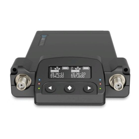
A10-RX User Guide Connectors, Controls Description Figure 1: A10-RX 1 -Antenna Socket 4 -Left Button SMA connector, 50 ohm, connects to includ- Moves the selection in menu to the left, or ed 1/4-wave whip antenna decrements values 2 -Channel Power LED 5 -Menu/Select Button Illuminates blue when the channel’s receiver Enters the menu selection Also used to select... -
Page 6: Powering
A10-RX User Guide Powering The A10-RX-SL receives power over its D-sub connector The A10-RX-XLR receives power from its 4-pin Hirose female connector The male Hirose connector is a power loop through When DC power is present, either at the D-sub connector or the Hirose 4-pin, the A10-RX is... -
Page 7: Main Display
A10-RX User Guide Main Display When the receiver is first powered on, the main display is in two-channel view. Two-Channel View The display shows channel 1 and channel 2 simultaneously Parameters displayed include the RF signal strength at each antenna, receiver frequency, audio level, and transmitter battery level. 1 -Channel 1 Settings 4 -Audio Level Bars indicates RF signal strength at each... -
Page 8: Rf Signal Indicator Leds
A10-RX User Guide RF Signal Indicator LEDs The RF Signal LEDs offer an at-a-glance indication of RF performance. The LEDs to the left of the display indicate channel 1 activity, whilst the LEDs to the right indicate channel 2 activity Each channel has one green LED and one red LED •... -
Page 9: Outputs Sub-Menu
A10-RX User Guide Outputs Sub-Menu Selections Icon Description Channel Options or Global Exit Returns to the main menu Max Level Selects the maximum analogue output level Output Channel • +14 dBu level based on a 0 dBFS signal sent from an A10-TX •... -
Page 10: System Sub-Menu
A10-RX User Guide System Sub-Menu ª All settings are Global. Selections Icon Description Options Exit Returns the main menu Power • 1 - channel 1 only Turns power to the RF receiver for each of the two channels on and off. •... -
Page 11: Frequency Scanning
44 1 kHz Channel 1 output appears at AES left, channel 2 appears at AES right With the A10-RX-XLR the channel 1 XLR connector is used for AES3 output The channel 2 XLR connector is not active when set to AES output... -
Page 12: Antennae
At present, updating the firmware on the A10-RX-SL requires converting from SL to XLR. Converting Between XLR and SL Mounts The A10-RX receiver is modular in design With the correct accessories—either the A-SL or the A-XLR adapters—the A10-RX-SL slot receiver and A10-RX-XLR cabled receiver can be con- verted between each type •... - Page 13 A10-RX User Guide 2 Remove the A-SL accessory 3 Position the A-XLR accordingly, and replace screws ª Complete the above procedure in reverse to convert from A10-RX-XLR to A10-RX-SL. - 13 -...
-
Page 14: Specifications
Specifications Frequency Range World Models: U S Only Models: A10-RX-SL (470–694 MHz) A10-RX-SL-US (470–608 MHz) A10-RX-XLR (470–694 MHz) A10-RX-XLR-US (470–608 MHz) Transmitters are tunable in 25 kHz steps Modulation Mode Audio Ltd proprietary digital RF modulation Digital Audio Codec Audio Ltd proprietary, high-performance digital encoding algorithm Audio Frequency Response 20 Hz–20 kHz... -
Page 15: A10-Rx-Sl Db-25 Connector Pin Assignments
A10-RX User Guide A10-RX-SL DB-25 Connector Pin Assignments The illustration below shows the pin assignments of the A10-RX-SL when viewing the bot- tom connector DB-25 Name Description Ground Ground connection Ch 1+ analogue / Ch 1,2 Ch 1 + analogue audio out, +2 dBu level (+/- 0 5 dB), balanced Alternately, Ch1 AES + and Ch 2 AES3+ (balanced, 110 ohm, transformerless) Ch 1 - analogue / Ch 1,2... -
Page 16: Certifications
A10-RX User Guide Certifications Industry Canada Conformity This radio transmitter has been approved by Industry Canada to operate with the supplied mono- pole whip antenna only Other antenna types are strictly prohibited for use with this device This device operates on a no-protection no-interference basis Should the user seek to obtain protection from other radio services operating in the same TV bands, a radio license is required. -
Page 17: Frequency Tables
A10-RX User Guide Frequency Tables The A10-TX offers preselected frequencies based on channels and sub channels. Three sets of frequencies are available based on either 6, 7, or 8 MHz channel bandwidth. Select the channel bandwidth based on the geographic region where the unit is operating X Frequencies (6 MHz Per TV Channel) The chart below shows all frequencies available for the A10 wireless system. -
Page 18: Y Frequencies (7 Mhz Per Tv Channel)
A10-RX User Guide Y Frequencies (7 MHz Per TV Channel) Sub Channels 485 3 485 7 486 1 486 3 486 7 487 1 487 3 487 7 488 1 488 3 488 7 489 1 489 3 489 7 490 1 490 3 490 7 492 3 492 7 493 1 493 3 493 7 494 1 494 3 494 7 495 1 495 3 495 7 496 1 496 3 496 7 497 1 497 3 497 7 499 3 499 7 500 1 500 5 500 7 501 1 501 3 501 7 502 1 502 5 502 7 503 1 503 3 503 7 504 1 504 5 504 7 506 3 506 7 507 1 507 5 507 9 508 3 508 3 508 7 509 1 509 5 509 9 510 3 510 3 510 7 511 1 511 5 511 9... -
Page 19: Z Frequencies (8 Mhz Per Tv Channel)
A10-RX User Guide Z Frequencies (8 MHz Per TV Channel) Sub Channels 470 2 470 6 471 0 471 4 471 8 472 2 472 6 473 0 473 4 473 8 474 2 474 6 475 0 475 4 475 8 476 2 476 6 477 0 477 4 477 8 478 2 478 6 479 0 479 4 479 8 480 2 480 6 481 0 481 4 481 8 482 2 482 6 483 0 483 4 483 8 484 2 484 6 485 0 485 4 485 8 486 2 486 6 487 0 487 4 487 8 488 2 488 6 489 0 489 4 489 8 490 2 490 6 491 0 491 4 491 8 492 2 492 6 493 0 493 4 493 8 494 2 494 6 495 0 495 4 495 8 496 2 496 6 497 0 497 4 497 8 498 2 498 6 499 0 499 4 499 8 500 2 500 6 501 0 501 4 501 8... - Page 20 A10-RX User Guide - 20 -...
Need help?
Do you have a question about the A10-RX-XLR and is the answer not in the manual?
Questions and answers