Advertisement
Quick Links
Download this manual
See also:
Service Manual
www.freeservicemanuals.info
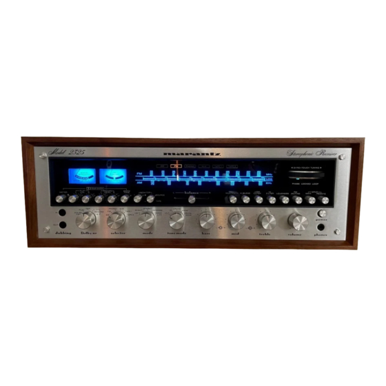
MARANTZ MODEL 2325 SERVICE MANUAL
INTRODUCTION
This service manual was prepared for use by Authorized Warranty Stations and contains
service information for the Marantz Model 2325 Stereophonic Receiver.
Servicing information and voltage date included in this manual are intended for use by the
knowledgeable and experienced technician only. All instructions should be read carefully. No
attempt should be made to proceed without a good understanding of the operation of the
receiver.
The parts list furnishes information by which replacement part may be ordered from the
Marantz Company. A belief description is included for parts which can be usually be obtained
through local suppliers.
1. SERVICE NOTES
As can be seen from the circuit diagram, the chassis of the Model 2325 consists of the
following units. Each unit mounted on a printed circuit board is drawn within bold dotted-line
block on the circuit diagram.
1. FM Front End ......................................................................
2. AM Tuner Unit ....................................................................
3. FM IF Amplifier ..................................................................
4. MPX Stereo Decoding Amplifier .........................................
5. Phono Amplifier ..................................................................
6. Dolby Unit...........................................................................
7. Power Amplifier...................................................................
8. Power Supply and Protection Relay Circuit........................
9. FM Cal. ................................................................................
10. Pre and Tone Amplifier .....................................................
11. Buffer Amplifier.................................................................
12. 400Hz Tone ......................................................................
13. 400Hz Tone, Tape 1 and 2 Tape Monitor Switch..............
14. Tape Monitor Assembly .....................................................
15. Multipath, Hi Blend, FM Muting, Low Filter,
Hi Filter, Loudness, Main Speaker and
Remote Speaker .........................................................................
16. Function Lamp ..................................................................
17. Dial Lamp ..........................................................................
2. AM TUNER
The AM Tuner section in the 2325 consists of one IC, including an RF amplifier, local
oscillator, mixer, IF amplifier, and detector, and three transistors, one of which forms a signal
strength indication amplifier and the other two form detected audio signal amplifier.
All components except the tuning capacitor and ferrite bar antenna are mounted on the
printed circuit board P150.
The AM signal induced in the ferrite bar antenna is fed to the RF amplifier input (Pin 12)
and amplified to the level required for overcoming conversion noises, thus giving good S/N
performance. The tuned circuit inserted in each of the output and input circuits of the RF
amplifier assures very high image and spurious rejection performance.
Thus the amplified and selected AM signal is then applied to one Mixer input (Pin 1).
While the local oscillator voltage is injected to the other Mixer input (Pin16) through a
capacitor C157. Then both AM signal and local oscillator output voltage are mixed and
converted into 455kHz intermediate frequency. The resulting IF signal is applied to the IF
transformer L153 consisting of one ceramic filter and two tuned circuits.
Digitized in Heiloo Netherland
Mounted on P.W. Board P100
Mounted on P.W. Board P150
Mounted on P.W. Board P200
Mounted on P.W. Board P300
Mounted on P.W. Board P400
Mounted on P.W. Board P600
Mounted on P.W. Board P700
Mounted on P.W. Board P800
Mounted on P.W. Board PC01
Mounted on P.W. Board PE01
Mounted on P.W. Board PH01
Mounted on P.W. Board PL01
Mounted on P.W. Board PS01
Mounted on P.W. Board PT01
Mounted on P.W. Board PU01
Mounted on P.W. Board PY01
Mounted on P.W. Board PZ01
5/30/2017
Advertisement

Related Manuals for Marantz 2325


Summary of Contents for Marantz 2325
- Page 1 1. SERVICE NOTES As can be seen from the circuit diagram, the chassis of the Model 2325 consists of the following units. Each unit mounted on a printed circuit board is drawn within bold dotted-line block on the circuit diagram.
- Page 2 3. FM TUNER The FM Tuner section in the Model 2325 consists of four functional blocks: FM Front End, IF Amplifier & Detector, Muting Control and MPX Stereo Decoding Circuit. An FM signal induced by the FM antenna is led to FM antenna coil L101 through the balun coil.
- Page 3 The muting circuit consisting of all solid-state electrical switching is incorporated in the Model 2325. Three input control the muting function. The first is related to signal strength; the second to the noise condition at the detector, and the third is derived from the DC component of the detector output.
- Page 4 www.freeservicemanuals.info 5/30/2017 The stereo composite signal from the buffer amplifier undergoes phase compensation by R301 and C201, is led through the muting switching FET H301 to the input terminal pin (2) of the MPX stereo decoding IC H321 on PLL (Phase Locked Loop) basis, and is decoded into the left and right stereo signals, which become available at pins (4) and (5), respectively.
- Page 5 www.freeservicemanuals.info 5/30/2017 This DC output is furnished through LPF-2 to the trigger amplifier which drives the stereo indicator lamp and stereo switch. Therefore, insufficient supply of the pilot signal results in failure to light the stereo indicator and to turn on the stereo switch located in the path of the 38kHz switching signal, thereby avoiding a wrong stereo operation.
- Page 6 7 or lower cycles per second. 9. DOLBY UNIT The Dolby unit built in the Model 2325, which is a switchable processor, is inserted in each of both R and L channels. The attached "DOLBY PROCESSING CHART" will facilitate you to well understand the operation of the Dolby circuit.
- Page 7 www.freeservicemanuals.info 5/30/2017 and is led to J611. The signal is then discriminated in the frequency and level by the dynamic filter consisting of H611, H613, H615 and H617, and is fed back to the mixing circuit. In the playback mode of operation, a part of the output signal (at J607) is led to J611 and discriminated in the frequency and level by the dynamic filter consisting of H611, H613, H615 and H617 and fed back to the mixing circuit.
- Page 8 www.freeservicemanuals.info 5/30/2017 15. 400Hz TONE SWITCH This is used for calibration of the record input level of the tape deck. When the switch is depressed, the built-in oscillator operates and a 580mV sine wave signal output will be fed to the four TAPE MONITOR OUT jacks.
-
Page 9: Test Equipment Required For Servicing
5/30/2017 17. TEST EQUIPMENT REQUIRED FOR SERVICING Table 1 lists the test equipment required for servicing the Model 2325 Stereophonic Receiver. Item Manufacturer and Model No. AM Signal Generator Signal source for AM align- ment. Test Loop Used with AM Signal generator. - Page 10 www.freeservicemanuals.info 5/30/2017 18.2 AM FREQUENCY RANGE AND TRACKING ALIGNMENT 1. Set an AM signal generator to 515kHz. Turn the tuning capacitor fully closed (with the tuning pointer placed at the low end.) and adjust the oscillator coil L152 for maximum audio output.
-
Page 11: Audio Adjustment
www.freeservicemanuals.info 5/30/2017 L or R channel (of course, the pilot signal must be included). 3. Adjust the trimming resistor R301 for maximum and same separation in both channels. 19.2 Muting Circuit Alignment 1. Connect a VTVM to the tap of the resistor R363 and adjust the resistor R363 until the meter reads 0.75V DC at no signal. - Page 12 Set the FM signal generator to 98MHz and the DOLBY switch to the OFF position. Turn the Tuning knob on Model 2325 until it tunes the 98MHz signal from the FM signal generator. Then, set the DOLBY switch to the DOLBY FM position, and adjust the FM preset level controls RC05 and RC06 until the DOLBY LEVEL meter may point the Dolby level.
- Page 13 www.freeservicemanuals.info 5/30/2017 23. DESCRIPTION OF DOLBY PROCESSING CHART This chart shows the condition of the signals available at the speakers (SPKRS) and at the TAPE MONITOR OUT terminals as a function of different control settings. To understand the chart refer to the symbols below: Represents a signal which has not been applied to either Record or Playback Dolby circuits.
- Page 14 www.freeservicemanuals.info 5/30/2017 Digitized in Heiloo Netherland...
- Page 15 5/30/2017 Marantz 2325 setup Automatic Voltage Regulator: Connect a DC volt meter between pins J804 and J805 and adjust R809 for 35v. DC Offset: Voltmeter between to the speaker terminals, adjust R713 for zero DC at the speaker terminals.
- Page 16 www.freeservicemanuals.info 5/30/2017 Digitized in Heiloo Netherland...
- Page 17 www.freeservicemanuals.info 5/30/2017 Digitized in Heiloo Netherland...
- Page 18 www.freeservicemanuals.info 5/30/2017 Digitized in Heiloo Netherland...
- Page 19 www.freeservicemanuals.info 5/30/2017 Digitized in Heiloo Netherland...
- Page 20 www.freeservicemanuals.info 5/30/2017 Digitized in Heiloo Netherland...
- Page 21 www.freeservicemanuals.info 5/30/2017 Digitized in Heiloo Netherland...
Need help?
Do you have a question about the 2325 and is the answer not in the manual?
Questions and answers
diagram of re stringing tuner dial