Table of Contents
Advertisement
Quick Links
Advertisement
Table of Contents

Related Manuals for Brigade MDR-504GW-500


Summary of Contents for Brigade MDR-504GW-500
- Page 1 Mobile Digital Recorder MDR-504GW-500 MDR-504G-500 MDR-504W-500 MDR-504-500 MDR-508GW-1000 MDR-508G-1000 MDR-508W-1000 MDR-508-1000 Installation and Operation Guide Please refer to www.brigade-electronics.com for most up-to-date data on all products Installation Guide 5145...
-
Page 2: Table Of Contents
Table of Contents 1 Introduction to MDR 500 Series Technology 8.2 Modules 1.1 Product Features 8.2.1 Mobile Network 1.1.1 Differences between MDR-504xx-500 and 8.2.2 Wi-Fi MDR-508xx-1000 8.2.3 GPS 1.1.2 Common to MDR-504xx-500 and MDR- 8.3 Server Status 508xx-1000 8.4 Environment 2 Kit Contents 8.5 Storage 2.1 MDR-504xx-500 and MDR-508xx-1000 Kits... -
Page 3: Introduction To Mdr 500 Series Technology
A brief description of each model is shown below: • MDR-504GW-500 - MDR 500 Series 4 Channel Mobile Digital Recorder with 500GB HDD, GPS, 4G, Wi-Fi and 32GB SD Card • MDR-508GW-1000 - MDR 500 Series 8 Channel Mobile Digital Recorder with 1000GB HDD, GPS, 4G, Wi-Fi and 64GB SD Card •... -
Page 4: Kit Contents
Kit Contents MDR-504xx-500 and MDR-508xx-1000 Kits 2.1.1 MDR-504xx-500 MDR 500 Series 4 Channel Control Unit with 500 GB HDD, GPS, 4G, Wi-Fi & 32GB SD Card (Depending on model) MDR-504xx-500-CU 2.1.2 MDR-508xx-1000 MDR 500 Series 8 Channel Control Unit with 1 TB HDD, GPS, 4G, Wi-Fi & 64GB SD Card (Depending on model) MDR-508xx-1000-CU 2.1.3 Common for MDR-504xx-500 and MDR-508xx-1000... -
Page 5: Optional Accessories
Optional Accessories 2.2.1 Remote Status & Interface Panel MDR Remote Status & Interface Panel MDR 6m Cable for Remote Status & Interface Panel MDR-RP-01-P MDR-06RPC 2.2.2 External G-Sensor MDR External G-Sensor (Non-IP rated) MDR 2m External G-Sensor Cable MDR-GS-02-G MDR-02GSC-02 Note: •... -
Page 6: Hardware Installation
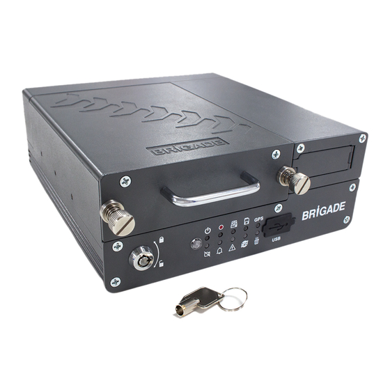
Hardware Installation Warning • Connecting any input or output wires to high voltages may damage the product. Brigade will not be responsible for any damage caused due to negligence. Front View 3.1.1 MDR-504xx-500 Front View Mobile Caddy Unit Handle Thumb screws... -
Page 7: Rear View
Rear View 3.2.1 MDR-504xx-500 Rear View GPS Connector (Mobile network and Wi-Fi 4 Channel SELECT depending on Type Camera model) Connectors Not Used Fireproof Box Input / Output Ethernet Cable Power Cable Connector Cable Connector Connector Connector MDR-504xx-500 Rear View Figure 3 Rear Panel: Mobile Network Antenna Connector Fireproof Box Connector... -
Page 8: Usb Mouse / Remote Control (Optional)
USB Mouse / Remote Control (Optional) Scroll Wheel / Third Mouse Button Right Mouse Button MDR-MOUSE-01 Figure 6 Power – No Function Number Keypad Used for either entering numerical values or to trigger individual camera views. Button 0 is used to either enter Navigation buttons are used browsing numerical value or to trigger split the OSD.Left Mouse Button... -
Page 9: Mdr-504Xx-500 Connection Diagram
MDR-504xx-500 Connection Diagram MDR-504xx-500 Connection Diagram Figure 8... -
Page 10: Mdr-508Xx-1000 Connection Diagram
MDR-508xx-1000 Connection Diagram MDR-508xx-1000 Connection Diagram Figure 9... -
Page 11: Mobile Caddy Unit Removal
Mobile Caddy Unit Removal Warning: Follow the removal steps shown below. Failure to do so over a prolonged period may damage the HDD. Ensure that the PWR LED indicates the MDR is OFF prior to removal. 3.7.1 MDR-504xx-500 MCU Removal Step 1 Unlock the MCU using the key Step 2... -
Page 12: Sd Card Removal
SD Card Removal Note: To remove an SD card from an MDR, the MCU needs to be removed first (see SD Card removal for MDR-504xx-500 Figure 12 and SD Card removal for MDR-508xx-1000 Figure 13). 3.8.1 MDR-504xx-500 SD Card Removal Step 1 Push the clip away from you while lifting the lid. -
Page 13: Mdr-508Xx-1000 Sim Card Installation/Expansion Module Upgrade
3.9.2 MDR-508xx-1000 SIM card Installation/Expansion Module Upgrade Step 2 Step 1 Ensure an earthing strap is worn to prevent any Remove the MCU and open the expansion damage to the PCB. Undo the screw on the module door to access the SIM card slot. rear panel (shown above left). -
Page 14: Mdr On-Screen Display (Osd)
MDR On-Screen Display (OSD) This chapter describes the configuration of the MDR. Brigade’s 500 Series MDR displays a start-up screen. See MDR Initialisation Screen Figure 16. During this period, the MDR completes a disk check which helps in identifying any file errors or bad sectors. -
Page 15: Login
Login By default, there are two user accounts: admin and user. The password for the admin account is admin. The password for the user account is user. Monitors should scale the MDR video output automatically, but some monitors do not do this. If your screen is being partially cut-off, the MDR output margins can be manually adjusted by navigating to Setup ->... -
Page 16: Record Search
Record Search Rec Search allows you to search based on source, type, channel, date, month, year and time. Source can be selected to retrieve the data. This can be HDD, Sub- stream SD or Main Stream SD. By default, HDD is selected. HDD recording represents higher quality recordings found on the HDD. -
Page 17: Log Search
Time Export Figure 30. The duration and estimated capacity will be displayed. See Export Estimate Figure 31. Once the start and end times are correct, insert a bus- powered USB hub into the MDR front USB. Then connect your mouse and USB Flash drive to this hub and click Export. -
Page 18: Setup
Setup This chapter describes the setup of the MDR. Settings related to basic setup, surveillance, events, alarms and maintenance. All settings are contained in the MDR Docking Station (DS). This means that Mobile Caddy Unit (MCU) swapping is easily supported if vehicle registrations are completed. -
Page 19: Power
7.1.2.2 Time Sync Date/Time can be entered manually here. GPS should be ticked and the GPS antenna should be mounted in a vehicle location where signal can be achieved easily. This is the simplest and more reliable option. NTP sync refers to network time protocol that is used to synchronize time with NTP Server PC time. -
Page 20: User Setup
7.1.3.2 Voltage Low Voltage Protection Enable is off by default. This feature is important to use to protect your vehicle’s battery from damage. Ensure this feature is activated when using the non-stop shutdown delay feature. Low Voltage is the voltage level which is a dangerously low value. For a 24V vehicle, the limits are from 21V to 23.5V. - Page 21 Obtain DNS Automatically refers to the domain name system. A DNS server takes the website addresses that you type in and resolves them into the actual IP address of the site. While MDR attempts to get an IP address for itself from the DHCP server, it will simultaneously attempt to resolve address.
-
Page 22: Surveillance
Server 1 Figure 53 and Wi-Fi. This is discussed in further detail in MDR 500 Series Network Connectivity SW&Infrastructure Manual. This can be found on the Brigade website. MDR Server IP Public IP address of the firewall which forwards any traffic to the server PC or IP address of the server PC hosting the MDR Wi-Fi Server. -
Page 23: Record
PAL - AHD or NTSC - AHD. By default, PAL is chosen. This will be the same for all camera inputs. Note: Brigade’s monitors have automatic detection of these standards. HDD/SD Overwrite refers to when an HDD and SD cards will overwrite its stored data. - Page 24 Alarm Quality has 8 levels. Level 1 is the best quality whereas level 8 is the lowest quality. Brigade recommends using a higher quality for Alarms for a higher level of image detail. Encode Mode refers allows users to choose between Constant Bit Rate (CBR) and Variable Bit Rate (VBR).
-
Page 25: Ip Camera Setup
25 for PAL and 1 to 30 for NTSC. Quality has 8 levels. Level 1 is the best quality whereas level 8 is the lowest quality. Brigade recommends using a higher quality for Alarms for a higher level of image detail. -
Page 26: Events
This is shown in frame information. It is also shown on the LIVE OSD and the RECORD OSD. By default, Brigade uses IO1 for left indicator (Li), IO2 for right indicator (Ri), IO3 for reverse (Rv) and IO4 for brake (Br). -
Page 27: Snapshots
7.3.1.4 Mileage Total Mileage displays the total mileage of the vehicle once it has been confirmed in mileage setup. The speed unit controls whether this value is displayed in miles or kilometres. Actual Mileage is a field that is manually entered. Type the current value mileage value once the MDR is installed. -
Page 28: Alarms
TIMER (the buzzer will sound for the defined period). Timer can be set between 5 and 60 seconds. For example, video loss is a catastrophic failure and Brigade suggests using ALWAYS for such an alarm. Alarm Link Setup 2 Figure 80 Alarm Snap can be enabled, the settings are based on the alarm snap link setup. -
Page 29: Video
7.4.1.2 Panic Alarm Panic Button Enable refers to the panic button found on the external remote panel. This is connected to the MDR via the IO cable. By default, this alarm is enabled. Alarm Type can either be alarm or event. Alarms are reported to the Centre Server (depending on MDR model). -
Page 30: Advanced
Sensitivity each channel can have different sensitivities and different areas of detection. 1 represents most sensitive and 8 is the least sensitive. Area Setup lets you choose the area of interest in the camera image. Green blocks are areas where motion will be detected. -
Page 31: Maintenance
Threshold Value refers to the G values for which it will be considered an alarm. This must be tested and determined for your specific vehicle. Alarm Off-Delay is a period in which rapid activations/deactivations can occur, which must be ignored. By default, this is 10 seconds. -
Page 32: Metadata
Firmware contains MCU version (combined package) for an easier upgrade. Although, you can also do individual firmware and MCU version upgrades if there have been newer versions released with new features. Please check Brigade’s website regularly for updates. Upgrades require a USB bus-powered hub. Firmware upgrades take approximately 5 minutes to upload. -
Page 33: Storage
MDR then no upgrade will occur. Warning: Do not connect an external HDD to the front USB port. Only USB Flash drives (which contain flash memory) is supported by this port. Brigade will not be held responsible for incorrect use of this port. -
Page 34: Hardware
7.5.6 Hardware Super System Check is used to create a hardware configuration file. Click Login. By default, the Super User password is blank. You are required to create a password, see Super User Password Figure 111. We recommend changing the password to “admin”. You will then be presented with the hardware check screen. -
Page 35: System Information
System Information Version Information Device Name is a pre-populated field to help identify the MDR unit. The two available options that will be displayed is either MDR-504XX-500 or MDR-508XX-1000. Serial Number is a unique identifier for each MDR unit. This information is used to connect a mobile network or Wi-Fi MDR to MDR-Dashboard. -
Page 36: Gps
Warning: Do not connect an external HDD to the front USB port. Only USB Flash drives (which contain flash memory) is supported by this port. Brigade will not be held responsible for incorrect use of this port. Status is an indication of the state of the storage medium. There are three states that can be shown: RECORDING, NORMAL or FAILED. -
Page 37: History
History Highest Speed is displayed with the relevant date and time. Total Mileage is an indication of the vehicle’s mileage. Lowest Voltage is displayed with the relevant date and time. Highest Voltage is displayed with the relevant date and time. Lowest Temperature is displayed with the relevant date and time. -
Page 38: Installing Mdr-Dashboard
Click the download button to view active/historic downloads. The completed tasks automatically move to the Completed tab. Right-click a task and click open folder . This will automatically open the location of your downloaded data. Installing MDR-Dashboard 5.0 • This operation is performed on the client PC. Right-click the installation file shown in MDR-Dashboard 5.0 icon Figure 127 and click run as administrator. -
Page 39: Mcu Connection Procedure (Required)
Devices and Printers Figure 137 Properties Figure 139. Note: If failure occurs a manual removal of the drivers and a re-start of the PC is required. Please contact Brigade if support is needed. General Properties Figure 138 Hardware Properties Figure 139 Loading from HDD/SD •... -
Page 40: Mdr-Dashboard 5.0 Local Mode
Warning: After inserting SD cards into a SD card reader, Windows™ may request to format them as shown below (right). Click Cancel. Formatting SD card will delete the data from the SD card. Eject SD Figure 143 • To retrieve data from the HDD, connect the MCU which contains the HDD to the local PC using the USB-B cable. -
Page 41: Channel Info
9.6.1 Channel Info • Information about resolution, frame rate and streaming bit rate are shown in all the 4 or 8 quadrants – only in full screen view (area 4). • On the top left of each image, users can see the MDR-Dashboard channel number followed by the company number, vehicle registration and MDR channel number. -
Page 42: Frame Information
• Events are shown clearly using red vertical markers on all graphs. Hovering over these markers provides users with Graph Options Figure 157 additional information; see Channel Graph Device Status Figure Vehicle Status Figure 158 Figure 160 for an example. •... -
Page 43: Sensor Status
9.6.4 Sensor Status • The 2-character names are set in the OSD menu where users name each sensor. See 7.3.1.1 IO for more information. Sensor Status Figure 165 • MDR-Dashboard 5.0 displays the status of the sensor triggers at the bottom of the Frame Info (area 6). Sensor Status Figure 165 shows the ignition (IGN) and the sensor input named Br (Brake) triggered. -
Page 44: Reading Data
• Users click on the DIRECTORY tab as shown in Directory Tab Figure 168. • Click the ADD button as shown in Directory Add Figure 169. Browse to the relevant folder and click SELECT FOLDER. • This brings up a Windows™ Explorer dialogue box Directory Tab Figure 168 (Windows Explorer Folder Figure 170) which allows users to select the folder that contains the recordings. -
Page 45: Exporting Videos
Pre-playback Figure 178 • Users can access different view settings such as, MAP, VIDEO and VIDEO/MAP. See View Options Figure 179. View Options Figure 179 • Frame information and Event information can also be accessed from this panel. To return to the calendar view from the current playback, click the back arrow . -
Page 46: Saving Snapshots
• Once satisfied click on the OK button • The following window will appear to choose the channels, clipping time (when unhappy with the markers) and the kind of exporting function. There are three types of exporting: ➢ Standard ➢ Export ➢... - Page 47 • This area is used to logout. This is achieved by clicking on the logout icon This brings up a confirmation window for logging out. Click YES or NO and thereafter the MDR-Dashboard 5.0 login screen will be displayed. See Logout Screen Figure 192.
-
Page 48: Mdr-Player
• See MDR-Player 5.0 Icon Figure 199. Double click on the Brigade logo named MDR-Player 5.0 to start the program. MDR-Player 5.0 Icon Figure 199 10.3 Basic Operations MDR-Player 5.0 allows three ways of loading the data:... - Page 49 MDR-Player 5.0 Figure 201 The toolbar (Controls Panel Figure 154) has the following options: • Open File • Pause • Rewind • Stop • Slow Forward (x1/2 or x1/4) • Fast Forward (x2 or x4) • Previous Frame • Next Frame •...
- Page 50 Once the data has loaded, users can play the videos (maximum 4 channels for the MDR-504xx-500 or 8 channels for the MDR-508xx-1000). Double clicking on a single channel image would trigger this channel into full screen. Audio playback from channel 1 is played when multiple channels are displayed.
-
Page 51: Advanced Ethernet Configurations
11 Advanced Ethernet Configurations This section is dedicated to an advanced feature for individuals with networking knowledge which enables users to: • Live View of Cameras • Playback and download of recordings • View and download of logs • Configure MDR unit settings This feature is not recommended for field operations, diagnosis and configuration. -
Page 52: Ethernet Operation
11.2 Ethernet Operation • Once logged in, 5 tabs will be displayed as follows: PLAYBACK; LIVE VIEW; MAINTENANCE; LOG Web Application Manager Figure 219 and CONFIG. See Web Application Manager Figure 219. • PLAYBACK tab allows users to view and download recordings. -
Page 53: Ethernet Maintenance
11.3 Ethernet Maintenance • Basic information displays the current and historic state of camera channels. This can be due to several reasons such as damage, poor contact and installation. • Device module displays information with regards to the mobile network, Wi-Fi and GPS module. See below: Ethernet Maintenance Figure 231 Ethernet Module Information Figure 230 •... -
Page 54: Ethernet Configuration
11.5 Ethernet Configuration Ethernet configuration is a web version of the OSD map found on the MDR. Please refer to Chapter 7 Setup for further details. Ensure you click save after each change to ensure this gets sent to the MDR. 12 On-screen Display Map GREEN ARIAL BLACK ITALICS Note:... -
Page 55: System Info
Export Back Start time PROPRIETARY Export ------ Export DATA Time AVI data File Size Playback Show/Hide Volume Remaining (During /Total menu Playback right-click removes OSD from view) Choose time using number pad Volume Increase Volume Decrease Mute Volume Next Channel Previous Channel Rewind x2 x4 x8 Play / Pause... -
Page 56: Modules
12.2.2 Modules 12.2.2.1 Mob Net Mob Net TITLE OPTION No 1 Connection Type GPRS/EDGE CDMA EVDO WCDMA TDSCDMA Module Status (Physical State) Detected Not Detected SIM Status (Physical State) SIM Detected SIM Not Detected SIM Available SIM Not Available SIM Busy Dial Status Dialled Up Failed Dial Up... -
Page 57: Server Status
12.2.3 Server Status Centre Server # TITLE OPTION No 1 Server Status UNCONNECTED Connected Network Type Mob Net Wi-Fi Ethernet Auto-adapt Server Protocol Type MDR5 Maintenance Server IP Address XXX.XXX.XXX.XXX Port XXXXX (usually 5 characters, depends on port specification) 12.2.4 Environment Environment TITLE OPTION No 1... -
Page 58: Log Search
12.3 LOG SEARCH Log Search TITLE OPTION No 1 Month Year Choose on calendar view (Orange) Date Next ------------------------ Start Time End Time OPERATION Log Type --- Alarm Type--- Alarm Log Locked Log Search- Panic Button Speed G-Force Video Loss Motion Detection Blind Detection Geo-Fence... - Page 59 12.4.1.2.2 Time Sync Time Sync TITLE OPTION No 1 Date/Time Choose from calendar Use numpad to enter time ENABLED Disabled time.nist.gov NTP sync Enabled ----------------- DISABLED time.windows.com time.nw.nist.gov time-a.nist.gov time-b.nist.gov User-Defined------- Alpha-numeric keypad 12.4.1.2.3 TITLE OPTION No 1 MAR. Choose Calendar ENABLED Enable ----------------...
- Page 60 12.4.1.4 User Setup USER SETUP TITLE OPTION No 1 Menu Idle Time (Automatically Logout Period) 30 Seconds 1 Minute 3 MINUTES 5 Minutes 10 Minutes Never Enabled -- Edit --------- Username XXXXXXXXXX Username admin (10 characters) user User Group Admin ADMIN Normal User User Group...
- Page 61 12.4.1.5.4 Mob Net Mob Net TITLE OPTION No 1 Enable Server Type No Service GPRS/EDGE CDMA EVDO WCDMA TDSCDMA Network Type XXXX…XXXX ( 32 characters) Username XXXX…XXXX ( 32 characters) Password XXXX…XXXX ( 32 characters) Access Number *99# Certification CHAP SIM Phone Num XXXX…XXXX (16 characters)
-
Page 62: Surveillance
12.4.2 Surveillance 12.4.2.1 Live View 12.4.2.1.1 Preview Preview TITLE OPTION No 1 Live Audio Enabled DISABLED (Brightness) Image Setup Setup -------------- (Contrast) (Colour) (Saturation) Channel Choose from 1 to 6 (4 channel) Choose from 1 to 12 (8 channel) Mirror/Normal (Mirrors Live and Recorded Data) Flip Vertical... - Page 63 12.4.2.1.3 Live OSD Live OSD TITLE OPTION No 1 ENABLED Date/Time Disabled Vehicle Reg Enabled DISABLED Alarm Enabled DISABLED Vehicle Num Enabled DISABLED ENABLED Recording State Disabled ENABLED Speed Disabled Enabled DISABLED ENABLED Channel name Enabled G-Force Enabled DISABLED Drag OSD items to desired positions on Position Setup...
- Page 64 12.4.2.2.2 TITLE OPTION No 1 Choose from 1 to 6 (4 channel) Choose from 1 to 12 (8 Channel channel) Channel Name ENABLED Enable Recording Disabled Resolution (options auto- adjust based on available camera inputs) WCIF WHD1 720p (AHD) 1080p (AHD) - Choose from 1 to 30 Frame Rate...
- Page 65 12.4.2.2.3 TITLE OPTION No 1 INTERNAL SD Record Storage FPB SD Record Mode None Setup------- Channel Choose from 1 to 6 (4 channel) SUB-STREAM ----- Choose from 1 to 12 (8 channel) Enable Disabled ENABLED Audio Disabled ENABLED Resolution QCIF 720p 1080p Frame Rate...
-
Page 66: Events
12.4.2.3 IPC Setup IPC Setup TITLE OPTION No 1 Enabled -- Search - MAC Address Enabled --- IP Address Enable Disabled MDR5 Protocol type Port 9006 ---- ONVIF ---- Port 9007 Network Channel # Setup - MDR5 Protocol Type ONVIF IP Address Port Username... - Page 67 12.4.3.1.3 Speed SPEED TITLE OPTION No 1 Unit KM/H Source Speed Pulse ------ Calibration Mode Input Manually Start Finish ------------ Calculate Auto Correct --- Correct Pulse Ratio Per Mile / Per KM 12.4.3.1.4 Mileage Mileage TITLE OPTION No 1 Total Mileage X.XXXX Mile/KM Actual Mileage (0-1500000 ) Mile/KM...
- Page 68 12.4.3.2.2 IO Snap IO Snap TITLE OPTION No 1 Channel Choose from 1 to 6 (4 channel) Choose from 1 to Alarm Snap Snap Link Setup-------- 12 (8 channel) Snap Enable ------ Enabled --------- Resolution DISABLED WCIF Copy to Choose from 1 to WHD1 720p 1080p...
-
Page 69: Alarms
12.4.4 Alarms 12.4.4.1 General 12.4.4.1.1 Speed Alarm Speed Alarm TITLE OPTION No 1 ALARM Overspd Enabled--- Alarm Type DISABLED Event Trigger Speed KM/H Duration Time (0~255) seconds Alarm Off-Delay (0~10) seconds Tick 4 channels Alarm Link -------------------------- Channel for MDR-504xx Setup Tick 8 channels for MDR-508xx... - Page 70 12.4.4.1.2 Panic Alarm Panic Alarm TITLE OPTION No 1 ENABLED ALARM Alarm Type Panic Bttn Disabled Event Trigger Activation Period (1~255) seconds Alarm Off-Delay (0~10) seconds Tick 4 channels Alarm Link ---------------------------- Channel for MDR-504xx Setup Tick 8 channels for MDR-508xx Post Record 1 Min...
- Page 71 12.4.4.1.3 IO Alarm IO Alarm TITLE OPTION No 1 IO # Enabled--- Alarm Type Alarm DISABLED EVENT Trigger IO Set HIGH Alarm Off-Delay (0~10) seconds Tick 4 channels Alarm Link ---------------------------- Channel for MDR-504xx Setup Tick 8 channels for MDR-508xx Post Record 1 Min 3 Min...
- Page 72 12.4.4.2 Video 12.4.4.2.1 Video Loss Video Loss TITLE OPTION No 1 ENABLED ALARM Video Loss Alarm Type Disabled Event Tick 4 Trigger Video Loss Setup Channel channels for Setup MDR-504xx Tick 8 channels for MDR-508xx Alarm Off-Delay (0~10) seconds Tick 4 Alarm Link ----------------------------...
- Page 73 12.4.4.2.2 Motion Det Motion Det TITLE OPTION No 1 ALARM Alarm Type Enabled--- DISABLED Event M.D Setup Channel Enable (1 Enabled ------- Sensitivity 1 (Most) to 12) Area Setup SHUTDOWN Activated DELAY Ignition On DISABLED Alarm Off-Delay (0~10) seconds Tick 4 channels Alarm Link --------------------...
- Page 74 12.4.4.2.3 Blind Det Blind Det TITLE OPTION No 1 ALARM Alarm Type Enabled--- DISABLED Event High B.D Setup Channel (1 to 12) Enabled ------- Sensitivity Enable Middle Duration Time (0~255) seconds Delay Time (0~255) seconds Alarm Off-Delay (0~10) seconds Disabled Tick 4 channels Alarm Link ---------------------------...
- Page 75 12.4.4.3 Advanced 12.4.4.3.1 G-Force G-Force TITLE OPTION No 1 ALARM Alarm Type G-Force Enabled----- Event DISABLED 5.5 G X = 0 G-Force Threshold Value Calibrate Trigger 5.5 G Y = 0 5.5 G Z = 0 Alarm Off-Delay (0~10) seconds Tick 4 channels Alarm Link ---------------------------...
-
Page 76: Maintenance
12.4.4.3.3 HDD Error HDD Error TITLE OPTION No 1 ENABLED ALARM Alarm Type HDD Error Disabled Event HDD Error Alarm Off-Delay (0~10) Setup seconds Tick 4 channels Alarm Link -------------------------- Channel for MDR-504xx Setup Tick 8 channels for MDR-508xx Post Record 1 Min 3 Min... - Page 77 12.4.5.2 Metadata 12.4.5.2.1 Data Export Data Export TITLE OPTION No 1 ENABLED SNAPSHOTS --------- File Type Export GPS Data G-Force Info Mob Net Dial Log Alarm Log Operation Log Disabled Export Time Enabled ------------- Start time Date XXXX-XX-XX Time XX:XX:XX End time Date XXXX-XX-XX...
-
Page 78: Logout
12.4.5.6 Hardware Hardware TITLE OPTION No 1 Hardware Config Import Import Hardware Config Export Export General Check General System Check Check Results Please Enter the Super System Super System Check Login Password Password Login Super Check Edit Current Password Results Password Cancel New Password... -
Page 79: Mdr-508Xx-1000
4 (lowest on bracket) 6 mm 14 Appendices 14.1 Video Quality Table Using Brigade’s Resource calculator, the below tables have been compiled. Please note the following: ➢ The values below are for reference only ➢ Streaming bandwidth can vary considerably according to the level of variations in the image. Static images are more efficiently compressed than dynamic ones ➢... -
Page 80: Sub-Stream Recording Parameters
14.3 Sub-Stream Recording Parameters The following table is valid for both the MDR-504xx-500 using all 4 channels and MDR-508xx-1000 using all 8 channels. It illustrates approximate SD recording times in hours at CIF resolution and different frame rates. Ranges of frame rates are controlled by the sub-stream bandwidth. -
Page 81: Events Table
HDD recordings to start after a file-system check. 6) This test can only be performed when the MDR video output is displayed on a Brigade monitor. Ensure that both the SD card and HDD are recording. Recording is shown with an SD card symbol and HDD symbol. -
Page 82: Troubleshooting
17 Troubleshooting 17.1 MDR Unit Scenario Detection Resolution 1. SD card is used to recover data – see the Loss of recording data 1. Error light will be visible on the MDR unit LED panel manual for recording options 2. Error light will be shown on the Remote 2. -
Page 83: Specifications
18 Specifications Features Video System PAL/NTSC/AHD Video Input 4x Channels - Select Connector 2x Channels for IP cameras via Ethernet Connector, requires POE switch / 8x Channels - Select Connector 4x Channels for IP cameras via Ethernet Connector, requires POE switch Video Output 1x Channel - Select Connector Video Compression... - Page 84 LTE FDD: UL 50 Mbit/s; DL 150 Mbit/s @20M BW cat4 LTE TDD: UL 10 Mbit/s; DL 112 Mbit/s @20M BW cat4 (Uplink-downlink configuration 2, 1:3) [MDR-504GW-500 and MDR-504G-500 only] SIM Card Type DATA ONLY [MDR-504GW-500 and MDR-504G-500 only] SIM Card Size Standard [MDR-504GW-500 and MDR-504G-500 only] Wireless Standard 802.11n/g/b [MDR-504GW-500 and MDR-504W-500 only] Maximum Wireless Transmission Rate 72.2 Mbps for 20 MHz and 150 Mbps for 40 MHz channel operations...
- Page 85 10% to 90% Approvals UNECE Regulation No. 10 Revision 5 (“E-marking”) Brigade Electronics MDR-504xx-500/ MDR-508xx-1000 This device complies with part 15 of the FCC Rules. Operation is subject to the following two conditions: (1) This device may not cause harmful interference, and (2) this device must accept any interference received, including interference that may cause undesired operation.
-
Page 86: Eu Declaration Of Conformity
Manufacturer: Brigade House, The Mills, Station Road, South Darenth, DA4 9BD, UK This declaration of conformity is issued under the sole responsibility of Brigade Electronics. Objects of the declaration: Mobile Digital Recorder System with GPS, Wi-Fi and 4G connectivity, including accessories and cables. -
Page 87: Glossary
20 Glossary 3G – Third Generation ID – Identification 4G – Fourth Generation IO – Input/output AC – Adaptor Cable iOS – i Operating System ADPCM – Adaptive Differential Pulse-code Modulation IP – Internet Protocol Alarms – An “EVENT” that has been configured (in the IR –... -
Page 88: Disclaimer
Mobile digital recorder systems are an invaluable driver aid but do not exempt the driver from taking every normal precaution when conducting a manoeuvre. No liability arising out of the use or failure of the product can in any way be attached to Brigade or to the distributor. Dénégation Verwerping Les enregistreurs numériques portables sont une aide précieuse pour... - Page 92 18/10/2017 10:52:00 MDR 500 Series Installation&Operation Guide - v2.0 - ENG (5145A).docx...
Need help?
Do you have a question about the MDR-504GW-500 and is the answer not in the manual?
Questions and answers