Table of Contents
Advertisement
Quick Links
Download this manual
See also:
User Manual
Advertisement
Table of Contents

Related Manuals for Tektronix TDS 820


Summary of Contents for Tektronix TDS 820
-
Page 1: Performance Verification
Performance Verification TDS 820 Digitizing Oscilloscope 070-8696-00 Please check for change information at the rear of this manual. First Printing: February 1993... - Page 2 Instrument Serial Numbers Each instrument manufactured by Tektronix has a serial number on a panel insert or tag, or stamped on the chassis. The first letter in the serial number designates the country of manufacture. The last five digits of the serial number are assigned sequentially and are unique to each instrument.
- Page 3 Tektronix, with shipping charges prepaid. Tektronix shall pay for the return of the product to Customer if the shipment is to a location within the country in which the Tektronix service center is located.
- Page 5 Also contained in this document is a copy of the Specification found in Appen- dix B of the TDS 820 User Manual . It is included here as a convenient refer- ence.
- Page 6 Preface...
-
Page 7: Table Of Contents
Sensitivity, Trigger, External, CH 1, and CH 2 ... . . 1-45 Check Trigger Delay Jitter and Random Noise ... . 1-48 TDS 820 Performance Verification... - Page 8 Specifications Product Description ......... General .
-
Page 9: Safety
DANGER indicates a personal injury hazard immediately accessible as one reads the marking. This symbol appears in manuals: Static-Sensitive Devices These symbols appear on equipment: DANGER Protective ATTENTION High Voltage ground (earth) Refer to terminal manual TDS 820 Performance Verification... - Page 10 Observe all of these precautions to ensure your personal safety and to pre- Specific Precautions vent damage to either the digitizing oscilloscope or equipment connected to it. Power Source The digitizing oscilloscope operates from a power source that will not apply more than 250 V between the supply conductors or between either supply conductor and ground.
- Page 11 Safety Do Not Operate in Explosive Atmospheres The digitizing oscilloscope provides no explosion protection from static dis- charges or arcing components. Do not operate the digitizing oscilloscope in an atmosphere of explosive gases. TDS 820 Performance Verification...
- Page 12 Safety viii...
-
Page 13: Performance Verification Procedures
Performance Verification Procedures... -
Page 15: Brief Procedures
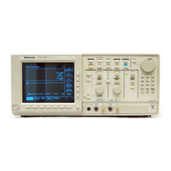
Instructions in Section 3 of this manual. These instructions will acquaint you with the use of the front-panel controls and the menu system. If you are not familiar with operating this oscilloscope, read At a Glance in Section 2 of the TDS 820 User Manual . TDS 820 Performance Verification... -
Page 16: Conventions
Brief Procedures Appendix C: Performance Verification Throughout these procedures the following conventions apply: Conventions Tighten all SMA connectors to 8.5 inch pounds (0.96 N · m). Each test procedure uses the following general format: Title of Test Equipment Required Prerequisites Procedure Each procedure consists of as many steps, substeps, and subparts as required to do the test. -
Page 17: Self Tests
No test equipment or hookups are required. Verify Internal Adjustment, Self Compensation, and Diagnostics Equipment Required: None. Prerequisites: Power up the digitizing oscilloscope and allow a 20 minute warm-up before doing this procedure. TDS 820 Performance Verification... - Page 18 Brief Procedures Procedure: Appendix C: Performance Verification 1. Verify that internal diagnostics pass: Do the following substeps to verify passing of internal diagnostics. a. Display the System diagnostics menu: Press SHIFT; then press UTILITY. Repeatedly press the main-menu button System until Diag/Err is highlighted in the pop-up menu.
-
Page 19: Functional Tests
(its label will be highlighted). If this is the case, it is not necessary to press the button. Verify All Input Channels Equipment Required: Three SMA cables and a T connector. Prerequisites: None. Procedure: 1. Install the test hookup and preset the oscilloscope controls: TDS 820 Performance Verification... - Page 20 Brief Procedures Appendix C: Performance Verification To 1 MHz TEST SIGNAL OUTPUT on Rear Panel Antistatic Grounding SMA T Wrist Strap Connector Figure 1-3: Universal Test Hookup for Functional Tests CAUTION Inputs to this oscilloscope can be damaged by static discharge. Wear your antistatic wrist strap whenever making connections the oscilloscope.
- Page 21 Test all channels: Repeat substeps a through d until all input channels are verified. 3. Remove the test hookup: Disconnect the SMA cables and T connector from the front panel inputs and the 1 MHz TEST SIGNAL OUTPUT connector. TDS 820 Performance Verification...
-
Page 22: Verify The Time Base
Brief Procedures Verify the Time Base Appendix C: Performance Verification Equipment Required: Three SMA cables and a T connector. Prerequisites: None. Procedure: CAUTION Inputs to this oscilloscope can be damaged by static discharge. Wear your antistatic wrist strap whenever making connections the oscilloscope. -
Page 23: Verify The Trigger System
2. Verify that the trigger system operates: Confirm that the following state- ments are true. The trigger level readout for the trigger system changes with the trigger LEVEL knob. The trigger-level knob can trigger and untrigger the square-wave signal as you rotate it. (Leave the signal untriggered.) TDS 820 Performance Verification... - Page 24 Brief Procedures Pressing SET LEVEL TO 50% triggers the signal that you just left Appendix C: Performance Verification untriggered. (Leave the signal triggered.) 3. Remove the test hookup: Disconnect the standard-accessory SMA cables and T connector from the front panel inputs and the 1 MHz TEST SIG- NAL OUTPUT connector.
-
Page 25: Performance Tests
—Read General Instructions and Conventions that start on page 1-1. Also, if you are not familiar with operating this Digitizing Oscilloscopes, read At a Glance in Section 3 before doing any of these procedures. 1 11 TDS 820 Performance Verification... -
Page 26: Equipment Required
Female BNC to dual banana Tektronix part number Various Accuracy Banana (two re- 103–0090–00 Tests quired) Connector, BNC Male BNC to dual female BNC Tektronix part number Checking Trigger “T” 103–0030–00 Sensitivity Coupler, Dual- Female BNC to dual male Tektronix part number... -
Page 27: Test Record
Supply bleshooting Requires a TM 500 or TM 5000 Series Power Module Mainframe. Test Record Photocopy the next three pages and use them to record the performance test results for your instrument. 1 13 TDS 820 Performance Verification... - Page 28 Performance Tests TDS 820 Test Record Instrument Serial Number: Certificate Number: Temperature: RH %: Date of Calibration: Technician: Performance Test Minimum Incoming Outgoing Maximum Net Offset Accuracy CH1 (With Delay Line) +0 V –4 mV __________ __________ +4 V +1.2 V (–) –1.2 V 2.391 V...
- Page 29 Perfromance Tests TDS 820 Test Record (Cont.) Performance Test Minimum Incoming Outgoing Maximum Rise Time (Cont.) CH2 (With Delay Line) Measured Generator Rise Rise __________ __________ 58.3 ps Time Time Option 1D (Without Delay) Measured Generator Rise Rise __________ __________ 43.8 ps...
- Page 30 Performance Tests TDS 820 Test Record (Cont.) Performance Test Minimum Incoming Outgoing Maximum Trigger Sensitivity CH1 (With Delay Line) 10 MHz 80 mV __________ __________ 200 MHz 80 mV __________ __________ 1 GHz 200 mV __________ __________ CH2 (With Delay Line)
-
Page 31: Signal Acquisition System Checks
BNC to SMA Connector Adapter Figure 1-4: Initial Test Hookup Procedure: 1. Preset the instrument controls and install the test hookup: a. Initialize the oscilloscope: Press save/recall SETUP. Press the main-menu button Recall Factory Setup. 1 17 TDS 820 Performance Verification... - Page 32 Performance Tests Press the side-menu button OK Confirm Factory Init. Press SHIFT; then UTILITY. Press the main-menu button System until Cal is highlighted in the pop-up menu. Press the main-menu button Comp All; then press the side- menu button OK Compensate All. Wait for the oscilloscope to finish the compensation.
- Page 33 (Start with the first setting listed.) Table 1-2 is for instruments with a delay line (standard instrument). Table 1-3 is for instruments without delay lines (Option 1D). Set the vertical SCALE to the setting in the table. 1 19 TDS 820 Performance Verification...
- Page 34 Performance Tests Set the generator voltage to the setting in the table. Press VERTICAL MENU. Press the main-menu button Position; and then set the vertical position to the setting in the table. Press the main-menu button Offset; and then set the offset to the setting in the table.
-
Page 35: Check Voltage Measurement Accuracy
(Item 6), one DC calibration generator (Item 14), one BNC to SMA adapter (Item 8), and two precision coaxial cables (Item 2). Prerequisites: The oscilloscope must meet the prerequisites listed on page 1-11. 1 21 TDS 820 Performance Verification... - Page 36 Performance Tests DC Calibrator Output Sense Dual Banana to BNC Adapters Coaxial Cables BNC T BNC to SMA Adapter Connector Figure 1-6: Initial Test Hookup Procedure: 1. Install the test hookup and preset the instrument controls: a. Initialize the oscilloscope: Press save/recall SETUP.
- Page 37 Vertical position is set to 0 divisions and vertical offset to 0 V when the oscilloscope is initialized in step 1. Outside the 20 C to 30 C range, calculate accuracy limits using the specification. 1 23 TDS 820 Performance Verification...
- Page 38 Performance Tests Table 1-5: Voltage Measurement at 20 _ C to 30 _ C — Without Delay Line Vertical Generator Vertical Off- Measurement Offset Accuracy Limits Scale Voltage Position set Set- Setting Setting Setting ting 100 mV 0.4 V Record measurement as V –0.4 V Record measurement as V –...
- Page 39 Set the generator output to 0 V . b. Then disconnect the cable from the generator output at the input connector of the channel last tested. Read the Mean. Figure 1-7: Measurement of Voltage Measurement Accuracy 1 25 TDS 820 Performance Verification...
-
Page 40: Check Rise Time
Performance Tests Check Rise Time Equipment Required: One calibration step generator (Item 16), and an SMA cable (Item 4). Prerequisites: See page 1-11. Procedure: 1. Preset the instrument and controls Install the test hookup: a. Initialize the oscilloscope: Press save/recall SETUP. Then press the main-menu button Recall Factory Setup. - Page 41 Low appear in the side menu (their icons are shown at the left). Press the side-menu buttons High and Low. Press the main-menu button High-Low Setup; then press the side-menu button Histogram. Read and record the high and low readouts for later use. 1 27 TDS 820 Performance Verification...
- Page 42 Performance Tests Calculate the 10% and 90% points: high 90% point high 10% point Press the main-menu button Reference Levels. Press the side-menu button High Ref; then use the keypad to enter the 90% voltage point calculated above. Press the side-menu button Low Ref; then use the keypad to enter the 10% voltage point calculated above.
-
Page 43: Check Input Resistance
BNC to dual binding post adapters (Item 7). Prerequisites: See page 1-11. Procedure: Input Sense Dual Banana to BNC Adapters Coaxial Cables BNC to SMA BNC T Connector Adapter Figure 1-10: Initial Test Hookup 1 29 TDS 820 Performance Verification... - Page 44 Performance Tests 1. Install the test hookup and preset the instrument controls: a. Install the test hookup and initialize the front panel controls: Set the DMM to measure ohms. Connect the output of the DMM through a dual-banana connector followed by a 50 precision coaxial cable to one side of a BNC T connector.
-
Page 45: Time Base System Checks
Hook up the test-signal source : Connect, through an N to BNC adapter, a coaxial cable, and a BNC to SMA adapter, the sine wave generator to 50 power divider. 1 31 TDS 820 Performance Verification... - Page 46 Performance Tests Connect one side of the power divider, through an SMA cable to the EXT TRIGGER INPUT. Connect the other side of the power divider, through an SMA male to male adapter, another power divider, and two SMA cables to the CH 1 and CH 2 inputs. Tighten SMA connectors to 8.5 inch pounds (0.96 N ·...
- Page 47 Ch 2. Press the side-menu button OK Create Math Wfm. Set the Math2 vertical scale to 10 mV. First, set the generator amplitude. Figure 1-12: Generator Settings for Delta Time Measurement Between Channels 1 33 TDS 820 Performance Verification...
- Page 48 Performance Tests 2. Confirm Delta Time Measurement Between Channels is within limits for accuracies: a. Display the test signal: Press HORIZONTAL MENU. Press the main-menu button Fine Scale. Press 75, on the key- pad; then press SHIFT. Press n, on the keypad; then press ENTER.
-
Page 49: Check Accuracy Of Single Channel Delta Time Measurements
N to BNC adapter (Item 11), one precision coaxial cable (Item 2), two SMA cables (Item 3), one 50 power divider (Item 12), and one BNC to SMA adapter (Item 8). Prerequisites: See page 1-11. 1 35 TDS 820 Performance Verification... - Page 50 Performance Tests High Frequency Sine Wave Generator Output BNC to SMA Adapter Coaxial Cable SMA Power Divider Figure 1-14: Initial Test Hookup Procedure: 1. Install the test hookup and preset the instrument controls: NOTE The two cables going to the CH 1 and EXT TRIGGER INPUT inputs must be the same length.
- Page 51 (–1.5 ns for the standard instrument and 16 ns for Option 1D). Press CLEAR MENU. CHECK that the period readout is within 984 ps to 1.016 ns (see Figure 1-15). 1 37 TDS 820 Performance Verification...
- Page 52 Performance Tests 3. Confirm measurements are within limits for accuracies at 100 ps: a. Display the test signal: Press MEASURE. Press the main-menu button Select Measurement for Chx. Press the side-menu button –more–, until Positive Cross ap- pears in the side menu. Press Positive Cross. Press HORIZONTAL MENU.
- Page 53 If your oscilloscope contains delay lines (standard instrument) adjust the general purpose knob for a +Cross readout of 3.5 ns does not have delay lines (Option 1D) adjust the general purpose knob for a +Cross readout of 20 ns cross- ing). 1 39 TDS 820 Performance Verification...
- Page 54 Performance Tests First, set the generator frequency and the +Cross; then record the +Cross and Period. Second, set the new generator frequency and the +Cross. Third, read the Period and calculate the delay. Figure 1-17: Measurement of Accuracy — Single Channel Delta Time Measurement at 10 ps Record the +Cross and Period readouts for later use.
- Page 55 Press WAVEFORM OFF. Press the front panel button that corresponds to the channel to be confirmed. 7. Disconnect the hookup: Disconnect the cables, adapters, and divider from the generator output at the input connector of the channel last confirmed. 1 41 TDS 820 Performance Verification...
-
Page 56: Trigger System Checks
Performance Tests These procedures check those characteristics that relate to the trigger system Trigger System and are listed as checked under Warranted Characteristics in Section 1, Checks Specification. Check Accuracy, Trigger-Level Equipment Required: One function generator (Item 13), one BNC to SMA adapter (Item 8), one precision coaxial cable (Item 2), 50 power divider (Item 12), and two SMA cables (Item 3). - Page 57 Press TRIGGER MENU; then press the main-menu button Level. Press the –400, SHIFT, m , and then ENTER on the keypad. Press VERTICAL MENU; then press the main-menu button offset. Press the –400, SHIFT, m , and then ENTER on the keypad. 1 43 TDS 820 Performance Verification...
- Page 58 Performance Tests First, set the generator frequency and amplitude, and set the horizontal position. Second, set the trigger level and vertical offset. Third, measure the trigger level using cursors. Figure 1-20: Measurement of Trigger-Level Accuracy Press CURSOR; then rotate the general purpose knob to align the active cursor with the start of the waveform.
-
Page 59: Sensitivity, Trigger, External, Ch 1, And Ch 2
Connect the other output of the power divider through a second SMA cable to the EXT TRIGGER INPUT. See Figure 1-21. c. Modify the initialized front-panel control settings: Set the horizontal SCALE for the M (main) time base to 200 ns. 1 45 TDS 820 Performance Verification... - Page 60 Performance Tests Press TRIGGER MENU; then press the main-menu button Mode. Now press the side-menu button Normal. Press the main-menu button Source; then press the side-menu button for the source being confirmed. Press MEASURE. Press the main-menu button High-Low Setup; then press the side-menu button Min-Max.
- Page 61 Set the horizontal SCALE for the M (main) time base to 200 ns. Set the generator amplitude so that the oscilloscope CH 1 Ampli- tude readout indicates the amplitude is 40 mV. (Readout may fluctuate around 40 mV.) 1 47 TDS 820 Performance Verification...
-
Page 62: Check Trigger Delay Jitter And Random Noise
Performance Tests b. Check for external trigger source for stable triggering at limits: Do the following in the order listed. Use the definition for a stable trigger from step 2. Press TRIGGER MENU; then press the main-menu button Source. Press the side-menu button External Trigger. Press SET LEVEL TO 50%. - Page 63 Ref 2. Press the side-menu button OK Create Math Wfm. d. Confirm that random noise is within limits: Do the following substeps. Press MEASURE. Press the main-menu button Select Measurement. 1 49 TDS 820 Performance Verification...
- Page 64 Performance Tests Press the side-menu button more until the menu label RMS appears in the side menu (its icon is shown at the left). Press the side-menu button RMS. Press CLEAR MENU. If your oscilloscope has delay lines (standard instrument), CHECK that the M2 RMS readout on screen is 1.2 mV.
- Page 65 Adjust the generator amplitude for an Pk-Pk readout of 239 mV. See Figure 1-25. Press MEASURE. Press the main-menu button Remove Measrmnt; then press the side-menu buttons Measurement 1. Press the main-menu button Select Measrmnt for CHx. 1 51 TDS 820 Performance Verification...
- Page 66 Performance Tests Press the side-menu button –more–, until Mean appears in the side menu. Press Mean. Press the side-menu button –more–, until RMS appears in the side menu. Press RMS. Third, set the generator amplitude. Figure 1-25: Trigger Delay Jitter Level Setting g.
- Page 67 Fourth, adjust the time base position to start the display at 0 V. Figure 1-26: Trigger Delay Jitter Time Base Position Fifth, measure the mean and RMS voltages. Figure 1-27: Trigger Delay Jitter Channel Noise 1 53 TDS 820 Performance Verification...
- Page 68 Performance Tests h. Calculate the channel noise: Press RUN/STOP. Read the mean and RMS voltages from the readout display. See Figure 1-27. Calculate the noise and save the result for future use: Channel noise RMS Readout in mV Mean Readout in mV Calculate the vertical noise due to jitter: Use the channel noise calcu- lated in substep h and the random noise from substep d to calculate the vertical noise due to jitter.
- Page 69 CHECK that the calculated jitter is 9 ps. 3. Test all channels: Repeat step 2 for all input channels. 4. Disconnect the hookup: Disconnect the cables, divider, attenuator, and adapter from the generator output at the oscilloscope input connectors. 1 55 TDS 820 Performance Verification...
- Page 70 Performance Tests 1 56 Performance Verification...
- Page 71 Performance Tests 1 57 TDS 820 Performance Verification...
-
Page 72: Specifications
Specifications Replace this page with the tab divider of the same name. - Page 74 Appendix B: Specification TDS 820 Performance Verification...
-
Page 75: Product Description
Oscilloscopes. Three subsections follow, one for each of three classes of traits: nominal traits, warranted characteristics, and typical characteristics . Tektronix TDS 800 Digitizing Oscilloscopes are portable, two-channel instru- General ments suitable for use in a variety of test and measurement applications and systems. - Page 76 (A math waveform results when you specify dual waveform operations, such as add, on any two channels; a reference waveform results when you save a live waveform in a reference memory.) TDS 820 Performance Verification...
-
Page 77: Horizontal System
Product Description Appendix B: Specification There are three horizontal display modes: main only, main intensified, and Horizontal System delayed only. You can select among various horizontal record length settings (see Table 2-1). Table 2-1: Record Length Versus Divisions per Record Record Length Divisions per Record (50 Points/Division) - Page 78 Digital Signal Processing (DSP) An important component of the multiprocessor architecture of this digitizing oscilloscope is Tektronix’s proprietary digital signal processor, the DSP. This dedicated processor supports advanced analysis of your waveforms when doing such compute-intensive tasks as interpolation, waveform math, and signal averaging.
- Page 79 Product Description Appendix B: Specification You may save acquired waveforms in any of four nonvolatile REF (reference) Storage and I/O memories. Any or all of the saved waveforms may be displayed for compari- son with the waveforms being currently acquired. The source and destination of waveforms to be saved may be chosen.
- Page 80 Product Description Appendix B: Specification TDS 820 Performance Verification...
- Page 81 Product Description Appendix B: Specification Specification...
-
Page 82: Nominal Traits
Input Connector Type Input Impedance nominal Ranges, Sensitivity 1 mV/div – 100 mV/div for Option 1D 2 mV/div – 200 mV/div for the delay line version of the TDS 820 Ranges, Offset, All Channels the TDS 820 Range, Position divisions The number of digitization levels (DLs) is approximately 13,100. - Page 83 External Trigger 0.5 mV increments CH 1 or CH 2 Trigger 2 mV increments (for the delay line ver- sion of the TDS 820 only) Internal Clock Out Square wave out into 50 –0.175 V to 0.100 V low level 0.850 V to 1.100 V high level...
- Page 84 0.25 1.25 (UL 198.6, 3AG): 6 A FAST, 250 V, or a 5 mm 20 mm, (IEC 127): 5 A (T), 250 V. Each fuse type requires its own fuse cap. 2 11 TDS 820 Performance Verification...
- Page 85 Forced-air circulation with no air filter Construction Material Chassis parts constructed of aluminum alloy; front panel constructed of plastic laminate; circuit boards constructed of glass-laminate. Cabi- net is aluminum and is clad in Tektronix Blue vinyl material. Finish Type Tektronix Blue vinyl-clad aluminum cabinet Weight Digitizing Oscilloscope without delay lines 13.2 kg (29 lbs), with front cover.
-
Page 86: Warranted Characteristics
2.0 V peak-to-peak for the delay line ver- sion of the TDS 820 Range, Dynamic 1 V peak-to-peak AC 2 V peak-to-peak AC for the delay line version of the TDS 820 Input Resistance for the delay line version of the TDS 820 2 13... - Page 87 0 to 50 _ C .015% (T – T ) (after user vertical compensation) at 0 to 50 _ C for the delay line version of the TDS 820 is the ambient temperature at which offset gain was adjusted. Nonlinearity, DC Integral <...
- Page 88 Accuracy = 30 ps + 0.001(10 ns + 1.5 ns) + 30 ps 0.457 = 20 + 11.5 +13.7 = 55.2 ps time intervals <500 ps measured at (time per division X the number of divisions) 500 ps. 2 15 TDS 820 Performance Verification...
- Page 89 60 mV peak-to-peak from DC to 625 MHz, linearly CH 1 and CH 2 increasing to 150 mV peak-to-peak at 1.0 GHz for the delay line version of the TDS 820 Jitter, Trigger Delay 3 ps rms + 30 parts per million (ppm) of the selected delay...
- Page 90 FCC Rules and Regulations, Part 15, Subpart J, Class A Electrostatic Discharge Up to 8 kV with no change to control settings or impairment of normal operation Up to 15 kV with no damage that prevents recovery of normal opera- tion 2 17 TDS 820 Performance Verification...
- Page 91 Warranted Characteristics Appendix B: Specification 2 18 Specification...
-
Page 92: Typical Characteristics
1.1:1 from DC to 6 GHz 1.3:1 from 6 GHz to 8 GHz 1.3:1 from DC to 6 GHz for the delay line version of the TDS 820 Crosstalk, Sine or Square Wave Input 1000:1 from DC to 8 GHz... - Page 93 Bandwidth is calculated from measured rise time using the following formula: Table 2-14: Typical Characteristics — Time Base System Name Description View Time, Pretrigger 1.5 ns for the delay line version of the TDS 820 Table 2-15: Typical Characteristics — Triggering System Name Description Pulse Width, Minimum Trigger External 0.25 ns...
- Page 94 Typical Characteristics Appendix B: Specification 2 21 TDS 820 Performance Verification...
Need help?
Do you have a question about the TDS 820 and is the answer not in the manual?
Questions and answers