Table of Contents
Advertisement
Quick Links
Advertisement
Table of Contents

Subscribe to Our Youtube Channel
Related Manuals for AMEC CUBO-160


Summary of Contents for AMEC CUBO-160
- Page 1 [ AIS Splitter ] CUBO-160...
- Page 2 The contents herein can only be used for the intended purpose of this manual. DISCLAIMER AMEC is devoted to publish and maintain this product manual. As we continue to improve our AIS products to satisfy all customers’ needs, information in this document is subject to change without notice.
- Page 3 The equipment said in this manual must only be used to which it was designed. Improper operation or installation may cause damage to the equipment or injury to personnel. AMEC will not incur any liability of equipment damage or personal injury due to improper use or installation of the equipment.
-
Page 4: About This Manual
ABOUT THIS MANUAL Congratulations on the purchase of your new CUBO-160 VHF-AIS Transponder Antenna Splitter. CUBO-160 is strictly tested to meet the rigorous demands of the marine environment. Unless improper use, installation, or maintenance, the equipment should function properly at its optimum. -
Page 5: Table Of Contents
Table of Contents COPY RIGHT & DISCLAIMER WARNING & SAFETY INSTRUCTION III. ABOUT THIS MAUNAL 1. CUBO-160 INTRODUCTION ................1 2. INSTALLATION ....................2 2.1 Items in the Package ...................... 2 2.2 Installation Procedure ..................... 3 2.2.1 Mounting ....................... 3 2.2.2 Connection Port Definition .................. -
Page 6: Cubo-160 Introduction
The CUBO-160 AIS Antenna Splitter is intelligent to arrange two active units transmitting/receiving signal with highest performance. The CUBO-160 is designed for the most power input, range from 12~24VDC. On the top panel, CUBO-160 equips with 3 LED indicators which indicate the transmitting status between VHF radio and AIS Transponder. -
Page 7: Installation
2. INSTALLATION 2.1 Items in the Package The CUBO-160 is typically delivered with standard package as shown in Table 2-1. It is also illustrated in Figure 2-1. Table 2-1 Standard equipment list Description CUBO-160 VHF Antenna Splitter main unit Manual (CD-ROM) Power Cable, 1.5m, AWG 18... -
Page 8: Installation Procedure
2.2 Installation Procedure 2.2.1 Mounting The CUBO-160 is recommended to be mounted in a dry and flat location. The location should follow the below instruction. A. Enough space for cable connection B. Keeping safe distance of 0.5m from the compass C. -
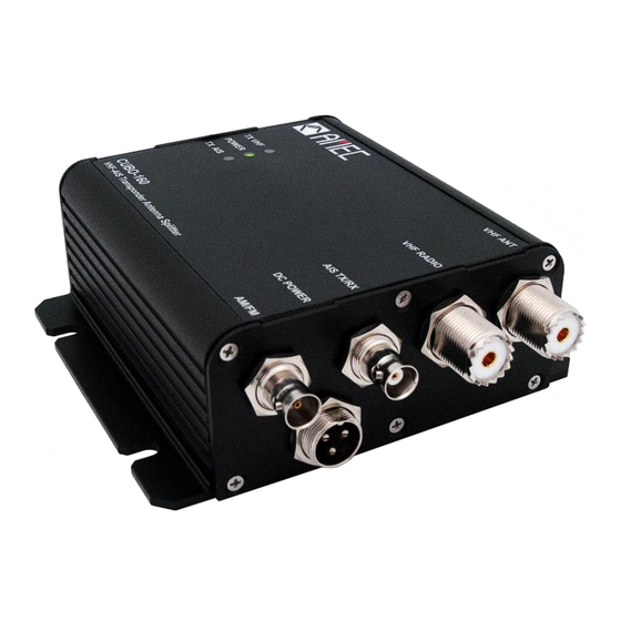
Page 9: Connection Port Definition
12~24VDC AM/FM = Connection for AM /FM Receiver Figure 2-2-2 Connection Port Definition 2.2.3 Wiring Definition in Power Cable The power cable pin definition of CUBO-160 is described as below: Table 2-2-3 External power cable pin definition Wire Color Name... -
Page 10: Connecting
2.2.4 Connecting After clarifying all definition of port on front panel, users can start install the equipments. The step of connection shows as follows. Step 1: Connect the VHF antenna to the label “VHF ANT” Connector Step 2: Connect the VHF antenna output of VHF Radio to the label “VHF Radio” Connector Step 3: Connect the VHF antenna output of AIS Transponder/Receiver to the label “AIS TX/RX”... -
Page 11: Operation
3. OPERATION 3.1 LED Indicators There are three LED Indicators on the front panel. The LED Indicators allows users to identify the status of operation after setting up all equipments. Solid green light during VHF radiotelephone transmissions Solid green light while connecting power supply Flashing green light during AIS transmissions... -
Page 12: Troubleshooting
4. TROUBLESHOOTING Step1: Check power supply switch and circuit breaker Step2: Check power supply connection and fuse “DC Power” Green LED not lighting Step3: Check power supply voltage and current Step4: Check polarity of power supply connection Step1: Check whether it is right connector port “TX VHF”... -
Page 13: Appendix
5. APPENDIX 5.1 Product Specifications RF PERFORMANCE AIS & VHF Radio Frequency Range 156.025 MHz~162.025 MHz Insertion loss, AIS Receive path Typical 4dB Insertion loss, VHF Radio Receive path Typical 4dB Insertion loss, AIS Transmit path Typical 3.5dB Insertion loss, VHF Radio Transmit path Typical 1.5dB AIS port BNC connector: Max. -
Page 14: Dimensions
5.2 Dimensions Front View Figure 5-2-1 CUBO-160 Front View Top View Figure 5-2-2 CUBO-160 Top View... - Page 15 Side View Figure 5-2-3 CUBO-160 Side View...
-
Page 16: Amec Worldwide Warranty
AMEC original equipment manufacturer (a ‘AMEC OEM’), the date that such vessel was purchased by the first retail customer. - Page 17 Costs associated with routine system checkouts, alignment/calibration, sea trials or commissioning; Defects or damage that result from the use of non-AMEC branded or certified products, accessories or other peripheral equipment, including without limitation housings, parts, or software; ...
-
Page 18: Declaration Of Conformity
No oral or written representations made by AMEC or any seller, reseller or distributor of the products, including employees and agents thereof, shall create any additional warranty obligations, increase the scope, or otherwise modify in any manner the terms of this Warranty.
Need help?
Do you have a question about the CUBO-160 and is the answer not in the manual?
Questions and answers