Table of Contents
Advertisement
Advertisement
Table of Contents

Summary of Contents for Firestone Air-rite 2581
-
Page 1: Installation Instructions
2581 riderite.com INSTALLATION INSTRUCTIONS 10-17... - Page 2 For best ride, use only enough air pressure in the Air Springs to level the vehicle when viewed from the side (front to rear). This will vary, depending on the load, location of the load, condition of the existing suspension, and personal preference. ONCE INSTALLED SUCCESSFULLY, FOLLOW THE PRESSURE REQUIREMENTS FOR THE AIR SPRINGS. FOR FIRESTONE, GENERALLY: riderite.com...
- Page 3 PARTS Compare the parts below to your kit. Assure you have all pieces, and organize them for an easier installation. MAIN KIT CONTENTS WIRELESS x 1 ECU x 1 AIR COMPRESSOR CONTROLLER AS-1 AS-1 AS-2 AS-2 IGNITION x 1 WIRE HARNESS x 1 AIR FILTER FUSE TAP AIR LINE TUBE...
- Page 4 CONTENTS AND OVERVIEW PLANNING THE PAGE INSTALL 1/8 NPT PUSH-TO-CONNECT STRAIGHT FITTING PREPARE THE AIR PAGE COMPRESSOR RED (+) AIR COMPRESSOR AIR FILTER DRILL HOLES FOR PAGE AIR COMPRESSOR AND ECU INSTALL THE PAGE AIR COMPRESSOR AND ECU BLACK (GROUND) INSTALL THE SEALED PAGE...
- Page 5 - Provides ample air flow and is protected from airborne debris and moisture. - Mount close enough to the ECU to allow Wire Harness connections to reach. - If using the optional Firestone Air Accessory Mounting Kit, consider the guidelines above, and follow the kit’s instructions.
- Page 6 PREPARE THE AIR COMPRESSOR NOTE: Air Compressor can be mounted facing any direction. Install 1/8 NPT Push-to-Connect Straight Fitting on the Check Valve. 1/8 NPT PUSH-TO-CONNECT STRAIGHT FITTING PRE-INSTALLED Tighten to engage two threads CHECK VALVE of thread lock. AIR COMPRESSOR riderite.com...
- Page 7 CHECK SURROUNDING AREA AND BACK SIDE OF MOUNTING LOCATION TO AVOID DRILLING INTO EXISTING LINES OR WIRING. IF YOU ARE USING THE OPTIONAL FIRESTONE AIR ACCESSORY MOUNTING KIT, SKIP THIS STEP AND REFER TO THE MOUNTING KIT’S INSTRUCTIONS. Drill within reach of the ground wire Using the Air Compressor ring terminal on body or frame of vehicle.
- Page 8 WIRE combine other grounds to this mounting location. BODY OR FRAME BODY OR FRAME OF VEHICLE OF VEHICLE (or optional Firestone Air Accessory mounting Air Accessory Kit cannot be used 3/16” FLAT WASHER Mounting Kit). as a grounding location for the 10-32 x 1”...
- Page 9 Route the Wire Harness in the most protected manner SEALED RELAY Drill 3/16”hole in suitable location on possible, and securely make vehicle (or use optional Firestone Air all connections as shown. Accessory Mounting Kit). 20 AMP FUSE RELAY CONNECTOR RED 12V (+)
- Page 10 INSTALL AIR LINE TUBES EXHAUST ALL AIR FROM THE SYSTEM PRIOR TO RELEASING AIR TUBES FROM AIR FITTINGS. Route the Air Line Tube from 1/8 NPT Push-to-Connect Straight Fitting on the top of the Air Compressor to the Supply (SUP) air fitting 1/8 NPT PUSH-TO-CONNECT on the ECU, leaving room STRAIGHT FITTING...
- Page 11 MORE FREQUENTLY IN DUSTY CONDITIONS. Periodically check the Air Filter during operation. When the Air Filter is dirty and needs to be replaced, contact an Authorized Firestone dealer to purchase a new one. AIR COMPRESSOR AIR FILTER Hand tighten. CLEAN UP INSTALLATION...
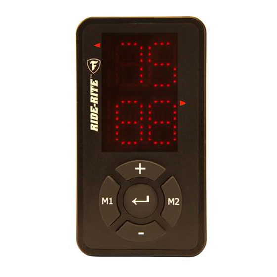
- Page 12 USING THE WIRELESS CONTROLLER Use the Wireless Controller to adjust the air pressure in your Air Springs. You can select the Air Springs individually, or both at the same time. Determine sides when in vehicle, facing forward. If desired, use the supplied Velcro Tabs to secure the remote to the vehicle.
- Page 13 FREQUENTLY ASKED QUESTIONS 1) Why is my system not powering up? 9) Is it normal for my compressor to be overworking when at- When the system does not power up, usually this is a strong indi- tempting to reach pressure? cation of improper power and grounding.
- Page 14 TEST THE SYSTEM With the Air Command F3 Kit and your Air Springs installed, you are ready to test the system. ™ Reattach the negative Use the Wireless Controller to battery cable. inflate the Air Springs to 70 PSI. See Step 8 for details. Turn on your vehicle’s ignition.
- Page 15 FIX AN AIR LEAK EXHAUST ALL AIR FROM THE SYSTEM PRIOR TO RELEASING AIR TUBES FROM AIR FITTINGS. Use the Wireless Controller to deflate the Air Springs to 5 PSI. See Step 8 for details. LEAK AT AIR LINE TUBE LEAK AT BASE OF AIR FITTING AND AIR FITTING Release Air Line Tube (see page 4).
- Page 16 Select Option 1 for Ride-Rite; Select Option 1 for Technical Support. Or, email us at rrtech@fsip.com. If emailing, please include photos to help us better diagnose and understand any problems you may be experiencing. CONNECT WITH US @rideriteair @rideriteair Firestone RideRite Firestone Ride-Rite 10-17...

Need help?
Do you have a question about the Air-rite 2581 and is the answer not in the manual?
Questions and answers