Advertisement
Quick Links
Advertisement

Summary of Contents for ECD MiniM.O.L.E.
- Page 1 MiniM.O.L.E.® rH Users Help Guide Rev 4.3.3 P/N A51-4473-16 Page 1 Rev 4.3.3...
-
Page 2: Table Of Contents
Contents Equipment ................................3 Setup ...................................7 Quick Start Guide ............................. 15 Service and Troubleshooting ........................... 21 Specifications ..............................22 P/N A51-4473-16 Page 2 Rev 4.3.3... -
Page 3: Equipment
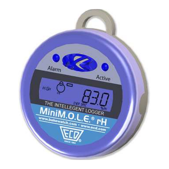
Equipment The MiniM.O.L.E.® rH provides one Relative Humidity (rH) and one Temperature channel of static data logging, suitable for Dry Cabinet, manufacturing plant ambient monitoring. With LCD Display, Magnet start, 1 second to 10 day sample rate. Features/Functions: Start Switch: This is an internal switch that is triggered when using the Start Magnet ... - Page 4 LCD Display: Provides the feature of displaying the last log reading or current reading without downloading. Refer to the table below for complete features. State: Action: LCD Display Ready Indicates Profiler Quick flashing is "Ready" to record data Start Indicates Profiler Quick flashing is starting...
- Page 5 USB Dock Station The USB Dock Station is required for the MiniM.O.L.E.® rH to communicate with the M.O.L.E.® MAP software. The USB cable connects to a computer USB Port and then the user inserts the MiniM.O.L.E.® rH into the station cradle mating the brass contacts from both units. P/N A51-4473-16 Page 5 Rev 4.3.3...
- Page 6 Start Magnet The MiniM.O.L.E.® rH Start Magnet activates the unit by triggering an internal start switch. This magnet is used only to initiate recording data after the unit is configured using the Setup Instrument wizard. To Stop recording data, the user downloads the data run by using the Read Instrument wizard or the memory limit has been reached.
-
Page 7: Setup
Setup Communications Setup Prior to operation the M.O.L.E. Profiler must be configured to properly communicate with the M.O.L.E.® MAP Software. The M.O.L.E.® MAP software must be installed prior to communications setup. (Refer to for more information). Software Installation To connect the M.O.L.E. Profiler: 1) Insert the USB computer interface cable from the Dock Station into a computer USB Port. - Page 8 2) Place the M.O.L.E. Profiler into the USB Dock Station, making sure that the two metallic contacts on the bottom of the M.O.L.E. Profiler are aligned with the contact pins on the USB Dock Station and that the M.O.L.E. Profiler is firmly seated. Typically the device drivers are already installed on Windows 7 &...
- Page 9 3) Browse to the \DriverMMrH\Installer\ folder on the M.O.L.E.® MAP Software installation CD. P/N A51-4473-16 Page 9 Rev 4.3.3...
- Page 10 4) To install the device drivers on a 32-bit operating systems, double-click VCP_Driver_Installer.exe. For 64-bit operating systems, double-click VCP_Driver_Installer_x64.exe. Depending on your operating system security settings, a Security Warning dialog box may appear. Click the Yes command button to continue. P/N A51-4473-16 Page 10 Rev 4.3.3...
- Page 11 5) “VCP Driver Installer.exe” extracts DPInst.exe and driver files into a temporary folder then starts the installation wizard. Next 6) Click the command button. P/N A51-4473-16 Page 11 Rev 4.3.3...
- Page 12 7) The wizard starts device driver installation. P/N A51-4473-16 Page 12 Rev 4.3.3...
- Page 13 When the Installation has completed, select the Finish command button. 9) Start the software program by either double-clicking the M.O.L.E.® MAP software icon or selecting it from the ECD program sub-menu. P/N A51-4473-16 Page 13 Rev 4.3.3...
- Page 14 10) On the M.O.L.E. menu, click the Select Instrument command. 11) Select the MEGARIDER™ PTP® instrument from the dialog box. If the software does not detect a M.O.L.E. Profiler, using the communication cable connect it to the computer and click the Scan for Instruments command button to search again.
-
Page 15: Quick Start Guide
Quick Start Guide This Wizard guides the user through a typical process on how to set a MiniM.O.L.E.® rH up to record data. This is available when in Engineer Mode. To set an instrument up: 1) Connect the USB Dock Station to the computer and insert the M.O.L.E. Profiler into the dock cradle. - Page 16 3) On the M.O.L.E. menu, click Setup Instrument and the workflow wizard appears. When navigating through the wizard, the step list on the left uses a color key to inform the user of the current step, steps that have been completed and remaining steps.
- Page 17 6) Set instrument name, recording interval and if the sensor is to be ON or OFF. 7) Select the Next command button to send the data listed in the dialog box to the instrument. P/N A51-4473-16 Page 17 Rev 4.3.3...
- Page 18 8) Set the assembly information such as part number, board size, sensor locations and a product image. This assembly information can then be loaded and saved from/to a an (*.XMA) file. Load: This command buttons loads an existing assembly (*.XMA). ...
- Page 19 If the user specifies a product image, clicking the Enlarge command button displays the Set Sensor Locations dialog box where the user can specify the locations of each sensor. To move sensor locations, drag the sensor markers to the approximate location where the sensors are attached.
- Page 20 10) Verify the instrument status. This dialog box displays the health of the M.O.L.E. Profiler such as battery charge, internal temperature, thermocouple temperatures. If the user selects the Show Critical command button the dialog box will only display items that will prevent the user from completing a successful data run.
-
Page 21: Service And Troubleshooting
Once it has been determined what item is causing the problem, refer to the appropriate service section. Start at the top of the list and work your way down. Here is how to contact ECD: If you still have problems, let us help you. We offer many ways to service your problems. You can call our Service/Test technicians, visit our web site to view our FAQ section (Frequently asked Questions) or send us e-mail explaining your problem in detail. -
Page 22: Specifications
Power Source The MiniM.O.L.E.® rH is powered by a 3.6 volt ½ AA lithium battery. If the LCD display is dim or does not illuminate, check the battery to see if it has become discharged. Always replace with SAFT lithium battery (LS 1425) or the equivalent specified.
Need help?
Do you have a question about the MiniM.O.L.E. and is the answer not in the manual?
Questions and answers