Table of Contents
Advertisement
Quick Links
Advertisement
Table of Contents

Related Manuals for Varytec LED Giga Bar 4 MKII


Summary of Contents for Varytec LED Giga Bar 4 MKII
- Page 1 LED Giga Bar 4 MKII LED bar user manual...
- Page 2 Musikhaus Thomann Thomann GmbH Hans-Thomann-Straße 1 96138 Burgebrach Germany Telephone: +49 (0) 9546 9223-0 E-mail: info@thomann.de Internet: www.thomann.de 03.07.2017, ID: 372989...
-
Page 3: Table Of Contents
Starting up..............................20 Connections and controls........................23 Operating..............................26 7.1 Starting the device........................... 26 7.2 Main menu............................26 7.3 Menu overview..........................31 7.4 Functions in 4-channel DMX mode................... 32 7.5 Functions in 8-channel DMX mode................... 32 LED Giga Bar 4 MKII... - Page 4 Table of contents 7.6 Functions in 12-channel DMX mode..................34 7.7 Functions in 20-channel DMX mode..................36 7.8 Functions in 32-channel DMX mode..................38 7.9 Functions in 36-channel DMX mode..................39 Technical specifications........................42 Plug and connection assignments....................43 Troubleshooting............................44 Cleaning...............................
-
Page 5: General Notes
If you sell the unit please make sure that the buyer also receives this manual. Our products are subject to a process of continuous development. Thus, they are subject to change. LED Giga Bar 4 MKII... -
Page 6: Further Information
General notes 1.1 Further information On our website (www.thomann.de) you will find lots of further information and details on the following points: Download This manual is also available as PDF file for you to download. Use the search function in the electronic version to find the topics of Keyword search interest for you quickly. -
Page 7: Notational Conventions
Texts and values displayed on the device are marked by quotation marks and italics. Examples: ‘24ch’ , ‘OFF’ . 1.3 Symbols and signal words In this section you will find an overview of the meaning of symbols and signal words that are used in this manual. LED Giga Bar 4 MKII... - Page 8 General notes Signal word Meaning DANGER! This combination of symbol and signal word indicates an immediate dangerous situation that will result in death or serious injury if it is not avoided. WARNING! This combination of symbol and signal word indicates a pos‐ sible dangerous situation that can result in death or serious injury if it is not avoided.
- Page 9 General notes Warning signs Type of danger Warning – danger zone. LED Giga Bar 4 MKII...
-
Page 10: Safety Instructions
Safety instructions Safety instructions Intended use This device is intended to be used as an electronic illumination effect using LED technics. The device is designed for professional use and is not suitable for use in households. Use the device only as described in this user manual. Any other use or use under other operating con‐ ditions is considered to be improper and may result in personal injury or property damage. - Page 11 Within the device there are areas where high voltages may be present. Never remove any covers. There are no user-serviceable parts inside. Do not use the device if covers, protectors or optical components are missing or damaged. LED Giga Bar 4 MKII...
- Page 12 Safety instructions DANGER! Electric shock caused by short-circuit Always use proper ready-made insulated mains cabling (power cord) with a pro‐ tective contact plug. Do not modify the mains cable or the plug. Failure to do so could result in electric shock/death or fire. If in doubt, seek advice from a regis‐ tered electrician.
- Page 13 Keep the device away from naked flames. NOTICE! Operating conditions This device has been designed for indoor use only. To prevent damage, never expose the device to any liquid or moisture. Avoid direct sunlight, heavy dirt, and strong vibrations. LED Giga Bar 4 MKII...
- Page 14 Safety instructions NOTICE! Power supply Before connecting the device, ensure that the input voltage (AC outlet) matches the voltage rating of the device and that the AC outlet is protected by a residual current circuit breaker. Failure to do so could result in damage to the device and possibly injure the user.
-
Page 15: Features
16 × RGBW LEDs (4-in-1, each 8 W) Strobe, dimmer and fade effect Control via DMX (6 different modes) and buttons and display on the unit three selectable automatic programmes Sound control Master / Slave mode robust metal housing LED Giga Bar 4 MKII... -
Page 16: Installation
Installation Installation Unpack and carefully check that there is no transportation damage before using the unit. Keep the equipment packaging. To fully protect the device against vibration, dust and moisture during transportation or storage use the original packaging or your own packaging material suitable for transport or storage, respectively. - Page 17 When mounting the device onto a stand, ensure that the stand is in a safe and stable position and that the weight of the device does not exceed the maximum permissible load capacity of the stand. LED Giga Bar 4 MKII...
- Page 18 Installation NOTICE! Possible data transmission errors For error-free operation make use of dedicated DMX cables and do not use ordi‐ nary microphone cables. Never connect the DMX input or output to audio devices such as mixers or ampli‐ fiers. Mounting options You can install the unit in hanging or standing position.
- Page 19 Installation Please note that this device must not be connected to a dimmer. LED Giga Bar 4 MKII...
-
Page 20: Starting Up
Starting up Starting up Create all connections while the device is off. Use the shortest possible high-quality cables for all connections. Take care when running the cables to prevent tripping hazards. LED bar... - Page 21 Connect the output of the first DMX device to the input of the second one, and so on to form a daisy chain. Always ensure that the output of the last DMX device in the daisy chain is terminated with a resistor (110 Ω, ¼ W). LED Giga Bar 4 MKII...
- Page 22 Starting up DMX indicator When the device and the DMX controller are operational, the DMX indicator in the display shows that a DMX signal is being received on the input. Connections in master/slave When you configure a group of devices in master/slave mode, the first unit will control the mode other units for an automatic, sound-activated, synchronized show.
-
Page 23: Connections And Controls
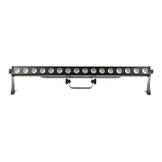
Connections and controls Connections and controls LED Giga Bar 4 MKII... - Page 24 Connections and controls 1 Lateral adjustable mounting brackets. 2 Middle adjustable mounting bracket. 3 Safety cable eyelet 4 [POWER INPUT] IEC chassis plug for mains connection. 5 [SENSITIVITY] Rotary control for setting the microphone sensitivity. 6 Microphone 7 Display [MENU/ESC] Activates the main menu and toggles between menu items.
- Page 25 Connections and controls [DOWN] Navigates downwards in a menu list. Decreases the displayed value by one. [ENTER] Selects an option of the respective operating mode. 8 [DMX OUT] DMX output. 9 [DMX IN] DMX input. LED Giga Bar 4 MKII...
-
Page 26: Operating
Operating Operating 7.1 Starting the device Connect the device to the power supply to start operation. 7.2 Main menu Press [MENU/ESC] to open the main menu. Use [UP] and [DOWN] to navigate the available sub‐ menus in the main menu. To open the highlighted submenu, press again [MENU/ESC]. LED bar... - Page 27 DMX address for the various DMX modes. Mode Highest possible DMX address 4-channel 8-channel 12-channel 20-channel 32-channel 36-channel Press [MENU/ESC] to apply the changes and to return to the main menu. LED Giga Bar 4 MKII...
- Page 28 Operating Operating mode Automatic Automatic operation can only be activated when the unit is operating in stand alone mode or as master in a master / slave combination. This setting is only relevant if the device is not con‐ trolled via DMX. Press [MENU/ESC] and use [UP] and [DOWN] to highlight the option ‘AUTO’...
- Page 29 Use [UP] and [DOWN] to select the desired mode ( ‘SoU1’ … ‘SoU3’ ). Press [MENU/ESC] to apply the changes and to return to the main menu. The microphone sensitivity is adjusted via the rotary control on the device. LED Giga Bar 4 MKII...
- Page 30 Operating Operating mode Slave This setting is only relevant if the device is working as Slave in a Master / Slave configuration and is not controlled via DMX. Press [MENU/ESC] and use [UP] and [DOWN] to highlight the option ‘SLAV’ in the main menu. Confirm with [MENU/ESC].
-
Page 31: Menu Overview
Operating 7.3 Menu overview LED Giga Bar 4 MKII... -
Page 32: Functions In 4-Channel Dmx Mode
Operating 7.4 Functions in 4-channel DMX mode Channel Value Function 0…255 Intensity red, all LEDs 0…255 Intensity green, all LEDs 0…255 Intensity blue, all LEDs 0…255 Intensity white, all LEDs 7.5 Functions in 8-channel DMX mode Channel Value Function 0…255 Dimmer LED function 0…7... - Page 33 Sound 3 0…255 Speed control for mode 1 … 27 0…255 Stroboscope effect, increasing speed 0…255 Intensity red, all LEDs 0…255 Intensity green, all LEDs 0…255 Intensity blue, all LEDs 0…255 Intensity white, all LEDs LED Giga Bar 4 MKII...
-
Page 34: Functions In 12-Channel Dmx Mode
Operating 7.6 Functions in 12-channel DMX mode Channel Value Function 0…255 Dimmer LED function 0…7 Dimmer 8…15 Strobe effect 16…23 Mode 1 … … 224…231 Mode 27 232…239 Sound 1 240…247 Sound 2 248…255 Sound 3 0…255 Speed control for mode 1 … 27 LED bar... - Page 35 Intensity blue, LED group 1 0…255 Intensity white, LED group 1 0…255 Intensity red, LED group 2 0…255 Intensity green, LED group 2 0…255 Intensity blue, LED group 2 0…255 Intensity white, LED group 2 LED Giga Bar 4 MKII...
-
Page 36: Functions In 20-Channel Dmx Mode
Operating 7.7 Functions in 20-channel DMX mode Channel Value Function 0…255 Dimmer LED function 0…7 Dimmer 8…15 Strobe effect 16…23 Mode 1 … … 224…231 Mode 27 232…239 Sound 1 240…247 Sound 2 248…255 Sound 3 0…255 Speed control for mode 1 … 27 LED bar... - Page 37 Intensity blue, LED group 2 0…255 Intensity white, LED group 2 0…255 Intensity red, LED group 3 0…255 Intensity green, LED group 3 0…255 Intensity blue, LED group 3 0…255 Intensity white, LED group 3 LED Giga Bar 4 MKII...
-
Page 38: Functions In 32-Channel Dmx Mode
Operating Channel Value Function 0…255 Intensity red, LED group 4 0…255 Intensity green, LED group 4 0…255 Intensity blue, LED group 4 0…255 Intensity white, LED group 4 7.8 Functions in 32-channel DMX mode Channel Value Function 0…255 Intensity red, LED group 1 0…255 Intensity green, LED group 1 0…255... -
Page 39: Functions In 36-Channel Dmx Mode
Intensity red, LED group 8 0…255 Intensity green, LED group 8 0…255 Intensity blue, LED group 8 0…255 Intensity white, LED group 8 7.9 Functions in 36-channel DMX mode Channel Value Function 0…255 Dimmer LED function 0…7 Dimmer LED Giga Bar 4 MKII... - Page 40 Operating Channel Value Function 8…15 Strobe effect 16…23 Mode 1 … … 224…231 Mode 27 232…239 Sound 1 240…247 Sound 2 248…255 Sound 3 0…255 Speed control for mode 1 … 27 0…255 Stroboscope effect, increasing speed 0…255 Intensity red, LED group 1 0…255 Intensity green, LED group 1 0…255...
- Page 41 Operating Channel Value Function … … … 0…255 Intensity red, LED group 8 0…255 Intensity green, LED group 8 0…255 Intensity blue, LED group 8 0…255 Intensity white, LED group 8 LED Giga Bar 4 MKII...
-
Page 42: Technical Specifications
Technical specifications Technical specifications LEDs 16 × RGBW LEDs (4-in-1, each 8 W) Beam angle 25° Number of DMX channels 4, 8, 12, 20, 32 or 36 Power consumption 90 W Operating supply voltage AC 100 – 240 V 50/60 Hz Fuse 5 mm ×... -
Page 43: Plug And Connection Assignments
The unit offers a 3-pin XLR socket for DMX output and a 3-pin XLR plug for DMX input. Please refer to the drawing and table below for the pin assignment of a suitable XLR plug. Configuration Ground, shielding Signal inverted (DMX–, ‘cold signal’) Signal (DMX+, ‘hot signal’) LED Giga Bar 4 MKII... -
Page 44: Troubleshooting
Troubleshooting Troubleshooting NOTICE! Possible data transmission errors For error-free operation make use of dedicated DMX cables and do not use ordi‐ nary microphone cables. Never connect the DMX input or output to audio devices such as mixers or ampli‐ fiers. In the following we list a few common problems that may occur during operation. - Page 45 DMX interface circuit. If the procedures recommended above do not succeed, please contact our Service Center. You can find the contact information at www.thomann.de. LED Giga Bar 4 MKII...
-
Page 46: Cleaning
Cleaning Cleaning Optical lenses Clean the optical lenses, that are accessible from the outside, regularly in order to optimize the light output. The frequency of cleaning depends on the operating environment: wet, smoky or particularly dirty surroundings can cause more accumulation of dirt on the optics of the device. -
Page 47: Protecting The Environment
Dispose of this device through an approved waste disposal firm or through your local waste facility. When discarding the device, comply with the rules and regulations that apply in your country. If in doubt, consult your local waste disposal facility. LED Giga Bar 4 MKII... - Page 48 Notes LED bar...
- Page 49 Notes LED Giga Bar 4 MKII...
- Page 50 Notes LED bar...
- Page 52 Musikhaus Thomann · Hans-Thomann-Straße 1 · 96138 Burgebrach · Germany · www.thomann.de...
Need help?
Do you have a question about the LED Giga Bar 4 MKII and is the answer not in the manual?
Questions and answers