
Subscribe to Our Youtube Channel
Related Manuals for Eclipse VeriFlame 5600


Summary of Contents for Eclipse VeriFlame 5600
- Page 1 Instruction Manual 818 2/02 VeriFlame Single Burner Monitoring System Model 5600 Version 1.21 Modulation Model No Purge Model Purge Model...
-
Page 2: About This Manual
ARRANTY limited to the furnishing of burner monitoring system replacement parts and Eclipse Combustion will not be liable for any other injury, loss, damage or expenses, whether direct or consequential, including but not limited to loss of use, income of, or damage to material arising in connection with the sale, installation, use of, inability to use or the repair or replacement of Eclipse Combustion’s products. - Page 3 Eclipse Combustion, Inc. If you do not understand any part of the information in this manual, do not continue. Contact your Eclipse sales office or Eclipse Combustion, Inc., Rock- ford, Illinois. There are several special symbols in this document. You must know their meaning OCUMENT and importance.
-
Page 4: Table Of Contents
Interrupted or Intermittent Pilot ..............Post Purge ......................Spark, Pilot Flame & Main Flame Separation ..........System Error & Lockout Conditions ............High to Low Fire Purge Modulation Capability with High to Low Fire Position Switch Interlocks ..............Eclipse Veri-Flame Instruction Manual 818 -2/02... - Page 5 Scanner Sighting Considerations ............... Test Procedures ................... Introduction ......................Flame Signal Strength ................... Minimum Pilot Test ....................Pilot Flame Failure Test ..................Main Flame Failure Test ..................Spark Sighting Test ....................Limits & Interlock Tests ..................Eclipse Veri-Flame Instruction Manual 818 -2/02...
- Page 6 LED Status & Conditions for Modulation Models (Table 8.3) ....Remote Display Messages ..............Introduction ......................Veri-Flame Operating Sequence (Table 9.1) ........... Remote Display Diagnostic Messages (Table 9.2) ......... Appendix ......................Conversion Factors ....................Illustrated Parts List ....................Eclipse Veri-Flame Instruction Manual 818 -2/02...
-
Page 7: Introduction
Introduction The Eclipse Combustion Veri-Flame Single Burner Monitoring System controls RODUCT the start-up sequence and monitors the flame of single gas, oil, or combination ESCRIPTION gas/oil burners. There are three different models to the Veri-Flame line: the no purge, the purge and the modulation models. Each model features field select- able trial for ignition (TFI). -
Page 8: Specifications
Valves, Ignition 3, 4, 5, 5 amps (maximum total connected Motors or Contactor 16 amps load not to exceed 15 amps) Alarm 5 amps 10, 11, 12, 13 5 amps Control (continued onto next page) Eclipse Veri-Flame Instruction Manual 818 -2/02... -
Page 9: Dimensions
5.5mm (7/32") Dia. Mounting 127mm 127mm Holes (4) (5") (5") Square Square Knockouts (10) for 13mm (1/2" Conduit 19mm 38mm 102mm 13mm 102mm (3/4") (1-1/2") (4") Square (1/2") (4") Square 124mm 38mm (4-7/8") (1-1/2") Eclipse Veri-Flame Instruction Manual 818 -2/02... - Page 10 (3-1/8") Remote Display Model Number 5602-DBP 89mm 102mm (3-1/2") (4") Square 54mm Square (2-1/8") Ground Screw Mounting Contrast Bracket & Adjustment Screw (2) Screw Wiring 15-pin Port Terminals (2) Terminal = Alternate Mounting Locations Eclipse Veri-Flame Instruction Manual 818 -2/02...
-
Page 11: Dip Switch Selection
Off =5 seconds. For 5605 units: On =10 seconds; Off =15 seconds). SW4 through 7: Purge time selection. Total purge time is the sum of each switch selected. SW8: Post purge selection. (On=15 second post purge). Eclipse Veri-Flame Instruction Manual 818 -2/02... -
Page 12: Modulation & Purge Dip Switch Settings
Figure 3.1 DIP Switch Location Close-up of DIP switches on back side of all Veri-Flame models. Figure 3.2 DIP Switch Labels with Selections No Purge Models Modulation Models Purge Models Eclipse Veri-Flame Instruction Manual 818 -2/02... -
Page 13: Function Summary
Low Fire Start For modulation models: when wired, the system checks for the low fire start position prior to light-off. Eclipse Veri-Flame Instruction Manual 818 -2/02... -
Page 14: High Fire/High Fire Purge Check
2) Welded internal contacts or other malfunctions in the Veri-Flame (for all models). 3) Main fuel valve (for all models)–open after cycle shutdown or before start-up. The system error light blinks twice and then remains on. The fan output terminal 8 will energize. Eclipse Veri-Flame Instruction Manual 818 -2/02... -
Page 15: High To Low Fire Purge Modulation Capability With High To Low Fire Position Switch Interlocks
Terminal 11 (Auto) Alarm and Lockout Terminal 10 (Common) Terminal 12 (Low Fire) The Automatic step occurs when the burners are operating and allows the burner firing rate to be controlled by an automatic temperature controller. Eclipse Veri-Flame Instruction Manual 818 -2/02... -
Page 16: Optional Features
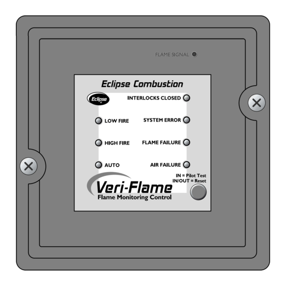
For all models: this push-button is used to activate the pilot test mode or to Test/Reset reset the Veri-Flame unit. For all models: this red LED is located behind the signal test port and illumi- Flame Signal nates when a flame signal is present. Eclipse Veri-Flame Instruction Manual 818 -2/02... -
Page 17: System Installation
Connecting the air switch in this man- ner will satisfy the open contact (air short) check on the switch. Eclipse Veri-Flame Instruction Manual 818 -2/02... -
Page 18: Ignition Wiring
1 of the Veri-Flame. Use the appropri- ate cable (Eclipse part #20318) to connect to the test jack and to the S2 termi- nal of the Veri-Flame wiring base. Do not attempt to parallel the test jack signal to other devices when using a remote display. -
Page 19: Purge And No Purge Wiring Diagram (Figure 5.1)
& Limits Alarm Proof of High Purge Flame Closure Damper Sensor Switch Terminals Common See the “High to Automatic Low Fire Purge Modulation Low Fire Capability” section on page 16 for High Fire contact connections. Eclipse Veri-Flame Instruction Manual 818 -2/02... -
Page 20: Typical Connections For All Models (Figure 5.3)
“Flame Signal” with negative point being the ground. 5. Purge time, TFI, intermittent/interrupted pilot, and recycle/non-recycle selections are made with a DIP switch located on the rear plate of the control unit. 6. Neutral must be grounded. Eclipse Veri-Flame Instruction Manual 818 -2/02... - Page 21 Internal Diagram Model Number 5602-40 Modulation Model Alarm Pilot P3 Fault Main Supervisor Jack Jumper Flame Signal Amplifier Auto 1 2 3 4 5 6 7 8 A D S2 S1 11 12 13 High Eclipse Veri-Flame Instruction Manual 818 -2/02...
- Page 22 Modulation Terminals 10 to 11 Automatic Main Flame Firing Cycle Post Trial Check Purge Recycle 10 Sec 5 Sec 15 Sec Permitted High Fire Pilot Low Fire 20 Seconds Purge Trial Purge 35 Seconds Eclipse Veri-Flame Instruction Manual 818 -2/02...
-
Page 23: Sensor Installation
“cross talk”, so the shield or flexible armor must be grounded to prevent this situation. For flame rod sensor runs approximately 100 feet (30 meters) or greater, use Eclipse part number 21741 coax cable. To achieve the maximum wiring distance, the shield should not be grounded (keep in mind that an ungrounded shield provides less protection against electrical interference). -
Page 24: Scanners
Warning Scanners Use only Eclipse scanner models as listed in the Illustrated Parts List at the end of this document. When installing scanners, please consider the following: 1) Position the scanner within 457 mm (18") of the flame. Consult factory for longer distances. -
Page 25: Test Procedures
Realign the sensor so that it requires a larger pilot flame. Repeat steps 1 through 6 until the main burner lights off smoothly and reliably. Eclipse Veri-Flame Instruction Manual 818 -2/02... -
Page 26: Pilot Flame Failure Test
Always replace faulty equipment with new equipment before resuming operation. Operating a system with de- fective safety equipment can cause explosions, injuries, and property damage. * Indicated by the illuminated red “Flame Failure” LED on the Veri-Flame front cover. Eclipse Veri-Flame Instruction Manual 818 -2/02... -
Page 27: Maintenance & Troubleshooting
4. Make sure that the following components are not damaged or distorted: • the burner nozzle • the spark plugs • the flame sensors • the flame tube or combustion block of the burner Eclipse Veri-Flame Instruction Manual 818 -2/02... -
Page 28: Troubleshooting
Electrical interference from other Check Note information on page 24 current carrying wires. regarding sensor wiring. Voltage reading greater than Check grounding of neutral at control Improper grounding. 15VDC at “Test Point” on power transformer. Veri-Flame faceplate. Eclipse Veri-Flame Instruction Manual 818 -2/02... -
Page 29: Led Status
3) Main flame fails within 35 seconds of TFI. 4) Flame failed during operation in non-recycle mode. 5) Flame failed 35 seconds after TFI and was not established after try in recycle mode. No Purge Model Eclipse Veri-Flame Instruction Manual 818 -2/02... -
Page 30: Led Status & Conditions For Purge Models (Table 8.2)
5) Flame failed 35 seconds after TFI and was not established after one try in recycle mode. AIR FAILURE 1) Air flow switch not closed within ten seconds of start-up. 2) Air flow switch is open during timing cycle. 3) Air flow switch is open during firing cycle. Purge Model Eclipse Veri-Flame Instruction Manual 818 -2/02... -
Page 31: Led Status & Conditions For Modulation Models (Table 8.3)
1) Burner in run mode, firing rate determined by automatic controller (normal operation). INTERLOCKS CLOSED and AUTO INTERLOCKS CLOSED 1) Purge high sequence (normal operation). and HIGH FIRE INTERLOCKS CLOSED and 1) Purge low sequence (normal operation). LOW FIRE Modulation Model Eclipse Veri-Flame Instruction Manual 818 -2/02... -
Page 32: Remote Display Messages
Veri-Flame and how the progress (or halt) of the sequence can be monitored by the messages on the remote display. • The second table alphabetically lists and explains the diagnostic messages which can appear on the remote display. Eclipse Veri-Flame Instruction Manual 818 -2/02... -
Page 33: Veri-Flame Operating Sequence (Table 9.1)
Holds until answer is yes. NORMAL MESSAGE FAN ENERGIZED Fan output is energized; modu- lator is sent to low fire. BURNER START-UP (see next page) * Applies to purge and no purge models only. Eclipse Veri-Flame Instruction Manual 818 -2/02... - Page 34 Spark turns off at end of TFI; sequence delayed 5 seconds. Is main flame signal present? NORMAL MESSAGE ERROR MESSAGE MAIN FLAME ON MAIN FLAME FAIL XX:XX:XX LOCKOUT Is flame signal present? (see next page) Eclipse Veri-Flame Instruction Manual 818 -2/02...
- Page 35 ERROR MESSAGE than 35 seconds? MAIN FLAME FAIL MAIN FLAME FAIL XX:XX:XX LOCKOUT RECYCLING Unit returns to beginning sequence. ERROR MESSAGE ERROR MESSAGE AIR FAILURE AIR FAILURE XX:XX:XX LOCKOUT RECYCLING Unit returns to beginning sequence. Eclipse Veri-Flame Instruction Manual 818 -2/02...
- Page 36 ERROR MESSAGE #2 – 30 SECONDS AFTER #1 UNSAFE AIR SHORT XX:XX:XX LOCKOUT ERROR MESSAGE #2 – 30 SECONDS AFTER #1 Alarm energized. UNSAFE FLAME ON XX:XX:XX LOCKOUT Alarm energized. * Applies to purge and no purge models only. Eclipse Veri-Flame Instruction Manual 818 -2/02...
-
Page 37: Remote Display Diagnostic Messages (Table 9.2)
Main flame was not established during the main burner trial for XX:XX:XX LOCKOUT ignition. MAIN FLAME FAIL Status Main flame lost during automatic modulation; control will recycle RECYCLING once if “recycle” has been selected. Eclipse Veri-Flame Instruction Manual 818 -2/02... - Page 38 UNSAFE AIR SHORT Lockout For purge & modulation models: Same conditions as above, XX:XX:XX LOCKOUT except the interlocks close before the switch reopens, causing a lockout and the alarm being energized. Eclipse Veri-Flame Instruction Manual 818 -2/02...
- Page 39 Internal control failure; replace controller. XX:XX:XX LOCKOUT WATCHDOG FAIL Lockout Internal control failure; replace controller. XX:XX:XX LOCKOUT XXXXXXX Status In combination with other messages, shows the control is in the XXXXXTESTXX minimum pilot test mode. Eclipse Veri-Flame Instruction Manual 818 -2/02...
-
Page 40: Appendix
Fahrenheit (°F) degrees Celsius (°C) foot (ft) meter (m) 0.3048 inches (in) millimeter (mm) 25.4 inches water column ("wc) millibar (mbar) 2.49 pound (lb) kilogram (kg) 0.454 pounds/sq in (psi) millibar (mbar) 68.95 Eclipse Veri-Flame Instruction Manual 818 -2/02... -
Page 41: Illustrated Parts List
LLUSTRATED ARTS Pos. Model Part Description Number Number Category Straight U.V. scanner 5600-91 49600-91 NEMA 4 U.V. scanner 5600-91N4 20898 90˚ U.V. scanner 5600-90A 49600-90 I.R. scanner 5600-92B 49600-92 Self-check scanner 5602-91 49602-91 Solid-state U.V./I.R. scanner 5600-92SC 21349 10-foot cable for self-check scanner 5602-91-7 49602-91-7 Scanner support (max. - Page 42 Offered By: Power Equipment Company 2011 Williamsburg Road Richmond, Virginia 23231 Phone (804) 236-3800 (804) 236-3882 www.peconet.com...
Need help?
Do you have a question about the VeriFlame 5600 and is the answer not in the manual?
Questions and answers
My system is running only heat is not ramping up