
Subscribe to Our Youtube Channel
Related Manuals for IMST iM871A


Summary of Contents for IMST iM871A
- Page 1 Wireless M-Bus User Manual Document ID: 4100/6404/0048 IMST GmbH Carl-Friedrich-Gauß-Str. 2-4 47475 KAMP-LINTFORT GERMANY...
-
Page 2: Revision History
C-Mode added Aim of this Document This document is intended to provide help using the iM871A Wireless M-Bus module. It gives an overview about its features and the Wireless M-Bus Stack. It explains how to control the module by a connected host controller. -
Page 3: Table Of Contents
User Manual iM871A Wireless M-Bus Table of Contents Table of Contents 1. G ENERAL 1.1 Key Features 1.2 Applications 2. G ENERAL EATURE VERVIEW 3. M ODULE IRMWARE 3.1 Wireless M-Bus Stack 3.1.1 General 3.1.2 WM-Bus Modes 3.1.3 WM-Bus Telegrams 3.2 Serial Interface... - Page 4 User Manual iM871A Wireless M-Bus Table of Contents 5.1.2 USB Interface 5.2 USB-Stick 5.2.1 USB Driver 5.3 Configuration with WM-Bus Studio 6. O RDERING INFORMATION 7. A PPENDIX 7.1 List of Abbreviations 7.2 List of Figures 7.3 List of Tables 7.4 References...
-
Page 5: General
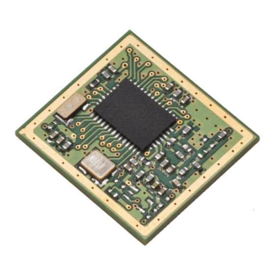
(S1, S1-m, S2, T1, T2, R2, C1 and C2). With a standby current of less than 1 µA, the iM871A is well suited for battery powered devices like water and gas meters. The pre-certified module provides a serial interface as well as analog and digital inputs and outputs and can easily be integrated into a meter. -
Page 6: Applications
User Manual iM871A Wireless M-Bus General Applications The iM871A wireless M-Bus module offers a cost-effective RF solution for smart metering applications connecting water, heat, electricity and gas meters with data concentrators in the 868 MHz frequency band. Electricity meters Gas, water and heat meters... -
Page 7: General Feature Overview
General Feature Overview General Feature Overview The iM871A Wireless M-Bus module offers lots of features which gives the user the possibility to save implementing functionalities on the host controller side. With the PC Application Wireless M-Bus Studio the features can easily be explored. The module can either be used as WM-Bus modem or can be taken as stand-alone solution (on request). - Page 8 Features Host Controller Interface With a message based serial protocol the user is able to connect the iM871A radio module to a host system. It can be used for configuration, data exchange and device control. Each message to or from the radio module is embedded in a specific message frame. For Windows PC applications a library (DLL) can be used.
- Page 9 The Message Generator offers the possibility to simulate real Wireless M-Bus packets. The format is conform to the EN13757-4 standard. The content of these packets can be changed. With this function the users is able to test the iM871A radio module against other Wireless M- Bus devices.
-
Page 10: Module Firmware
Figure 3-1: iM871A WM-Bus Stack 3.1.1 General The Wireless M-Bus protocol stack implemented on iM871A is compliant the European standard 13757 part 4: "Communication systems for meters and remote reading of meters" [1]. It describes the wireless communication of water, heat, electricity and gas meters with data concentrators. -
Page 11: Wm-Bus Modes
Module Firmware 3.1.2 WM-Bus Modes The iM871A supports all link modes according to EN 13757-4: S (stationary), T (frequent transmit), R (frequent receive) and C (compact operation). These four main modes are divided into further sub-modes for dedicated applications. All modes are described from the meters view. - Page 12 Receiving (meter) at 869,525 MHz, chip rate: 50 kcps, decoding: "NRZ" Telegram Format A / Telegram Format B Note: The iM871A can be used as RF-Adapter for Wireless M-Bus devices. It provides the physical access to the Wireless M-Bus "Network". For complete Wireless M-Bus protocol operation a host controller is needed which is able to generate telegrams which meet the EN13757-3 requirements.
-
Page 13: Wm-Bus Telegrams
User Manual iM871A Wireless M-Bus Module Firmware 3.1.3 WM-Bus Telegrams In this section the message format on the air interface is described. There are two different telegram formats specified in EN13757-4. Telegram Format A and Telegram Format B. The operating modes S, T and R2 use Telegram Format A. The C-mode supports both telegram formats. - Page 14 User Manual iM871A Wireless M-Bus Module Firmware Block 3 to block n (optional blocks): Data-Field CRC-Field 16 bytes or, if last block, ((L-9) MOD 16) bytes 2 bytes Figure 3-5: Wireless M-Bus Telegram Format A, block3 to block n Wireless M-Bus Telegram Format B...
-
Page 15: Serial Interface
With this message based serial protocol the user is able to connect the iM871A radio module to a host system. It can be used for configuration, data exchange and device control. Each message to or from the radio module is embedded in a specific message frame. -
Page 16: Device Configuration
User Manual iM871A Wireless M-Bus Module Firmware Get Device Info For identification purpose the WM-Bus firmware provides a service to readout some information elements e.g. Module Type, Firmware Version. This command returns the basic device information block. 3.2.4 Device Configuration The WM-Bus Firmware supports several kinds of configurable system parameters which can be stored in a non-volatile parameter memory. -
Page 17: Operation Modes
Application Mode Hardware Test Mode 3.2.6 Real Time Clock Support The iM871A provides an embedded RTC which can be used for timer controlled operations e.g. automatic transmission of WM-Bus messages at specific times or with a configurable interval. Get RTC Time This function can be used to read the RTC time. -
Page 18: Aes-128 Encryption / Decryption
RX Indicator (module pin 6) toggles every time a message was received When using the iM871A in Wireless M-Bus Starter-Kit the indicator pins are connected to LEDs of the Demo Board. iM871A_WMBus_UserManual.docx, Wireless Solutions, v1.2... -
Page 19: Module Specification
Module Specification Module Specification General Radio Settings In this chapter the possible radio configurations of the iM871A are described. 4.1.1 Channel Setup Table 4-1 shows the RF channel setup. These channels are available in R-Mode for transmissions from Meter to Other devices. The opposite direction is always done in 868.33 MHz (channel 5). -
Page 20: Data Rate Setup
User Manual iM871A Wireless M-Bus Module Specification 4.1.3 Data Rate Setup Table 4-3 shows the used RF data rates setups. They are configured automatically by the module firmware dependent on the selected Wireless M-Bus mode, the Device Mode and the data direction. - Page 21 User Manual iM871A Wireless M-Bus Module Specification Figure 4-2 shows the time gap between the RX signal and the wake-up indication. Figure 4-2: Packet Timing after Wake-up, detailed view iM871A_WMBus_UserManual.docx, Wireless Solutions, v1.2 Page 20...
-
Page 22: Current Consumption
User Manual iM871A Wireless M-Bus Module Specification Current Consumption Figure 4-3 shows schematically the current consumption of a meter device, that is triggered by the host controller to transmit a Wireless M-Bus packet every 2 seconds. After transmission the meter is able to receive commands from a master device (concentrator, data collector, etc.). -
Page 23: Wireless M-Bus Starter-Kit
Figure 5-1 gives an overview of the Demo Board and its peripherals. Figure 5-1: Demo Board Using the Demo Board with the iM871A it must be soldered on its specific adapter board and plugged into X1 and X2. Now all necessary module pins are available on X5, X6, and X7 of the Demo Board. -
Page 24: Power Supply
In position “USB” the USB bus voltage together with a voltage regulator (3 V) is used. In position “BAT” the battery voltage is used directly. LED 6 is turned on when the iM871A is powered on. Additionally LED 5 is turned on if a USB connection to a PC is established. It is recommended either to use the battery or the USB power, thus S1 can be used as on-off- switch. -
Page 25: Usb-Stick
Wireless M-Bus Studio as well. With its internal antenna nothing more is needed as a free USB port on the host system. The iM871A USB-Stick is not part of the Wireless M-Bus Starter-Kit, it has to be ordered separately. -
Page 26: Configuration With Wm-Bus Studio
Configuration with WM-Bus Studio The Wireless M-Bus Studio is a Windows tool which allows to explore the capabilities of the iM871A. The GUI offers a comfortable way to configure and control some features of the embedded Wireless M-Bus Stack like: •... -
Page 27: Ordering Information
– USB USB Stick with module iM871A wimod@imst.de Notes: The Starter Kit contains two Demo Boards, two Adapter Boards with iM871A, two antennas, batteries, and a CD with documentation. Table 6-1: Ordering Information iM871A_WMBus_UserManual.docx, Wireless Solutions, v1.2 Page 26... -
Page 28: Appendix
User Manual iM871A Wireless M-Bus Appendix Appendix List of Abbreviations = Analog-to-Digital Converter = Automatic Meter Reading = Digital Input/Output = Dynamic Link Library = Graphical User Interface = Host Controller Interface = Microcontroller Unit = Printed Circuit Board = Packet Error Rate... -
Page 29: List Of Figures
Appendix List of Figures Figure 1-1: iM871A ..................... 4 Figure 2-1: iM871A Metering Application Example with Host Controller ......6 Figure 2-2: iM871A Metering Application Example Stand-Alone ........6 Figure 3-1: iM871A WM-Bus Stack ................9 Figure 3-2: Wireless M-Bus Telegram Format A ............. 12 Figure 3-3: Wireless M-Bus Telegram Format A, block1 (header) ........ -
Page 30: References
User Manual iM871A Wireless M-Bus Appendix References EN13575-4 : 2011 Communication systems for meters and remote reading of meters WM-Bus Studio User Manual iM871A HCI Specification iM871A Datasheet iM871A_WMBus_UserManual.docx, Wireless Solutions, v1.2 Page 29... -
Page 31: Regulatory Compliance Information
According to the R&TTE directive, the declaration of compliance with essential requirements of the R&TTE directive is within the responsibility of the manufacturer of the final product. A declaration of conformity for the radio module is available from IMST GmbH on request. -
Page 32: Important Notice
Important Notice Disclaimer IMST GmbH points out that all information in this document is given on an “as is” basis. No guarantee, neither explicit nor implicit is given for the correctness at the time of publication. IMST GmbH reserves all rights to make corrections, modifications, enhancements, and other changes to its products and services at any time and to discontinue any product or service without prior notice.
Need help?
Do you have a question about the iM871A and is the answer not in the manual?
Questions and answers