Table of Contents
Advertisement
Save This Manual for Future Reference
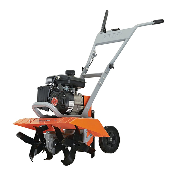
Front Tine Tiller
Operator's Manual
MODEL NUMBER
YT5328
SERIAL NUMBER
PURCHASE DATE
Both model number and serial
number may be found on the
main label (see Page 2, Figure 1).
You should record both of them
in a safe place for future use.
FOR YOUR SAFETY
READ AND UNDERSTAND THE ENTIRE MANUAL BEFORE OPERATING MACHINE
Tame the Great Outdoors
TM
Advertisement
Table of Contents

Related Manuals for YARDMAX YT5328

Summary of Contents for YARDMAX YT5328
-
Page 1: For Your Safety
Save This Manual for Future Reference Front Tine Tiller Operator’s Manual MODEL NUMBER YT5328 SERIAL NUMBER PURCHASE DATE Both model number and serial number may be found on the main label (see Page 2, Figure 1). You should record both of them in a safe place for future use. -
Page 2: Table Of Contents
Up for the job? YARDMAX is. When looking for outdoor power equipment (OPE) to get the job done right, at the right price, YARDMAX delivers the perfect combination of performance and practicality. YARDMAX has a solution that’s right for you. - Page 3 California to cause cancer and birth defects Figure 1 or other reproductive harm. DISCLAIMER YARDMAX reserves the right to discontinue, change, ENVIRONMENTAL and improve its products at any time without notice or obligation to the purchaser. The descriptions and Recycle unwanted materials instead of disposing of them as waste.
-
Page 4: Specifications
SUPPORT Have questions about your YARDMAX equipment? Call us at 844-YARDMAX, email us at support@yardmax.com, or contact us via your favorite social media site. SPECIFICATIONS Model number YT5328 Engine YARDMAX Displacement 98 cc Torque (ft-lbs, gross) 3.33 Start Type Recoil... -
Page 5: Symbols
Front Tine Tiller Operator’s Manual » Model number YT5328 Tine Diameter 11" Depth Adjustments 4 Positions Tine RPM 180 RPM Tilling Width 11" – 21" Tilling Depth 7" – 11" Dimensions (l × W × H) 48" × 24" × 40"... -
Page 6: Safety
SAFETY GENERAL SAFETY RULES UNDERSTAND YOUR MACHINE Stay alert, watch what you are doing, and use common sense when operating the machine. Read this manual and labels affixed to the machine to understand its limitations and potential hazards. Do not overreach. Do not operate the machine while barefoot or when wearing sandals or similar lightweight footwear. -
Page 7: Specific Safety Rules
Front Tine Tiller Operator’s Manual » Do not tamper with the engine in an effort to get it to run at loosen the fuel tank cap slowly to relieve any pressure in the tank. higher speeds. The maximum engine speed is preset by the Never overfill the fuel tank. -
Page 8: Contents Supplied
COnTEnTS SUPPlIED Your YARDMAX front tine tiller comes partially assembled and contains the following: HARDWARE KIT 1. Upper Handlebar M8 × 45 × 2 2. Main Machine M8 × 25 × 2 3. Outer Tine - Right M8 × 25 ×... -
Page 9: Assembly
Front Tine Tiller Operator’s Manual » ASSEMblY This front tine tiller was partially assembled at the factory. To assemble your machine follow the below instructions. INNER TINE LOWER HANDLEBAR Align the holes in the lower handlebar with the holes in the support bracket. - Page 10 HANDLEBAR ADJUSTING PLATE × 2 Align the two lower holes in each adjusting plate with the holes in the lower handlebar. Insert M8×25 bolts and screw big washer, M8 nuts tightly. (See Figure 4) Adjusting Hole Adjusting Hand Knob × 2 Bolt Hole Handlebar Adjusting Plate M8×25...
- Page 11 Front Tine Tiller Operator’s Manual » TINE SHIELD DEPTH STAKE Assemble the tine shields using six M6×16 bolts, flat washers, and Insert the depth stake into the depth stake holder tube.(See M6 lock nuts. (See Figure 6) Illustration 1, Figure 8a) Adjust the depth stake into the desired depth of tilling (See Figure 8b), then lock it with 8×32 pin and clevis pin.
-
Page 12: Know Your Machine
KnOW YOUR MACHInE FEATURES AND CONTROLS Drive Control Lever Handlebar Oil Tank Muffler Air Filter Depth Stake Transport Wheel Tine Shield Inner Tine Outer Tine Choke Control Throttle Control Recoil Starter Handle Engine ON/OFF Switch Know Your Machine YT5328PM01 - 1705... - Page 13 Front Tine Tiller Operator’s Manual » HANDLEBAR TINE SHIELD Adjustable to protect small plants from being buried. Unscrew this lever, move 3-POSITION the handle up or down. RECOIL STARTER HANDLE Fasten the lever. (See ADJUSTABLE HANDLE BARS Figure 4b) The Recoil Starter Handle is used to start the engine. THROTTLE CONTROL The throttle control regulates the speed of the engine, and moves between FAST...
-
Page 14: Operation
OPERATION ADD OIL TO ENGINE IMPORTANT: DO NOT OVERFILL! This equipment and/or its engine may include The engine is shipped without oil. Do not start the evaporative emissions control system components, engine before adding oil. Refer to your engine manual required to meet EPA and/or CARB regulations, that for the proper oil gauge to use. - Page 15 Front Tine Tiller Operator’s Manual » TILLING 4. Pull the recoil starter until the engine starts. Return the recoil to the home position after each pull. Repeat the steps as Tilling is digging in, turning over and breaking up garden soil to needed.
-
Page 16: Maintenance
MAInTEnAnCE Maintaining your YARDMAX front tine tiller will ensure long life to the machine and its components. Grease Fitting Screw PREVENTIVE MAINTENANCE Air Went Screw 1. Turn off the engine and disengage all command levers. The engine must be cool. - Page 17 Front Tine Tiller Operator’s Manual » REPLACING THE BELT Transmission Pulley 1. Remove the one bolt in the upper belt guard and four bolts in the lower belt guard to expose the belt assembly. (See Figure 13a) 2. Loosen the two stud bolts that fix both belt guide rods. (See Figure 13b, Illustration 1) 3.
-
Page 18: Storage
STORAGE If the front tine tiller will not be used for a period longer than 30 Do not use strong detergents or petroleum based days, follow the steps below to prepare your unit for storage. cleaners when cleaning plastic parts. Chemicals can 1. - Page 19 Front Tine Tiller Operator’s Manual » Problem Cause Remedy 1. Spark plug wire is loose 1. Connect and tighten spark plug wire 2. Unit running with Choke lever in 2. Move choke lever to OPEn position ClOSE position 3. Clean fuel line. Fill tank with clean, 3.
-
Page 20: Parts Diagram
PARTS DIAGRAM Parts Diagram YT5328PM01 - 1705... -
Page 21: Parts List
Front Tine Tiller Operator’s Manual » PARTS LIST Description QTY. Description QTY. Handlebar Grip bolt M10×100 Upper Handlebar bolt M8×235 Adjusting Hand Knob M8×25 bolt M6×16 Tensioning Pulley Cable Flat Washer 6 Inner Hexangular Screw M6×35 bolt M6×40 Flange lock nut M5 bolt M8×25 Drive Control lever bolt M8×20... -
Page 22: Yt5328Pm01
Description QTY. Description QTY. Transmission Case - Right Flat Key A6×28 Snap Ring 25 Worm Wheel bearing 6005-2Z(HCH) bearing 6004-2RS Worm Wheel bushing Flat Key 5×5×20 bearing 30204(HCH) big Pulley Worm Axis Transmission Case - left Worm Rod bolt M8×12 Parts List YT5328PM01 - 1705... - Page 23 Front Tine Tiller Operator’s Manual » Parts List YT5328PM01 - 1705...
- Page 24 Tame the Great Outdoors 1850 W Winchester Rd, Suite 106 Libertyville, IL 60048 844-YARDMAX info@yardmax.com (844-927-3629)
Need help?
Do you have a question about the YT5328 and is the answer not in the manual?
Questions and answers