Sign In
Upload
Download
Table of Contents
Contents
Add to my manuals
Delete from my manuals
Share
URL of this page:
HTML Link:
Bookmark this page
Add
Manual will be automatically added to "My Manuals"
Print this page
×
Bookmark added
×
Added to my manuals
Manuals
Brands
INVT Manuals
UPS
HT1101S
User manual
INVT HT1101S User Manual
Rack-online ups (1-3kva)
Hide thumbs
1
2
Table Of Contents
3
4
5
6
7
8
9
10
11
12
13
14
15
16
17
18
19
20
21
22
23
24
25
26
27
28
29
30
31
32
33
34
35
36
37
38
39
40
41
42
page
of
42
Go
/
42
Contents
Table of Contents
Troubleshooting
Bookmarks
Table of Contents
User Manual
Important Safety Instructions
Table of Contents
Contents
1 Electromagnetic Compatibility
2 Introduction
3 System Description
Transient Voltage Surge Suppression (TVSS) and EMI/FRI Filters
Rectifier/Power Factor Correction (PFC) Circuit
Inverter
Battery Charger
DC-To-DC Converter
Battery
Dynamic Bypass
4 Product Specification and Performance
Model Description
5 Installation
Unpacking and Inspection
Mechanical Installation
Notes for Installation
Tower Installation
Rack Installation
Operating Procedure for Connecting the Long Backup Time Model UPS with the External Battery
6 Controls and Indicators
Operation and Display Panel
Audible Alarm
7 Operation
Operation Mode
8 Battery Maintenance
Replacing Internal Battery Pack
9 Notes for Battery Disposal and Replacement Procedures
Battery Disposal
Battery Replacement Procedures
10 Trouble Shooting
Checking UPS Status
Adjust the Factors Caused the Problem
Annex A. Intelligent Slot
Annex B. EPO
Annex C. Rated Parameters Setting
Annex D. Battery Kit Assembly (Option)
Advertisement
Quick Links
1
User Manual
2
Operation and Display Panel
3
Operation Mode
4
Checking Ups Status
5
Trouble Shooting
Download this manual
User Manual
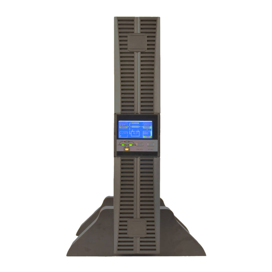
Rack-online UPS
(1-3kVA)
Table of
Contents
Previous
Page
Next
Page
1
2
3
4
5
Advertisement
Table of Contents
Need help?
Do you have a question about the HT1101S and is the answer not in the manual?
Ask a question
Questions and answers
Related Manuals for INVT HT1101S
UPS INVT HT1106S User Manual
True online 6-20k ups (39 pages)
UPS INVT HT1102S User Manual
Rack-online ups (1-3kva) (42 pages)
UPS INVT HT1103S User Manual
Rack-online ups (1-3kva) (42 pages)
UPS INVT HT33 Series User Manual
(44 pages)
UPS INVT HT33 Series Service Manual
(60 pages)
UPS INVT HT33010XS Service Manual
(60 pages)
UPS INVT RM300 Service Manual
(28 pages)
This manual is also suitable for:
Ht1101l
Ht1103l
Ht1102l
Ht1102s
Ht1103s
Ht11 series
Table of Contents
Save PDF
Print
Rename the bookmark
Delete bookmark?
Delete from my manuals?
Login
Sign In
OR
Sign in with Facebook
Sign in with Google
Upload manual
Upload from disk
Upload from URL


Need help?
Do you have a question about the HT1101S and is the answer not in the manual?
Questions and answers