INTORQ BFK458 Operating Instructions Manual
Electromagnetically-released spring-applied brake
Hide thumbs
Also See for BFK458:
- Original operating instructions (74 pages) ,
- Translation of the original operating instructions (54 pages) ,
- Manual (32 pages)

Related Manuals for INTORQ BFK458


Summary of Contents for INTORQ BFK458
- Page 1 INTORQ BFK458 Electromagnetically-released spring-applied brake Operating Instructions Phone: 800.894.0412 - Fax: 888.723.4773 - Web: www.actechdrives.com - Email: info@actechdrives.com...
- Page 2 Product key Product key INTORQ Legend for the product key INTORQ BFK458 Product group Braking Product family Spring-applied brake Type Size 06, 08, 10, 12, 14, 16, 18, 20, 25 ...
- Page 3 Amendment of drawings, Fig. 12, Fig. 13, Fig. 14, Fig. 15 and Fig. 16 New: Chapter 7.4 ”Spare parts list for double spring-operated brake” 13040626 02/2005 TD09 Change of company name to INTORQ 13284675 01/2009 TD09 Change of tightening torques Supplementation of Tab.
-
Page 4: Table Of Contents
j | BA 14.0168 | 10/2013 Contents Preface and general information ........About these Operating Instructions . - Page 5 j | BA 14.0168 | 10/2013 Contents Maintenance/repair ..........Wear of spring-applied brakes .
-
Page 6: Preface And General Information
For example: 16 = see page 16 Document reference Reference to another documentation with additional information For example: Operating instructions Wildcard Wildcard for options, selections For example: BFK458- = BFK458-10 Phone: 800.894.0412 - Fax: 888.723.4773 - Web: www.actechdrives.com - Email: info@actechdrives.com... -
Page 7: Abbreviations Used
j | BA 14.0168 | 10/2013 Preface and general information Abbreviations used Letter symbol Unit Name Current Holding current, at 20 °C and withstand voltage Release current, at 20 °C and release voltage Rated current, at 20 °C and rated voltage Tightening torque of the fixing screws Characteristic torque of the brake, characteristic value of a relative speed of 100 rpm... -
Page 8: Notes Used
j | BA 14.0168 | 10/2013 Preface and general information Notes used The following pictographs and signal words are used in this documentation to indicate dangers and important information: Safety instructions Structure of safety instructions: Danger! Characterises the type and severity of danger Note Describes the danger Possible consequences:... -
Page 9: Scope Of Supply
Manufacturer: INTORQ GmbH & Co KG, Wülmser Weg 5, D-31855 Aerzen The spring-applied INTORQ brake i s also delivered in single modules and individually combined to its modular design. The data - package labels, nameplate, and type code in particular - apply to one complete stator. -
Page 10: Legal Regulations
– operating faults – disregarding the documentation Warranty Terms of warranty: see terms of sale and delivery of INTORQ GmbH & Co. KG. Warranty claims must be made to INTORQ immediately after detecting defects or faults. The warranty is void in all cases where liability claims cannot be made. -
Page 11: Safety Instructions
This is vital for a safe and trouble-free operation and for achieving the specified product features. Only qualified, skilled personnel are permitted to work on and with INTORQ components. In accordance with IEC 60364 or CENELEC HD 384, qualified, skilled personnel are persons ... -
Page 12: Application As Directed
– ... must not be operated beyond their corresponding power limits. Any other use shall be deemed inappropriate! Possible applications of the INTORQ spring-applied brake Humidity: no restrictions – In case of formation of condensed water and moisture: provide for appropriate ventilation to ensure that all components will dry quickly. -
Page 13: Technical Data
Technical data Technical data Product description 3.1.1 Structure and function KL 14.0606/1 Fig. 1 Design of the spring-applied brake INTORQ BFK458: basic module E (complete stator) + rotor + hub + flange Complete stator Rotor Flange Compression springs Sleeve bolts... - Page 14 (1.2) by friction locking. The brake is released electromagnetically. The spring-applied brake INTORQ BFK458- is a single-disk brake with two friction surfaces. Several compression springs (1.2) create the braking torque by friction locking. The brake is released electromagnetically.
-
Page 15: Characteristics
j | BA 14.0168 | 10/2013 Technical data 3.1.7 Encapsulated design (optional) This design not only avoids the penetration of spray water and dust, but also the spreading of abrasion particles outside the brake. This is achieved by: a cover seal over the armature plate and rotor, a cover in the adjuster nut, a shaft seal in the adjuster nut for continuous shafts (option). - Page 16 j | BA 14.0168 | 10/2013 Technical data Size 80 E 1.5 E 3.5 N/E 25 N/E 35 N/E 65 N/E 115 N/E 175 N/E 2 N/E 7 N/E 14 N/E 35 N 45 N/E 80 N/E 145 N/E 2.5 N/E 5 N/E 9 N/E 18 N/E...
- Page 17 Brake torques depending on the speed and permissible limit speeds Type Rated torque at Δn = 100 Braking torque at Δn [rpm] [%] max. speed Δn with 0max. horizontal mounting position 1500 3000 maximum [rpm] BFK458-06 6000 BFK458-08 5000 BFK458-10 4000 BFK458-12 BFK458-14 IBFK458-16 3600 IBFK458-18 BFK458-20 BFK458-25 3000 Tab.
- Page 18 29.1 Tab. 4 Characteristics of INTORQ BFK458 spring-applied brake The friction lining is designed such that the brake can be adjusted at least 5 times. The screw length is dependent on the material and the thickness of the mounting surface provided by the customer.
- Page 19 Technical data Type Electrical power P Rated current I Release Coil resistance R ±8 % voltage/holding voltage [Ω] 0.83 0.21 460.8 0.194 530.5 0.114 1445 BFK458-06 0.111 1620 0.105 1805 0.098 2101 1.04 0.26 0.242 424.4 0.147 1156 BFK458-08 0.138 1296 0.131...
- Page 20 | BA 14.0168 | 10/2013 Technical data Type Electrical power P Rated current I Release Coil resistance R ±8 % voltage/holding voltage [Ω] 3.54 0.885 108.4 0.825 124.8 BFK458-18 0.472 387.2 0.447 424.7 0.414 494.4 4.16 5.76 1.04 92.2 0.970 106.1 0.588 BFK458-20 0.55...
-
Page 21: Operating Times
Rated torque at Max. permissible Transition Operating times [ms] at s Δn = 100 rpm friction work per operating and 0.7 I operation only frequency DC engagement Disengage [Nm] BFK458-06 3000 IBFK458-08 7500 BFK458-10 12000 BFK458-12 24000 BFK458-14 30000 BFK458-16 36000 BFK458-18... - Page 22 j | BA 14.0168 | 10/2013 Technical data Engagement time The transition from brake-torque free state to holding braking torque is not free of time lags. Short brake engagement times are vital for emergency braking. DC switching together with a suitable spark suppressor must therefore be provided. The engagement times are valid for DC switching with a spark suppressor.
-
Page 23: Friction Work / Operating Frequency
j | BA 14.0168 | 10/2013 Technical data Friction work / operating frequency Sizes Operating frequency S Fig. 4 Friction work as a function of the operating frequency − p −p ÜìÉ ÜìÉ N − É p Ü ëã~ñ... -
Page 24: Emission
The user must ensure compliance with EMC Directive 2004/108/EC using appropriate controls and switching devices. If an INTORQ rectifier is used for the DC switching of the spring-applied brake and if the operating frequency exceeds five switching operations per minute, the use of a mains filter is required. -
Page 25: Mechanical Installation
The form and position tolerances exclusively apply to the materials mentioned. If other materials are used, please contact INTORQ. The brake flange must be supported by the end shield across the full surface. Phone: 800.894.0412 - Fax: 888.723.4773 - Web: www.actechdrives.com - Email: info@actechdrives.com... -
Page 26: Necessary Tools
Mechanical installation Minimum requirements for end shield: Material S235 JR , C15 or EN-GJL-250 – Consult INTORQ if other materials are to be used. Evenness – Size 06 to 12: < 0.06 mm – From size 14: < 0.1 mm Axial runout 0.10 mm,... -
Page 27: Mounting
j | BA 14.0168 | 10/2013 Mechanical installation Feeler gauge Caliper gauge Multimeter Mounting 4.4.1 Preparation 1. Unpack spring-applied brake. 2. Check for completeness. 3. Check nameplate data, especially rated voltage. Installation When you have ordered a version with manual release or flange, attach these units first. 4.5.1 Installation of the hub onto the shaft ... - Page 28 j | BA 14.0168 | 10/2013 Mechanical installation K14.0502/1 Fig. 5 Mounting the hub on the shaft Circlip End shield 1. Press the hub (4) on the shaft. 2. Secure the hub against axial displacement, e.g. with a circlip (4.1). ...
- Page 29 j | BA 14.0168 | 10/2013 Mechanical installation Stop! Please note the following for the version ”brake with shaft sealing ring in torque adjustment ring”: 2. Lightly lubricate the lip of the shaft seal with grease. 3. When assembling the stator (1), push the shaft sealing ring carefully over the shaft. –...
- Page 30 j | BA 14.0168 | 10/2013 Mechanical installation KL458-012A Fig. 8 Torque setting Stator Sleeve bolt 10 Cheese head screw 1. Check the air gap near the screws (10) by means of a feeler gauge and compare the values to the values for ”s ”...
- Page 31 j | BA 14.0168 | 10/2013 Mechanical installation 4.5.3 Assembly of the friction plate, sizes 06 to 16 KL458-009-a Fig. 10 Mounting the friction plate 15 End shield 27 Friction plate 1. Put a friction plate (27) or flange (6) against the end shield (15). ...
- Page 32 j | BA 14.0168 | 10/2013 Mechanical installation KL458-008-a Fig. 11 Mounting the flange Flange End shield Set of fastening screws 1. Hold the flange (6) against the end shield (15) and check the pitch circle and retaining screw drill hole threading. 2.
- Page 33 j | BA 14.0168 | 10/2013 Mechanical installation 4.5.5 Assembly of the cover seal 13 27 KL458-010-a KL458-007-a Fig. 12 Assembly of the cover seal Complete stator Allen screw Endshield Armature plate Cover seal Friction plate Flange 1. Insert the cable through the cover ring. 2.
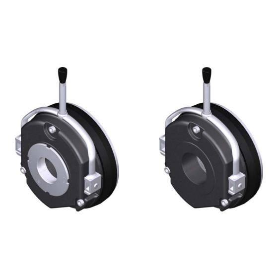
- Page 34 14.3 14.2 K14.0630 Fig. 13 Assembly of the manual release BFK458 1. Insert the compression springs (14.2) into the bore holes of the armature plate (2). 2. Push the bolts (14.5) into the bore holes of the shackle (6.1). 3. Push the hexagon head cap screw (14.4) through the compression spring (6.2) in the armature plate (2) and the bore hole in the stator (1).
-
Page 35: Electrical Installation
j | BA 14.0168 | 10/2013 Electrical installation Electrical installation Electrical connection 5.1.1 Important notes Stop! | If emergency switching off is carried out without the required suppressor circuit, the control unit may be destroyed. | Observe the correct polarity of the suppressor circuit! ... - Page 36 j | BA 14.0168 | 10/2013 Electrical installation BFKXXX-002.iso Bridge rectifier Half-wave rectifier Fig. 15 Fast engagement BFKXXX-006.iso Connection diagram also valid for star connection DC voltage (e.g. 24V) Spark suppressor Fig. 16 Separated DC voltage (fast engagement) ...
- Page 37 j | BA 14.0168 | 10/2013 Electrical installation KL-BFKXXX-003.iso Fig. 17 With microswitch (release check); connection diagram also valid for star connection DC voltage depending on coil voltage Spark suppressor KL-BFKXXX-004.iso Fig. 18 With microswitch / wear check addition for all circuits; connection diagram also valid for star connection Phone: 800.894.0412 - Fax: 888.723.4773 - Web: www.actechdrives.com - Email: info@actechdrives.com...
-
Page 38: Bridge/Half-Wave Rectifiers (Option)
Bridge/half-wave rectifiers are used for the supply of electromagnetic spring-applied DC brakes which have been released for operation with such rectifiers. Any other use is only permitted with the explicit written approval of INTORQ. Once a set overexcitation time has elapsed, the bridge/half-wave rectifiers switch over from bridge rectification to half-wave rectification. - Page 39 j | BA 14.0168 | 10/2013 Electrical installation 5.2.1 Assignment: Bridge/half-wave rectifier - brake size Rectifier type AC voltage Overexcitation Holding current reduction Coil voltage Size Coil voltage Size [V AC] [V DC] [V DC] BEG-561-255-030 06 ... 16 06 ... 14 BEG-561-255-130 ----- BEG-561-440-030-1...
- Page 40 j | BA 14.0168 | 10/2013 Electrical installation 5.2.3 Reduced switch-off times When switching on the DC side (fast engagement), switching on the AC side is also required! Otherwise, there will be no overexcitation during power-on. Delayed engagement Fast engagement ...
-
Page 41: Commissioning And Operation
j | BA 14.0168 | 10/2013 Commissioning and operation Commissioning and operation Important notes Danger! The brake must be free of residual torque. The drive must not be running when checking the brake. Danger! Live connections must not be touched. The brakes are dimensioned in such a way that the given characteristic torques are reached safely after a short run-in process. - Page 42 j | BA 14.0168 | 10/2013 Commissioning and operation Danger! Live connections must not be touched. 1. Remove two bridges from the motor terminals. Do not switch off the DC brake supply. When connecting the rectifier to the neutral point of the motor, the PE conductor must also be connected to this point.
- Page 43 j | BA 14.0168 | 10/2013 Commissioning and operation 6.2.3 Microswitch - wear check Danger! The brake must be free of residual torque. The motor must not rotate. Danger! Live connections must not be touched. 1. Remove two bridges from the motor terminals. Do not switch off the DC voltage for the brake.
- Page 44 j | BA 14.0168 | 10/2013 Commissioning and operation 6.2.4 Checking the manual release function Stop! This operational test is to be carried out additionally! Danger! The drive system must be load-free. The motor must not rotate. Fig. 20 Operating direction of lever 1.
-
Page 45: Commissioning
j | BA 14.0168 | 10/2013 Commissioning and operation Commissioning 1. Switch on drive system. 2. Carry out a braking test, if necessary, reduce brake torque. During operation Danger! The running rotor must not be touched. Danger! Live connections must not be touched. Check the brake regularly during operation. - Page 46 j | BA 14.0168 | 10/2013 Commissioning and operation 6.4.1 Brake torque reduction 1max. KL458-003-a KL458-006-a Fig. 21 Reducing the brake torque Complete stator 31 Adjuster nut 1. Turn the adjuster nut (31) counterclockwise using the hook wrench. – Observe the notches. Positions between notches are impermissible. (Values for the brake torque reduction see chapter 3.2.1).
-
Page 47: Maintenance/Repair
j | BA 14.0168 | 10/2013 Maintenance/repair Maintenance/repair Wear of spring-applied brakes The following table describes the different causes of wear and their effects on the components of the spring-applied brake. The important influencing factors must be quantified so that the service life of the rotor and brake can be calculated and that the maintenance intervals to be prescribed can be specified precisely. -
Page 48: Inspections
The maintenance operations must be carried out as described in the detailed descriptions. 7.2.1 Maintenance intervals Designs Service brake Holding brake with emergency stop BFK458- E / N according to service life at least every 2 years calculation BFK458- L after 1 million cycles at the... - Page 49 j | BA 14.0168 | 10/2013 Maintenance/repair 7.3.1 Checking the component parts 50 With assembled brake Check function of ventilation and control 50 Measure the air gap (adjust if necessary) 49 Measure the rotor thickness (replace rotor if necessary) Thermal damage to armature plate or flange (dark blue tarnishing)
- Page 50 j | BA 14.0168 | 10/2013 Maintenance/repair 7.3.4 Release / voltage Danger! The running rotor must not be touched. Danger! Live connections must not be touched. 1. Observe the brake function during operation of the drive. The armature plate must be attracted and the rotor must move without residual torque.
- Page 51 j | BA 14.0168 | 10/2013 Maintenance/repair 7.3.6 Rotor replacement Danger! The brake must be free of residual torque. 1. Switch off voltage! 2. Disconnect the supply cable. 3. Loosen the screws evenly and remove them completely. 4. Remove the complete stator from the end shield. Observe the supply cable. 5.
-
Page 52: Spare-Parts List
– The item numbers are only valid for the standard design. Please include the following information with the order: – Order number of the brake – Position number of the spare part Fig. 22 Spring-applied brake INTORQ BFK458-06 to 25 Pos. Designation Variant... - Page 53 | BA 14.0168 | 10/2013 Maintenance/repair Fig. 23 Double spring-operated brake INTORQ BFK458-06 to 25 Pos. Designation Variant Complete stator, module N Voltage / brake torque – as option with noise-reduced armature plate Complete rotor Aluminium rotor Aluminium rotor with sleeve –...
-
Page 54: Spare Parts Order
| BA 14.0168 | 10/2013 Maintenance/repair Spare parts order INTORQ BFK458- / complete stator Size Design E (with adjuster nut) N (without adjuster nut) Voltage 24 V 96 V 103 V 170 V 180 V 190 V... - Page 55 j | BA 14.0168 | 10/2013 Maintenance/repair Electrical accessories Rectifier type AC voltage Overexcitation Holding current reduction Coil voltage Size Coil voltage Size [V AC] [V DC] [V DC] BEG-561-255-030 06 ... 16 06 ... 14 BEG-561-255-130 ----- BEG-561-440-030-1 06 ... 16 ----- ----- Phone: 800.894.0412 - Fax: 888.723.4773 - Web: www.actechdrives.com - Email: info@actechdrives.com...
-
Page 56: Troubleshooting And Fault Elimination
j | BA 14.0168 | 10/2013 Troubleshooting and fault elimination Troubleshooting and fault elimination If any malfunctions should occur during operation, please check the possible causes using the following table. If the fault cannot be eliminated by one of the listed measures, please contact the aftersales service. - Page 57 j | BA 14.0168 | 10/2013 Troubleshooting and fault elimination Fault Cause Remedy Replace rotor, 51 Rotor not thick enough Rotor has not been replaced in time Voltage is not zero when checking Incorrect wiring of microswitch Check the wiring of the microswitch and correct it. the operation ...
Need help?
Do you have a question about the BFK458 and is the answer not in the manual?
Questions and answers