Table of Contents
Advertisement
Advertisement
Table of Contents

Related Manuals for Vingtor VSP 12 Way


Summary of Contents for Vingtor VSP 12 Way
- Page 1 Amplified Batteryless Telephone System VSP 12 Way TECHNICAL MANUAL A100K10873...
- Page 2 About this Document Document Scope This document is intended for qualified technicians who will install and service the VSP 12 Way Amplified Batteryless Telephone System on marine vessels. The document provides relevant information on system features, available equipment, typical configurations, simplified wiring and programming, and technical data for the system.
-
Page 3: Table Of Contents
Figure 2: Main station VSP-211-L principle diagram ....................6 Figure 3: Cabling diagram based on system configuration example ................9 Figure 4: DIP switch setting for extension no. 2 ......................10 Figure 5: Extension number label ..........................10 A100K10873 VSP 12 Way Batteryless Telephone System Technical Manual... -
Page 4: General Description
CONTROL ROOM Ext. no. 2 VSP-223-L Ext. no. 3 VSP-36-PEL EHS-24 ENGINE ROOM OPEN DECK VSP-122P Ext. no. 6 EHS-24 CD-16 VSP-36-PELP CD-4 (Ext. no. 2) Figure 1: System Configuration Example A100K10873 VSP 12 Way Batteryless Telephone System Technical Manual... -
Page 5: Station Types
1.2 Station Types The VSP 12 Way system is a range of stations with up to 12 extensions designed to provide clear and secure communication in any area and under all conditions on board a vessel or rig. The various station types can be mounted to suit particular onboard environments. -
Page 6: Functional Description
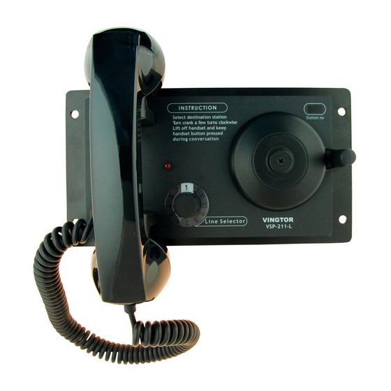
This will activate the call signal generator in the called station and provide power to the amplifier. ● The desired station is selected by a 12-way rotary switch. When turning the hand crank, a voltage is supplied to the selected line. A100K10873 VSP 12 Way Batteryless Telephone System Technical Manual... -
Page 7: Amplifier
This line is connected to the output transformer of the system amplifier located in VSP-211-L. The speaker line is marked 3 and 4 on the screw terminals in all VSP units. A100K10873 VSP 12 Way Batteryless Telephone System Technical Manual... -
Page 8: Installation
A full system with 12 stations therefore requires 8 pairs of wires. ● The screen must be connected to terminal 2 in VSP-211-L to avoid noise problems. A100K10873 VSP 12 Way Batteryless Telephone System Technical Manual... -
Page 9: Figure 3: Cabling Diagram Based On System Configuration Example
10 11 12 13 14 15 16 OPEN DECK Ext. no. 6 VSP-122P CD-16 10 11 12 13 14 15 16 Figure 3: Cabling diagram based on system configuration example A100K10873 VSP 12 Way Batteryless Telephone System Technical Manual... -
Page 10: Compass Safety
A label strip with numbers 1 to 12 is shipped with each station. ● Fix the label with the relevant extension number in the frame next to the text Station no at the front of the station. Figure 5: Extension number label A100K10873 VSP 12 Way Batteryless Telephone System Technical Manual... -
Page 11: Operation
In noisy areas, a headset with a noise compensating microphone may be connected to the station, either fixed connected or plugged into a separate plug box. A100K10873 VSP 12 Way Batteryless Telephone System Technical Manual... -
Page 12: Troubleshooting
● The oscillator in the called station may be defective. - Replace the station with one that is working. L Stations used in hazardous areas do not have a call tone oscillator. A100K10873 VSP 12 Way Batteryless Telephone System Technical Manual... -
Page 13: Specifications
«Generic immunity standard, Part 2: Industrial environment» Test reference: Report No.: 96-1196 Issued by: DET NORSKE VERITAS AS Report No.: S97 0662a and S97 0662b Issued by: Jydske EMC Lab A/S, Denmark A100K10873 VSP 12 Way Batteryless Telephone System Technical Manual... - Page 14 2011-03-15 Issued by: Registro Italiano Navale (RINA) Certificate no.: 03/00041(E1) Valid until: 2013-04-07 Issued by: Lioyd’s Register (EMEA) Certificate no.: 09.00033.262 Valid until: 2014-01-15 Issued by: Russian Maritime Register of Shipping A100K10873 VSP 12 Way Batteryless Telephone System Technical Manual...
-
Page 15: Dip Switch Settings For Extension Numbers
DIP SWITCH SETTING DIP SWITCH SETTING 10 11 12 10 11 12 - JUMPERS MUST BE INSERTED J2 J3 J2 J3 - JUMPERS MUST BE INSERTED Extension No. 6 Extension No. 12 A100K10873 VSP 12 Way Batteryless Telephone System Technical Manual... -
Page 16: Station & Mounting Dimensions
Station & Mounting Dimensions 8.1 VSP-122 A100K10873 VSP 12 Way Batteryless Telephone System Technical Manual... -
Page 17: Vsp-122P
8.2 VSP-122P A100K10873 VSP 12 Way Batteryless Telephone System Technical Manual... -
Page 18: Vsp-211-L
8.3 VSP-211-L 8.4 VSP-213-L A100K10873 VSP 12 Way Batteryless Telephone System Technical Manual... -
Page 19: Vsp-223-L
8.5 VSP-223-L A100K10873 VSP 12 Way Batteryless Telephone System Technical Manual... - Page 20 STENTOFON and VINGTOR products are developed and marketed by Zenitel Norway AS. The company’s Quality Assurance System is certified to meet the requirements in NS-EN ISO 9001:2008. Zenitel Norway AS reserves the right to modify designs and alter specifications without prior notice, in pursuance of a policy of continuous improvement. © 2010 Zenitel Norway AS.
Need help?
Do you have a question about the VSP 12 Way and is the answer not in the manual?
Questions and answers