Table of Contents
Advertisement
Advertisement
Table of Contents

Summary of Contents for Vingtor VSP-M 20 WAY
- Page 1 Amplified Batteryless Telephone System VSP-M 20 WAy TECHNICAL MANUAL A100K10758...
- Page 2 Document Scope This document is intended for qualified technicians who will install and service the VSP-M 20 Way Amplified Batteryless Telephone System on marine vessels. The document provides relevant information on system features, available equipment, typical configurations, simplified wiring and programming, and technical data for the system.
-
Page 3: Table Of Contents
Figure 2 Main station VSP-211M-L principle diagram ....................6 Figure 3 Cabling diagram based on system configuration example ................ 10 Figure 4 DIP switch setting example .........................11 Figure 5 Extension number label ..........................11 A100K10758 VSP-M 20 Way Batteryless Telephone System Technical Manual... -
Page 4: General Description
VSP-212M-L VSP-212M-L CONTROL Ext. no. 03 ROOM Ext. no. 02 VSP-36-PEL EHS-24 ENGINE ROOM OPEN DECK VSP-22M EHS-24 Ext. no. 06 VSP-36-PELP CD-4 (Ext. no. 02) Figure 1 System Configuration Example A100K10758 VSP-M 20 Way Batteryless Telephone System Technical Manual... -
Page 5: Station Types
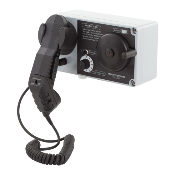
Station Types The VSP-M 20 Way system is a range of stations with up to 20 extensions designed to provide clear and secure communication in any area and under all conditions on board a vessel or rig. The various station types can be mounted to suit particular onboard environments. -
Page 6: Functional Description
L Note that the circuit boards can be used as spare parts for the older VSP units. When using boards with inductors, remove jumpers from pins J6 and J7/J8 and insert a jumper on pin J9 located to the left of the DIP switches. A100K10758 VSP-M 20 Way Batteryless Telephone System Technical Manual... -
Page 7: Calling
- Calls to a station in a hazardous area will be indicated by use of EX approved audible or visible signal units. - When VSP-512 is called, a relay in the buffer unit will be activated and necessary power for the signal devices will be supplied. A100K10758 VSP-M 20 Way Batteryless Telephone System Technical Manual... -
Page 8: Handset
This line is connected to the output transformer of the system amplifier located in VSP-211M-L. The speaker line is marked 3 and 4 on the screw terminals in all VSP-M units. A100K10758 VSP-M 20 Way Batteryless Telephone System Technical Manual... -
Page 9: Installation Instructions
Group 0 and Group 1 (1 pair). A full system with 20 stations therefore requires 8 pairs of wires. ● The screen must be connected to terminal 2 in VSP-211M-L to avoid noise problems. A100K10758 VSP-M 20 Way Batteryless Telephone System Technical Manual... -
Page 10: Figure 3 Cabling Diagram Based On System Configuration Example
VSP-213M-L + VSPK stop IRR-VSPM-24 IRR-VSPM-220 10 11 12 13 14 OPEN DECK Ext. no. 05 VSP-22M 10 11 12 13 14 Figure 3 Cabling diagram based on system configuration example A100K10758 VSP-M 20 Way Batteryless Telephone System Technical Manual... -
Page 11: Compass Safety
A label strip with numbers 00 to 19 is shipped with each station. ● Fix the label with the relevant extension number in the frame next to the text Station no at the front of the station. Figure 5 Extension number label A100K10758 VSP-M 20 Way Batteryless Telephone System Technical Manual... -
Page 12: Operation
In noisy areas, a headset with a noise compensating microphone may be connected to the station, either fixed-connected or plugged into a separate plug box. A100K10758 VSP-M 20 Way Batteryless Telephone System Technical Manual... -
Page 13: Troubleshooting
● The oscillator in the called station may be defective. - Replace the station with one that is working. L Stations used in hazardous areas do not have a call tone oscillator. A100K10758 VSP-M 20 Way Batteryless Telephone System Technical Manual... -
Page 14: Specifications
«Generic immunity standard, Part 2: Industrial environment» Test reference Report No.: 96-1196 Issued by: DET NORSKE VERITAS AS Report No.: S97 0662a and S97 0662b Issued by: Jydske EMC Lab A/S, Denmark A100K10758 VSP-M 20 Way Batteryless Telephone System Technical Manual... - Page 15 2011-03-15 Issued by: Registro Italiano Navale (RINA) Certificate no.: 03/00041(E1) Valid until: 2013-04-07 Issued by: Lioyd’s Register (EMEA) Certificate no.: 09.00033.262 Valid until: 2014-01-15 Issued by: Russian Maritime Register of Shipping A100K10758 VSP-M 20 Way Batteryless Telephone System Technical Manual...
-
Page 16: Dip Switch Settings For Extension Numbers
J2 J3 - REMOVE JUMPERS Extension N Extension N DIP SWITCH SETTING DIP SWITCH SETTING 10 11 12 10 11 12 J2 J3 - REMOVE JUMPERS J2 J3 - REMOVE JUMPERS Extension N Extension N A100K10758 VSP-M 20 Way Batteryless Telephone System Technical Manual... -
Page 17: Station & Mounting Dimensions
Station & Mounting Dimensions VSP-211M-L VSP-212M-L A100K10758 VSP-M 20 Way Batteryless Telephone System Technical Manual... -
Page 18: Vsp-213M-L
VSP-213M-L VSP-22M A100K10758 VSP-M 20 Way Batteryless Telephone System Technical Manual... - Page 19 A100K10758 VSP-M 20 Way Batteryless Telephone System Technical Manual...
- Page 20 A100K10758 VINGTOR products are developed and marketed by Zenitel Norway AS. The company’s Quality Assurance System is certified to meet the requirements in NS-EN ISO 9001:2008. Zenitel Norway AS reserves the right to modify designs and alter specifications without prior notice, in pursuance of a policy of continuous improvement. ©2010 Zenitel Norway AS.


Need help?
Do you have a question about the VSP-M 20 WAY and is the answer not in the manual?
Questions and answers