Table of Contents
Advertisement
Quick Links
Multiprotocol Ethernet Interface
Thank you for purchasing the A1-ETHERNET Multiprotocol Ethernet Interface.
This product is designed to connect the iMASTER Standard A1 series of inverters to Ethernet
•
communication networks. Please read this instruction manual thoroughly in order to become
familiar with the proper interface handling, installation and usage procedures.
Improper handling may inhibit correct operation or cause premature interface failure.
•
Please deliver this instruction manual to the end user of the interface, and retain it in an
•
accessible location.
For inverter usage instructions, please refer to the applicable inverter instruction manual.
•
January 3, 2017
Part #11010
A1-ETHERNET
Instruction Manual
© 2017 ADT
Advertisement
Table of Contents

Summary of Contents for ADT A1-ETHERNET
- Page 1 Instruction Manual A1-ETHERNET Multiprotocol Ethernet Interface Thank you for purchasing the A1-ETHERNET Multiprotocol Ethernet Interface. This product is designed to connect the iMASTER Standard A1 series of inverters to Ethernet • communication networks. Please read this instruction manual thoroughly in order to become familiar with the proper interface handling, installation and usage procedures.
- Page 2 Printed in U.S.A. ©2017 ADT All rights reserved ADT reserves the right to make changes and improvements to its products without providing notice. Notice to Users PRODUCTS ARE NOT AUTHORIZED FOR USE AS CRITICAL COMPONENTS IN LIFE-SUPPORT DEVICES OR SYSTEMS. Life-support devices or systems are devices or systems intended to sustain life, and whose failure to perform, when properly used in accordance with instructions for use provided in the labeling and user's manual, can be reasonably expected to result in significant injury.
-
Page 3: Safety Precautions
This instruction manual has been prepared to help you connect your iMASTER Standard A1 inverter to Industrial Ethernet networks using the A1-ETHERNET Multiprotocol Ethernet interface card. This instruction manual does not contain inverter usage instructions. Please refer to this instruction manual in conjunction with the applicable inverter instruction manual in order to become familiar with the proper handling, installation and operation of this product. -
Page 4: Installation And Wiring
Installation and Wiring To avoid electrical shock, remove all power from the inverter and wait at least five minutes prior to • starting installation. Additionally, confirm that the DC link bus voltage as measured between the P (+) and N (-) terminals is less than 25 VDC. Installation should be performed only by qualified personnel. - Page 5 Maintenance, inspection, and parts replacement To avoid electrical shock, remove all power from the inverter and wait at least five minutes prior to • starting inspection. Additionally, confirm that the DC link bus voltage as measured between the P (+) and N (-) terminals is less than 25 VDC. Maintenance, inspection, and parts replacement should be performed only by qualified personnel.
-
Page 6: Table Of Contents
Output frequency monitor (01.01) ..................22 4.3.4 Rotation direction monitor (01.04) ..................22 4.3.5 Trip monitor ........................22 ADT FIELDBUS OPTION CONFIGURATION STUDIO ......23 Overview ......................... 23 General Object Editing Activities ................. 25 Ethernet Settings ....................26 5.3.1 Authentication ........................26 5.3.2... - Page 7 Overview ......................... 31 Monitor Tab ......................31 6.2.1 Information Window ......................31 6.2.2 Parameter Group Selection List ..................32 6.2.3 Parameter List ......................... 32 6.2.4 Parameter List Filter ......................33 6.2.5 Radix Selection ........................ 33 Dashboard Tab ....................... 34 6.3.1 Information Window ......................
- Page 8 9.2.12.1 ControlLogix Example: Generic Default I/O Add-On Instruction ........ 61 9.2.12.2 ControlLogix Example: AC/DC Drive Profile Add-On Instruction ....... 62 9.2.13 ControlLogix Example: Read Parameters ................ 64 9.2.14 ControlLogix Example: Reading and Writing MSG Instructions ........68 Allen Bradley CSP (PCCC) ..................69 9.3.1 Overview .........................
-
Page 9: Pre-Operation Instructions
1 PRE-OPERATION INSTRUCTIONS Product Overview The A1-ETHERNET Multiprotocol Ethernet interface allows information to be transferred seamlessly between an iMASTER Standard A1 inverter and several Ethernet-based fieldbus networks with minimal configuration requirements. The interface installs directly onto the inverter, and presents two RJ-45 jacks with an embedded 10BASE-T/100BASE-TX Ethernet switch for connection to the Ethernet network. - Page 10 Table 2: General Hardware Specifications Item Description Power Supply Directly powered by the inverter LED Indicators Module Status, Network Status, 2 x Ethernet Link/Activity USB Port USB 2.0, mini-B 5-pin Table 3: Ethernet Hardware Specifications Item Description Number of Ports 2 (internal switch) Standard IEEE 802.3 10BASE-T/100BASE-TX Ethernet compliant...
- Page 11 Table 5: EtherNet/IP Specifications Item Description Conformance Tested ODVA EtherNet/IP Conformance Test Software Version CT-13 Product Type Code 2 (AC Drive) AC/DC Drive Profile UCMM Class 3 (Explicit) Messaging Class 1 (Implicit I/O) Messaging Class 1 Unicast T→O Class 1 Multicast T→O Number of Connections 16 (Total for both Class 1 and Class 3) Min 1ms...
- Page 12 Table 6: Allen Bradley CSP (PCCC) Specifications Item Description Read Services PLC5 Read (DF1 protocol typed read, 0x68) Write Services PLC5 Write (DF1 protocol typed write, 0x67) Data Type 16-bit Integer File Type N (Integer) Logical ASCII Addressing Logical Binary Addressing Max Read Size 240 bytes (120 16-bit Integers) Max Write Size...
- Page 13 Item Description I/O Cycle Time Min 1ms I/O Input Size Max 32 input words, user configurable I/O Output Size Max 32 output words, user configurable Media Redundancy Protocol Client Discovery, set station name, set IP address LLDP I&M I&M0 Alarms Plug, Pull Number of Controllers Allows access to only 1 controller...
- Page 14 Table 11: Environmental Specifications Item Description Indoors, less than 1000m above sea level, do not expose to direct Operating Environment sunlight or corrosive / explosive gasses Operating Temperature -10 ∼ +50°C (+14 ∼ +122°F) Storage Temperature -40 ∼ +85°C (-40 ∼ +185°F) Relative Humidity 20% ∼...
-
Page 15: Component Overview
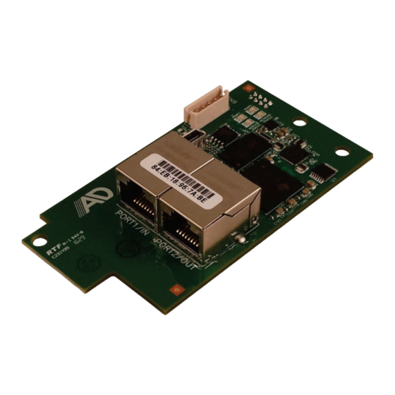
MAC Address Port 1 Ethernet jack Port 2 Ethernet jack Figure 1: A1-ETHERNET Component Overview Port 1 and Port 2 Ethernet Jacks Either jack can freely be used in star topology networks (with external switch). In linear topologies, a series of cards can be connected together by daisy-chaining one of the ports to the next inverter in line. -
Page 16: Led Indicators
LED Indicators 1.4.1 Ethernet Link/Activity LEDs LED Activity Status Note A valid Ethernet link exists: communication is Green On Link possible on this port A valid Ethernet link does not exist: communication is Green Off No Link not possible on this port Indicates when a packet is transmitted or received on Red Blink Activity... -
Page 17: Ethercat Led Description
1.4.3 EtherCAT LED Description 1.4.3.1 Module Status LED (Run) LED Activity Slave State Note Device Off or The inverter power is off or the device is in the INIT INITIALISATION state Green Blink, Startup blink sequence; the device is booting and Red Blink or INITIALISATION has not yet entered the INIT state... -
Page 18: Installation
2 INSTALLATION Pre-Installation Instructions Installation Procedure... -
Page 19: Inverter Parameter Settings
3 INVERTER PARAMETER SETTINGS The inverter parameters listed in Table 12 are required for proper operation of the end-to-end communication system. Although there may be many other parameters that will require configuration for your specific application, it is important to understand the manner in which the following parameters will impact successful control of the inverter. -
Page 20: Parameter Numbering And Behavior
4 PARAMETER NUMBERING AND BEHAVIOR Register Numbers All accessible inverter parameters can be referenced by their Modbus register indices, as defined in the A1 Instruction Manual and can be conveniently referenced in the studio (section 5.6) and the embedded web server (section 6.2.3). These same register numbers are used when accessing parameters via certain Ethernet protocols. - Page 21 Table 13: Parameter Groups Group Number Group Name Group Number Group Name Special parameters DWELL VFD running status Frequency limits Frequency reference indication Fault functions Trip information Motor thermal protection Time counter System overload/underload VFD firmware information Standard DI, DO DBR duty cycle Standard AI (O, OI) Monitoring/Scaling...
-
Page 22: Scanned Parameters
Scanned Parameters The interface card provides network access to the specified list of parameters contained in the param.xml file located in the “WEB” folder of the interface card’s file system. These parameters are constantly being read and/or written (as applicable), and their current values are therefore mirrored in the interface card’s internal memory. -
Page 23: Output Frequency Monitor (01.01)
4.3.3 Output frequency monitor (01.01) Parameter 01.01 (register 258) is the present output frequency. The output frequency is represented in units of 0.01Hz. For example, if the inverter is running at 60.00Hz, the value read is (60.00Hz / 0.01Hz) = 6000 (decimal) or 0x1770 (hexadecimal). -
Page 24: Adt Fieldbus Option Configuration Studio
5 ADT FIELDBUS OPTION CONFIGURATION STUDIO 5.1 Overview The interface card is discovered, configured and updated by the ADT Fieldbus Option Configuration Studio PC application (refer to Figure 2). The studio must be installed prior to connecting an interface card to the computer in order to ensure that the appropriate USB drivers are installed. The studio requires a USB connection for reading/writing a configuration and updating the firmware. - Page 25 Going Online with a Device All connected devices are automatically added to the Discovered Devices panel. This panel is shown by selecting the Online Devices list heading in the Project panel. To go online with a device: Double-click on it in the Discovered Devices panel. •...
-
Page 26: General Object Editing Activities
Stop all other communication to the device when downloading. Updating Firmware The studio automatically manages firmware updates when going online with a device and downloading a configuration to a device. Download the latest studio to obtain the latest firmware. Do not power off the device or interrupt the connection once the update is in progress as this may corrupt the firmware and/or the configuration. -
Page 27: Ethernet Settings
Copying and Pasting an Object To copy an object, first click on an item in the Project panel. An object can then be copied by: Right-clicking on it and choosing Copy from the context-sensitive menu. • Pressing the <CTRL+C> keys on the keyboard. •... -
Page 28: Internal Logic Settings
5.4 Internal Logic Settings 5.4.1 Fail-safe Values 5.4.1.1 Overview The card can be configured to perform a specific set of actions when network communications are lost (timeout event). This allows each inverter parameter to have its own unique “fail-safe” condition in the event of network interruption. -
Page 29: Discovery Over Ethernet
Figure 4: Timeout Object Settings The example is complete. Discovery over Ethernet Depending on the currently-enabled driver, the Configuration Studio will automatically discover the device on the Ethernet network, regardless of whether or not the card’s network settings are compatible with the subnet upon which they reside. -
Page 30: Backup And Restore Parameters
A parameter is accessible and actively scanned (read from and written to the inverter) only if its corresponding checkbox is enabled. Likewise, a parameter is inaccessible if its checkbox is disabled. Parameters that are accessed more frequently or require a faster update rate should be set to high priority. -
Page 31: Restore Factory Settings
Figure 9: Restore Parameters Restore Factory Settings The interface card (connected via USB) can be restored to the factory settings. Note that the filesystem will be reformatted, which will destroy all custom modifications and configurations. Please backup the configuration before executing this feature. The factory settings can be restored by: Right-clicking on the device in the Project panel and choosing Restore Factory Settings. -
Page 32: Embedded Web Server
6 EMBEDDED WEB SERVER Overview The interface contains an embedded web server (also known as an HTTP server), which allows users to access the inverter’s internal data in a graphical manner with web browsers such as Microsoft Internet Explorer or Mozilla Firefox. In this way, the inverter can be monitored and controlled from across the room or from across the globe. -
Page 33: Parameter Group Selection List
6.2.2 Parameter Group Selection List The Parameter Group Selection List is shown in Figure 12. Individual groups can be selected by clicking on the group name. Multiple groups may also be selected by holding down the CTRL key while clicking on the group names, or a range of groups can be selected by first Figure 12: Parameter Group Selection List... -
Page 34: Parameter List Filter
6.2.4 Parameter List Filter A filter function provides Parameter List search capabilities. To use the filter function, simply type a word or portion of a word into the filter entry box and then click the “filter” button. Refer to Figure 14. The Figure 14: Parameter List Filter filter will then display only those parameters currently available in the Parameter List that satisfy the search... -
Page 35: Dashboard Tab
Dashboard Tab The Dashboard Tab provides access to a virtual keypad, as well as a variety of gauges, meters and graphs that can be configured to provide an at-a-glance graphical overview of critical application variables in real-time. A total of 10 gauge windows are available (four at a time), and each gauge window can be configured to display any scanned parameter’s value via one of six different gauge types. - Page 36 Units: A text entry box in which the user can enter an engineering units string comprised of up to 8 characters. This units string will be appended to all locations in the gauge window that display the designated parameter’s current value. Parameter: The designated parameter whose value is to be reflected on the gauge.
- Page 37 Meter: Refer to Figure 20. This type of meter implements a common panel meter-type display format. The units string is shown on the face of the meter. All raw parameter values are interpreted as positive numbers (i.e. 0...0xFFFF equates to 0...65535 Figure 20: Meter Pos/Neg Meter: Refer to Figure 21.
-
Page 38: Submitting Changes
At times, it may be convenient to zoom in on a particular gauge or meter in order to more clearly see the indicator, or to fill the computer screen with a particular gauge’s image. This can be easily accomplished with the web browser’s Flash Player plug-in by right- clicking on the gauge and selecting the desired zoom level (refer to Figure 24). -
Page 39: Customizing The Embedded Web Server
Customizing the Embedded Web Server 6.4.1 Customization Overview It is possible for end-users to customize the embedded web server in order to create their own application-specific or corporate “look and feel”. Knowledge of authoring dynamic web content is required. Using windows explorer, it is possible to load customized web server content into the “WEB” folder on the interface card’s file system (refer to section 7.2). -
Page 40: Xtpro Web Browser-Based Implementation
6.4.3 XTPro Web Browser-Based Implementation A representative implementation based upon using a web browser as the client is detailed in Figure 26. In this scenario, the client application is developed by using an active web server authoring tool (such as Adobe Flash®). -
Page 41: Xtpro Hmi-Based Implementation
6.4.4 XTPro HMI-Based Implementation A representative implementation based upon a stand-alone HMI client is detailed in Figure 27. In this scenario, the client application is developed by using tools provided by the HMI manufacturer, and is hosted independently of the actual server device. trogrammer authors HMI (client) content Content is loaded... -
Page 42: File System
7 FILE SYSTEM Overview The interface card’s on-board file system is used by the application firmware. Currently, the application firmware’s main use of the file system is to store XML-encoded configuration files and the embedded web server. The studio must be used to manage the configuration via USB or FTP. Do not manually access the configuration files unless instructed by technical support. -
Page 43: Ftp With Windows Explorer
Figure 30: USB File Access via Windows Explorer FTP with Windows Explorer To use FTP with Microsoft Windows Explorer, first open either “Windows Explorer” or “My Computer”. Please note that the indicated procedure, prompts and capabilities outlined here can vary depending on such factors as the installed operating system, firewalls and service packs. - Page 44 Navigate to the card’s file system (see section 7.2 or 7.3). Backup the “WEB” folder if desired by copying it to the local computer. Delete the “WEB” folder from the card’s file system. Copy the new “WEB” folder to the card’s file system. Although it is not typical, if your param.xml file was specially modified (for a custom application, for example), it may be necessary to re-apply those modifications.
-
Page 45: Firmware
8 Firmware Overview The interface card’s embedded firmware can be updated in the field. Firmware updates may be released for a variety of reasons, such as custom firmware implementations, firmware improvements and added functionality as a result of user requests. Additionally, it may be necessary to load different firmware onto the unit in order to support various protocols. -
Page 46: Protocol-Specific Information
9 PROTOCOL-SPECIFIC INFORMATION This section will discuss topics that are specific to each of the supported protocols. Modbus/TCP 9.1.1 Overview The interface card supports Schneider Electric’s Modbus/TCP protocol, release 1.0. The interface is conformance class 0 and partial class 1 and class 2 compliant, and allows up to 8 simultaneous Modbus/TCP client connections (sockets). -
Page 47: Connection Timeout Options
#3, bit #1. 9.1.4 Connection Timeout Options In the studio’s Project panel, navigate to A1-ETHERNET…Ethernet…Modbus/TCP Server. The following configuration options will determine the actions to be taken if the connection is abnormally terminated or lost. While this feature provides an additional level of fail-safe functionality for those applications that require it, there are several ramifications that must be understood prior to enabling this capability. -
Page 48: Node Settings
There are no node settings. A node is simply a container for objects. 9.1.6 Holding/Input Register Remap Settings In the studio’s Project panel, add A1-ETHERNET…Ethernet…Modbus/TCP Server…Node…Holding/Input Register Remap. The holding/input register remap objects are OPTIONAL. By default, all inverter parameters are already mapped as both holding (4X) and input (3X) registers (refer to section 9.1.2). -
Page 49: Ethernet/Ip
1 connections. 9.2.2 Server Settings In the studio, navigate to A1-ETHERNET…Ethernet…EtherNet/IP Server. Device Name The device name is used for identification of a device on the EtherNet/IP network. This string is accessible as the “product name”... -
Page 50: Connection Timeout Options
9.2.3 Connection Timeout Options In the studio’s Project panel, navigate to A1-ETHERNET…Ethernet…EtherNet/IP Server. The following configuration options will determine the actions to be taken if the connection is abnormally terminated or lost. While this feature provides an additional level of fail-safe functionality for those applications that require it, there are several ramifications that must be understood prior to enabling this capability. -
Page 51: Generic Class 1 (I/O) Connection Access
Data Type Each data word is fixed to 16-Bit Unsigned. This is equivalent to two bytes. Table 19: EtherNet/IP User-Configurable I/O Data Format Consumed Data Produced Data (PLC to Inverter) (Inverter to PLC) Word Offset Parameter Word Offset Parameter The default I/O configuration is described in Table 20. Always use the studio to confirm the configuration before commissioning the device Table 20: EtherNet/IP Default User-Configurable I/O Data Format Consumed Data... - Page 52 interoperability among different vendor’s products. This section will focus primarily on the format of the AC/DC drive profile I/O assemblies supported by the interface card, and the inverter data which their various constituent elements map to. Table 22: Output Instances 20 and 21 Detail Instance Byte Bit 7...
-
Page 53: Explicit Messaging Via Get/Set Attribute Single Services
Input Instance Mapping Detail Faulted: Inverter fault signal (0=not faulted, 1=faulted). Maps to parameter 03.01 (current trip source). Warning: This bit is not used (it is always 0). Running1 (FWD): Running forward status signal (0=not running forward, 1=running forward). Maps to parameter 01.04 (rotation direction). -
Page 54: Inverter Parameter Access Tag Format
9.2.9 Inverter Parameter Access Tag Format Any inverter parameter (in section 4) can be accessed with its own unique tag name, or an array tag can be used to access a group of parameters with one PLC instruction. The “tag name” is essentially the ASCII representation of the parameter itself. -
Page 55: Controllogix Example: Eds Add-On Profile (Aop)
The “New Module” window will open. Refer to Figure 33. Figure 33: Identifying the New Module Assign the Ethernet module a name (we will use “EIP”) and an IP address, deselect “Open Module Properties”, and click OK. Download the configuration. Switch to online mode. - Page 56 Figure 35: EDS Registration Click “Browse”, select the interface card’s EDS file, and click “Next”. Ensure that there are no errors in the test results. Click “Next”. A graphic image of the interface card is displayed. Click “Next”. The task summary will list the interface card as the device to register. Click “Next”. “You have successfully completed the EDS Wizard”.
- Page 57 The “New Module” properties dialog box will open as shown in Figure 37. Figure 37: AOP Interface Card Module Properties Enter a “Name” which will allow easy identification of the inverter on the network (the tags created in RSLogix 5000 will be derived from this “Name”). Enter the “IP address” of the targeted interface card.
-
Page 58: Controllogix Example: Eds Add-On Profile (Aop) Generic I/O Messaging
You should now see the interface card in the 1756-ENBT/A branch under the I/O Configuration in the controller organizer view. The full I/O Configuration tree should appear similar to Figure 39. Figure 39: AOP Interface Card I/O Configuration Continue with the AOP Generic I/O Messaging example in section 9.2.11.1 or AOP AC/DC Drive Profile example in section 9.2.11.2. -
Page 59: Controllogix Example: Eds Add-On Profile (Aop) Ac/Dc Drive Profile
9.2.11.2 ControlLogix Example: EDS Add-On Profile (AOP) AC/DC Drive Profile This section will demonstrate how to configure the EtherNet/IP AC/DC drive profile I/O connection. Complete all steps in section 9.2.11. Locate the interface card in the 1756-ENBT/A branch under the “I/O Configuration” in the controller organizer view. - Page 60 Figure 42: Adding a New Generic Ethernet Module The module properties dialog box will open (refer to Figure 43). Enter a Name which will allow easy identification of the inverter on the network (the tags created in RSLogix 5000 will be derived from this Name).
- Page 61 Configuration: The Configuration Assembly Instance is unused, and its instance number and size are therefore irrelevant (you can just enter “1” and “0”, respectively). When done, click “OK”. You should now see the new module (named “ETHERNET-MODULE Interface_Card”) in the 1756-ENBT/A branch under the I/O Configuration in the controller organizer view.
-
Page 62: Controllogix Example: Generic Default I/O Add-On Instruction
Figure 47: Controller Tags for I/O Access We can directly interact with these tags in order to control and monitor the inverter. In Figure 47, for example, we can see that the first 16-bit word of output data (Interface_Card:O.Data[0]) has been set to a hexadecimal value of 0x0001. -
Page 63: Controllogix Example: Ac/Dc Drive Profile Add-On Instruction
Double click “MainRoutine” under Tasks …MainTask …MainProgram in the controller organizer view. Right click on the first ladder logic rung in the MainRoutine window and select “Add Ladder Element...” The “Add Ladder Element” window appears. Select the generic default I/O add-on instruction in the Add-On folder. - Page 64 Right click on “Add-On Instructions” in the controller organizer view and select “Import Add-On Instruction”. Browse and import the AC/DC drive profile add-on instruction. Refer to Figure 53. Double click “Controller Tags” in the controller organizer view and select the “Edit Tags” tab at the bottom. Create the tags in Figure 54.
-
Page 65: Controllogix Example: Read Parameters
Figure 56: Configure AC/DC Drive Profile AOI The program is now complete. Save, download and run the program. 9.2.13 ControlLogix Example: Read Parameters This example program will show how to continuously read a block of parameters from the inverter with a single MSG instruction. - Page 66 Add a MSG instruction to the main program. Double click “MainRoutine” under Tasks …MainTask …MainProgram in the controller organizer view. Right click on the first ladder logic rung in the MainRoutine window and select “Add Ladder Element...” The “Add Ladder Element” window appears.
- Page 67 Click the message configuration button (“…”) in the MSG instruction. The “Message Configuration” window will open. Refer to Figure 61. Figure 61: MSG Instruction Configuration “Configuration” tab settings: Change the “Message Type” to “CIP Data Table Read”. In the "Source Element” field, enter the read tag you wish to access (refer to section 9.2.9).
- Page 68 Click “OK” to close the MSG Configuration dialog. At this stage, MainRoutine should look like Figure 63. Figure 63: MainRoutine Assign a tag to the XIO element. Double-click on the XIO element located to the left of the MSG block. In the drop-down box, double-click on the “connection.EN”...
-
Page 69: Controllogix Example: Reading And Writing Msg Instructions
9.2.14 ControlLogix Example: Reading and Writing MSG Instructions Often times, applications may need to both read data from and write data to the inverter. To accomplish this task, multiple MSG instructions will need to be implemented in the PLC program. The configuration and execution for implementing multiple MSG instructions is in general identical to that required for implementing just one MSG instruction. -
Page 70: Allen Bradley Csp (Pccc)
Allen Bradley CSP (PCCC) 9.3.1 Overview Ethernet-enabled Allen-Bradley legacy PLCs (such as the PLC5E, SLC-5/05, and MicroLogix series) use a protocol called CSP (Client Server Protocol) to communicate over the Ethernet network. The flavor of CSP used by these PLCs is also known as “PCCC” (Programmable Controller Communication Commands) and “AB Ethernet”. - Page 71 Table 25: Examples of EtherNet/IP-Style Bulk Access via File N50 File/Section Address Start Target Parameter of Max Number of Offset/Element Number Format Configuration Array Accessible Elements N50:0 N50:15 16th N50:31 32nd The application PLC program uses a MSG instruction that is configured with a “Data Table Address” from which to start the access and a “Size in Elements”...
-
Page 72: Slc-5/05 Example: Read Parameters
9.3.4 SLC-5/05 Example: Read Parameters This example program will show how to continuously read a block of parameters from the inverter with a single MSG instruction. This action is performed via the Typed Read (a.k.a. “PLC5 Read”) message type. Only one read request is outstanding at any given time. Note that the steps for the MicroLogix and PLC5E may vary slightly, but in general are similar. - Page 73 Figure 70: MSG Instruction Selection Select the “XIO” instruction from the “Bit” classification, then click OK. Refer to Figure 71. Figure 71: XIO Instruction Selection Configure the MSG instruction. Set the “Read/Write” field to “Read”, “Target Device” field to “PLC5”, “Local/Remote” field to “Local”, and “Control Block”...
- Page 74 Figure 72: MSG Configuration, "General" Tab In this example, we will be reading a total of 21 parameters beginning at N12:58 (register 258 / parameter 01.01). To configure this, under “This Controller” set the “Data Table Address” field to N18:1, set the “Size in Elements field” to 21, and set the “Channel” field to 1 (Ethernet).
- Page 75 Figure 74: PLC Program after MSG Instruction Configuration Assign a tag to the XIO element. Double-click on the XIO element located to the left of the MSG block. Type in N20:0/15 (MSG instruction’s enable bit). This configuration causes the MSG instruction to automatically retrigger itself when it completes.
- Page 76 Figure 76: Monitoring the Data Being Read from the Inverter...
-
Page 77: Slc-5/05 Example: Reading And Writing Multiple Msg Instructions
9.3.6 SLC-5/05 Example: Reading and Writing Multiple MSG Instructions Often times, applications may need to both read data from and write data to the inverter. To accomplish this task, multiple MSG instructions will need to be implemented in the PLC program. The configuration and execution for implementing multiple MSG instructions is in general identical to that required for implementing just one MSG instruction. -
Page 78: Bacnet/Ip
The BACnet driver does not trigger timeout events (section 5.4.1). • 9.4.1 Protocol Implementation Conformance Statement BACnet Protocol Date: January 3, 2017 Vendor Name: ICC, Inc. Product Name: ADT iMASTER Standard A1 Product Model Number: A1-ETHERNET Applications Software Version: V1.1.0 Firmware Revision: V1.1.0 BACnet Protocol Revision: Product Description: The iMASTER Standard A1 series is an industrial general purpose inverter. - Page 79 Device Address Binding: Is static device binding supported? (This is currently for two-way communication with MS/TP slaves and certain other devise.) Networking Options: Router, Clause 6 - List all routing configurations Annex H, BACnet Tunneling Router over IP BACnet/IP Broadcast Management Device (BBMD) Does the BBMD support registrations by Foreign Devices? Character Sets Supported: Indicating support for multiple character sets does not imply that they can all be supported...
- Page 80 Object Types/Property Support Tables: Table 26: BACnet Device Object Types /Properties Supported Object Type Property Device Object Identifier Object Name Object Type System Status Vendor Name Vendor Identifier Model Name Firmware Revision Appl Software Revision Protocol Version Protocol Revision Services Supported Object Types Supported Object List Max APDU Length...
- Page 81 Table 28: BACnet Analog Object Types /Properties Supported Object Type Property Analog Analog Analog Input Output Value Object Identifier Object Name Object Type Present Value Status Flags Event State Out-of-Service Units Priority Array Relinquish Default R – readable using BACnet services W –...
-
Page 82: Default Supported Objects
9.4.2 Default Supported Objects This section will describe the default objects. Since the objects are configurable, the system integrator is responsible for managing, maintaining, and documenting the actual configuration. Always use the studio to confirm the configuration before commissioning the device Table 30: Binary Output Object Instance Summary Active/ Instance ID... -
Page 83: Default Supported Object Details
AO3..Sets the deceleration time in 0.1 second units. Corresponds to parameter 23.05. 9.4.4 Server Settings In the studio’s Project panel, navigate to A1-ETHERNET…Ethernet…BACnet/IP Server. UDP Port This is the UDP port on which to transmit and receive BACnet/IP packets on the local subnet. The default value is 47808 (0xBAC0). -
Page 84: Analog Input Object Settings
9.4.8 Analog Input Object Settings Object Name The name of the BACnet object. Enter a string of between 1 and 32 characters in length. All object names must be unique within a node. Instance The BACnet object’s instance number. Enter a value between 0…4194302 (0x0…0x3FFFFE). Parameter The inverter parameter (in section 4) that the BACnet object’s present value will access. -
Page 85: Binary Input Object Settings
Parameter The inverter parameter (in section 4) that the BACnet object’s present value will access. Data Type Fixed to 16-bit Unsigned. Units Select the desired units from this dropdown menu. If the desired units are not available in the dropdown menu, select “Other Units”... -
Page 86: Binary Output Object Settings
9.4.12 Binary Output Object Settings Object Name The name of the BACnet object. Enter a string of between 1 and 32 characters in length. All object names must be unique within a node. Instance The BACnet object’s instance number. Enter a value between 0…4194302 (0x0…0x3FFFFE). Parameter The inverter parameter (in section 4) that the BACnet object’s present value will access. -
Page 87: Multi-State Input Object Settings
Data Type Fixed at 16-Bit Unsigned. Bitmask Specifies which bit(s) in the 16-bit value designated by the “Parameter” that the binary object will map to. This mechanism allows up to 16 binary objects to be simultaneously assigned to one parameter (each binary object mapping to a single bit of that 16-bit word). -
Page 88: Multi-State Value Object Settings
Relinquish Default Defines the default value to be used for an object’s present value property when all entries in the object’s priority array are NULL. 9.4.16 Multi-state Value Object Settings Object Name The name of the BACnet object. Enter a string of between 1 and 32 characters in length. All object names must be unique within a node. -
Page 89: Profinet Io
PROFINET specification. 9.5.3 Connection Timeout Options In the studio’s Project panel, navigate to A1-ETHERNET…Ethernet…PROFINET IO. The following configuration options will determine the actions to be taken by the card if the PROFINET IO connection is abnormally terminated or lost. -
Page 90: Profidrive Profile
not defined, the value will default to 0. The size of the actual I/O produced and consumed data is determined by the PROFINET controller. The I/O data format is summarized in Table 33. Description This 32-character (max) field is strictly for user reference: it is not used at any time by the driver. Produced Data Word Offset The value from the associated inverter parameter will populate this word offset of the produced data that is to be sent to the controller. -
Page 91: Profidrive Standard Telegram 1
Some other notes of interest include: Implements Application Class 1 (standard drive) • • Supports only Standard Telegram 1 (ST1, PZD-2/2) on slot 1 (similar to PROFIBUS PPO type 3) Supports only Speed Control Mode • 9.5.5.1 PROFIdrive standard telegram 1 The standard telegram 1 mapping is described in Table 35. -
Page 92: Profidrive Reference Speed Setpoint And Actual Speed
Value Significance Description Operation Disabled Running disabled Fault Present Inverter tripped. Refer to parameter 03.01. No Fault No trip present. Refer to parameter 03.01. Coast Stop Not Activated Follows STW1 bit 1, ON2 active Coast Stop Activated Follows STW1 bit 1, OFF2 active Quick Stop Not Activated Follows STW1 bit 2, ON3 active Quick Stop Activated... -
Page 93: Profidrive State Diagram
9.5.5.4 PROFIdrive state diagram The state diagram is displayed in Figure 79. Figure 79: PROFIdrive State Diagram 9.5.5.5 PROFIdrive-specific parameters The PROFIdrive-specific parameters are shown in Table 38. The parameters are read-only. Table 38: PROFIdrive-Specific Parameters Index Description None NSOLL_A – Speed setpoint A None NIST_A –... -
Page 94: Acyclic Data Access
9.5.6 Acyclic Data Access Any inverter parameter can be accessed via PROFINET acyclic services. To accomplish this, set the API to 0, Slot to 1 and SubSlot to 1. The record number/index value is equivalent to the desired parameter register number described in section 4.1. The length is specified according to the number of bytes to access. -
Page 95: Add The Device To The Configuration
Figure 82: Updated GSDML Device Tree 9.5.7.2 Add the device to the configuration Select the device in the Hardware catalog and drag the device onto the PROFINET IO system configuration as shown in Figure 83. Figure 83: Add Device to Configuration 9.5.7.3 Select the IO controller On the device, click “Not assigned”... -
Page 96: Configure The Device Properties
Figure 86: Add IO Module 9.5.7.5 Configure the device properties Select the device and navigate to the Properties tab. Select the PROFINET interface [X1] node. Assign a unique and compatible IP address for this device shown in Figure 87. Figure 87: Assign Unique Compatible IP Address Assign a unique PROFINET device name as shown in Figure 88. -
Page 97: Online Device Discovery And Configuration
Figure 89: Set I/O Cycle Update Time 9.5.7.6 Online device discovery and configuration In the Project tree panel, navigate to the device and select Online & diagnostics. Navigate to Functions...Assign IP address. Click the Accessible devices button to discover and view the online PROFINET devices on the network as shown in Figure 90. -
Page 98: Save The Configuration
Figure 91: Assign IP Address Navigate to Functions…Assign name. If the PROFINET device name does not match, select the device and click the Assign name button as shown in Figure 92. Figure 92: Assign Name 9.5.7.7 Save the configuration The hardware configuration is now complete. Save and perform any necessary compilation of the configuration. -
Page 99: Ethercat
• page. 9.6.2 Device Settings In the studio’s Project panel, navigate to A1-ETHERNET …Ethernet…EtherCAT. Currently, there are no configurable device settings. 9.6.3 Transmit and Receive Process Data Word Settings In the studio’s Project panel, navigate to A1-ETHERNET…Ethernet…EtherCAT…Transmit Process Data…Transmit Data Word and/or Receive Process Data…... - Page 100 Description This 32-character (max) field is strictly for user reference: it is not used at any time by the driver. Parameter The inverter parameter as described in section 4. For the Produced Data Word object, enter a “status” parameter to be monitored. For the Consumed Data Word object, enter a “command” parameter that can be written.
-
Page 101: Troubleshooting
10 TROUBLESHOOTING Although by no means exhaustive, Table 41 provides possible causes behind some of the most common errors experienced when using the interface card. Table 41: Troubleshooting Problem Symptom Solution Check the inverter parameter settings (refer to • section 3). Check the installation and orientation of the option •... - Page 102 Problem Symptom Solution Confirm that the card’s PROFINET device name • matches the name assigned in the controller’s configuration. PROFINET I/O Confirm that the card’s network settings match the • communication settings assigned in the controller’s configuration. cannot be No PROFINET established.
- Page 103 Problem Symptom Solution “MODULE STATUS” LED is flashing red. Firmware- The number of times Record the error code blinking pattern and contact generated error the LED flashes technical support for further assistance. indicates an error code.
- Page 104 984-3, Gwanyang-dong Dongan-gu, Anyang-si, Gyeonggi-do South Korea 431-804 Tel: +82-31-459-5051 Fax: +82-31-459-5053 http://www.adtech21.com...
Need help?
Do you have a question about the A1-ETHERNET and is the answer not in the manual?
Questions and answers