Heatrae Sadia HRU ECO 4 Installation Manual
Hide thumbs
Also See for HRU ECO 4:
- User manual (20 pages) ,
- Installer manual (24 pages) ,
- User manual (28 pages)
Table of Contents
Advertisement
Quick Links
Advertisement
Table of Contents

Related Manuals for Heatrae Sadia HRU ECO 4


Summary of Contents for Heatrae Sadia HRU ECO 4
- Page 1 HRU ECO 4 Installation manual...
- Page 2 Translation of the original document.
- Page 3 Do not forget to register the product via the Heatrae Sadia website www.heatraesadia.com. Although this manual has been drawn up with the utmost care, no rights may be derived from this document.
-
Page 4: Table Of Contents
Contents 1. Safety and other regulations 1.1. Safety 1.2. Standards and guidelines 2. Product information 2.1. Models 2.2. Accessories 2.3. Technical data 2.4. Capacity 2.5. Dimension drawings 2.6. Parts 2.7. Controls 3. Installation 3.1. Installation requirements 3.2. Installing the ventilation unit 3.3. -
Page 5: Safety And Other Regulations
● are aware of the product and/or system the event of faults, switch the product off hazards. and contact your installer or Heatrae Sadia Cleaning and maintenance by the user Customer Service immediately. ● may not be done by children or people Switch the product off if: ●... -
Page 6: Standards And Guidelines
Ensure that the device drains into a sewer ● system which leads outside, and is suitable and installed for this purpose. Ensure that air valves and grilles are not ● obstructed, and that they are clean. 1.2. Standards and guidelines ä... -
Page 7: Product Information
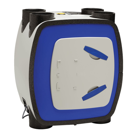
2. Product information The HRU ECO 4 consists of a central balanced ventilation unit with heat recovery, an installation kit and a condensate drain port. 2.1. Models HRU ECO 4 versions Item Type Description 7030000 HRU ECO 4 Apt Balanced ventilation unit with heat recovery;... -
Page 8: Technical Data
2.3. Technical data HRU ECO 4 Description Symbol Unit Apartment House DIMENSIONS AND WEIGHT Dimensions [HxWxD] — 848 x 730 x 479 Weight — CONNECTIONS Top duct connections — 4x Ø 150 inner / Ø 180 outer Bottom duct connections —... -
Page 9: Capacity
2.4. Capacity Pressure [Pa] Power [W] HRU ECO 4 Capacity [m Level 1 minimum Level 1 standard Level 1 maximum Mode 2 Level 3 minimum Level 3 standard Level 3 maximum Level 2 is a calculated value, depending on the set minimum and maximum capacity. -
Page 10: Dimension Drawings
2.5. Dimension drawings... -
Page 11: Parts
2.6. Parts Ventilation unit Rear bayonet ring Heat exchanger Front panel Front door Filter Motor module Connection cover with control board and power cable Insect filter Frost valve Bypass valve... -
Page 12: Controls
The aim of the summer bypass control is the ventilation of the dwelling with less heat transfer or none whatsoever. The Heatrae Sadia HRU ECO 4 heat recovery unit is supplied as standard with a bypass valve which is fully integrated into the unit. - Page 13 The controller of the ventilation unit uses a counter to keep track of The HRU ECO 4 has two filters, one for each air stream. Both filters when the filters need to be cleaned or replaced. If it detects that a...
- Page 14 2.7.4.2. Status LED The appliance is equipped with a status LED on the control panel. The status LED can display the following messages: Pattern Function Green Orange Blinks 1x/s Blinks 1x/s Identification Blinks 1x/s Pairing mode Lit 6 s Blinks 1x/s Frost mode Lit 5 s Blinks 2x/s...
-
Page 15: Installation
ä Caution! Always ensure that the ventilation unit is installed with the ducts To avoid noise complaints, Heatrae Sadia advises fitting connected to the correct air inlets and outlets. silencers at the connections of the two ducts coming from the dwelling. - Page 16 Mounting positions Standard high-rise Inverse high-rise Standard low-rise Inverse low-rise 1) See Converting before mounting. Exhaust air to outside Supply air from outside Supply air to dwelling D Exhaust air from dwelling Closed...
- Page 17 On the rear, turn the bayonet ring 90 degrees to the left (anti- clockwise) and remove it. The HRU ECO 4 heat recovery unit is supplied as standard with the motor module on the left side. If it fits better with the duct systems, the ventilation unit layout can be inverted easily without any tools before it is mounted on the wall.
- Page 18 e) Place the front door on the new front side as illustrated. Turn the front door 90 degrees to the right (clockwise) so it is nicely g) Fit both filter holders. vertical. Ensure that the circular foam gasket is present in the gap between the door and the heat exchanger.
-
Page 19: Wall Mounting
3.2.4. Wall mounting b) Fix the wall plate horizontally on the wall with five bolts (mounting hardware not included). a) Determine the exact location of the unit, taking the installation requirements into account. 5xø5mm c) Hook the mounting bracket over the wall plate to hang the Standard mounting. -
Page 20: Connecting The Condensate Drain
3.3. Connecting the condensate drain ä Caution! If the ventilation unit is situated outside the thermal shell of the dwelling (for example in a non-insulated attic), the condensate drain must be thermally insulated up to the ventilation unit. During winter, moisture in the exhaust air from the dwelling may condense in the heat exchanger. -
Page 21: Connecting The Ducts
3.4. Connecting the ducts 3.4.3. Supply air to dwelling ä Warning! When using the unit in multi-unit housing, it must be ensured at all times that there is no backflow into the dwelling from the central exhaust air duct. In this case, a mechanical check valve must be installed in the air outlet duct of the unit. -
Page 22: Electrical Connection
The ventilation unit and the CH boiler both need supply and exhaust ducts from and to the outside. The purpose of the coupler fitting is to simplify the duct systems of the HRU ECO 4 and the CH boiler. ä... -
Page 23: Operation
(or another level) in timer function. the morning. 3. Wired three-position switch for installation. A combination of the above options. You can pair a maximum of 20 wireless control switches and/or sensors with a Heatrae Sadia ventilation unit or system. -
Page 24: Sensors
4.3. Sensors The sensor is paired and the ventilation unit briefly changes speed to confirm the pairing. The ventilation unit is now ready to respond The ventilation unit can be controlled by the following available to the signals of the wireless sensor. sensors: RFT CO sensor;... -
Page 25: Commissioning
5. Commissioning 5.1. Preparation Note Before putting into service If a VKK coupling fitting or a heat pump is installed, the DIP The ventilation unit and accessories must be assembled. ● switch settings must be adjusted. For more information, see DIP The duct system must be assembled. -
Page 26: Adjusting The Capacity
5.3. Adjusting the capacity ä Caution! The capacities (high and low) of the ventilation unit must be set up during commissioning. Note If the capacity needs to be increased, first try opening the air valves more to see if this helps achieve the required capacity. Increasing the motor speed results in higher energy consumption and an increased noise level. -
Page 27: Setting The Supply/Exhaust Balance
ä Caution! Only adjust the potentiometer for high mode when the ventilation unit is loaded (connected to a duct system). If you adjust it when the ventilation unit is unloaded ("free discharge"), the current consumption may become too high. Current limiting on the circuit board will then cause irregular and jerky motor operation. -
Page 28: Inspection And Maintenance
6. Inspection and maintenance Proper functioning of the ventilation system, its capacity and its service life can only be assured if the system is inspected and maintained in accordance with the following instructions. These instructions are based on normal operating conditions. ä... -
Page 29: Inspecting, Cleaning And Replacing Filters
Fit the new filter in the filter holder. Note The HRU ECO 4 comes with G3 filters as standard. These filters are very suitable for use as "construction dust filters" after initial completion of the dwelling. After around three months, these filters should be replaced with G4 or F7 filters. -
Page 30: Resetting The Filter Indication
Any insects and other soiling in the filter will be removed by the vacuum cleaner. d) Replace the yellow cap. e) Put the HRU ECO 4 back into use by reinserting the plug into the power socket. 6.5. Replacing the frost valve motor The frost valve can be removed from the top of the appliance without tools and without any other actions. -
Page 31: Inspecting And Cleaning Air Valves
6.6. Inspecting and cleaning air valves c) Remove both filter holders. Check the air valves regularly (around once every three months) for soiling. If the air valves are dirty, they must be cleaned. ä Caution! When removing or replacing air valves and grilles, watch out for protruding duct sections. - Page 32 e) Remove the front panel. g) Remove the heat exchanger by grasping the clamp strip on the heat exchanger and pulling it out of the ventilation unit. This involves some friction. It is therefore necessary to restrain the housing so that the ventilation unit remains against the wall. Carry the heat exchanger by the clamp strip, not by the grey areas.
-
Page 33: Inspecting/Cleaning Ducts
Remove the insulation panel. o) Check whether the fan is still balanced by spinning one of the two impellers. If the impellers wobble significantly (and this is causing noise complaints), the entire motor module must be replaced. p) Assemble the motor module and the ventilation unit in the reverse order. -
Page 34: Service Parts
7. Service parts Exploded view... - Page 35 Order Item number Description quantity • • 95609505 Frost valve for HRU • • 95970205 HRU bypass valve • • 95607722 HRU fan • • 95607723 HRU-3 temperature sensor • • 95615088 BV (F)T vv I2C circuit board (HRU ECO 350) •...
-
Page 36: Faults
8. Faults The status LED on the ventilation unit blinks orange Cause Solution a) The ventilation unit detects that the filters Clean or replace the filters. For more ● need to be cleaned or replaced. information, see Inspecting, cleaning and replacing filters. - Page 37 The status LED on the ventilation unit blinks three times red and once orange Cause Solution a) The ventilation unit detects a fault with the Check whether the sensor is properly ● sensor. connected. Connect the sensor properly. Check the sensor for defects, and ●...
- Page 38 The supply fan (top) has stopped Cause Solution a) The fan connector is loose or not properly Fit the fan connector on the correct ● connected. connector on the circuit board. b) Frost control is active. If the outside temperature becomes very ●...
- Page 39 The fan runs at high speed when low speed is selected and at low speed when high speed or timer mode is selected Cause Solution a) One of the ventilation unit's internal Replace the faulty temperature sensor. ● temperature sensors is faulty. The fan suddenly starts running much faster or slower (for no apparent reason) Cause Solution...
- Page 40 The air quality in the dwelling is not good / air supply and extraction in the dwelling are not working properly Cause Solution a) One or both filters are dirty or blocked. Clean or replace dirty/blocked filters. ● b) The valves are dirty or blocked. Clean the valves.
-
Page 41: Warranty
9. Warranty HRU ECO 4 is supplied with a two-year parts and labour warranty, protecting the product against faulty manufacture and materials. The warranty period applies from the date of installation. Disclaimer This warranty does not apply to: Disassembly and assembly costs. -
Page 42: Declarations
EN 55014-1:2007/A1:2009 | EN 55014-1:2007/A2:2010 HRU ECO 4-Apartment EN 55014-2:1998 | EN 55014-2:1998/C1:1998 Ventilation unit with heat recovery EN 55014-2:1998/A1:2002 | EN 55014-2:1998/IS1:2007 HRU ECO 4 House EN 55014-2:1998/A2:2008 EN 61000-3-2:2006/A1:2009 | EN 61000-3-2:2006/A2:2009 ● EN 61000-3-3:2013 | EN 61000-6-1:2007... - Page 44 HEATRAE SADIA HEATING Hurricane Way, Norwich NR6 6EA www.heatraesadia.com SERVICE +44 (0)344 871 1535 EMAIL customer.support@heatraesadia.com 01-02502-002 | ID 2018-02-07-1424...
Need help?
Do you have a question about the HRU ECO 4 and is the answer not in the manual?
Questions and answers