Table of Contents
Advertisement
Quick Links
Advertisement
Table of Contents

Subscribe to Our Youtube Channel
Related Manuals for Edimax GS-5424PLC


Summary of Contents for Edimax GS-5424PLC
- Page 1 GS-5424PLC Switch User Manual 12-2017 / v1.0...
-
Page 2: Table Of Contents
CONTENTS Introduction ..................17 Overview ..................... 17 Package Content ..................17 Features ....................... 18 Product Components ................... 18 I-4-1 Ports ...................... 18 I-4-2 LED Indicators ..................19 II Installation ................... 20 II-1 Mounting the Switch ................... 20 II-1-1 Placement Tips..................20 II-1-2 Rack Mounting .................. - Page 3 IV-3-2 Long Range Mode ................. 48 IV-3-3 Error Disable ..................49 IV-3-4 Link Aggregation ................... 50 IV-3-4-1 Group ..................50 IV-3-4-2 Port Setting ................52 IV-3-4-3 LACP ..................54 IV-3-4-4 EEE ................... 56 IV-3-5 Jumbo Frame ..................57 IV-4 PoE ....................... 58 IV-4-1 Global Setting ..................
- Page 4 IV-8-1-5 Neighbor ................100 IV-8-1-6 Statistics ................104 IV-9 Multicast ....................107 IV-9-1 General ....................107 IV-9-1-1 Property................. 107 IV-9-1-2 Group Address ............... 108 IV-9-1-3 Router Port ................110 IV-9-2 IGMP Snooping ................... 112 IV-9-2-1 Property................. 112 IV-9-2-2 Querier .................. 115 IV-9-2-3 Statistics ................
- Page 5 IV-11-1 MAC ACL ..................166 IV-11-2 MAC ACE ..................167 IV-11-3 IPv4 ACL ..................169 IV-11-4 IPv4 ACE ..................170 IV-11-5 ACL Binding .................. 174 IV-12 QoS ......................176 IV-12-1 General ..................176 IV-12-1-1 Property................. 177 IV-12-1-2 Queue Scheduling..............180 IV-12-1-3 CoS Mapping .................
- Page 6 Safety and Regulatory Audience This guide is for the networking professional managing the standalone PG28CB switch series. It is recommended that only professionals with experience working with Intelligent Technology INC. networking devices who are familiar with the Ethernet and local area networking terminology, should service the equipment.
-
Page 7: I Introduction
Introduction Thank you for choosing a Edimax (PoE) WEB Smart Ethernet Switch. This device is designed to be operational right out-of-the-box as a standard bridge. In the default configuration, it will forward packets between connecting devices after powered up. Before you begin installing the switch, make sure you have all of the package contents available, and a PC with a web browser for using web-based system management tools. -
Page 8: Features
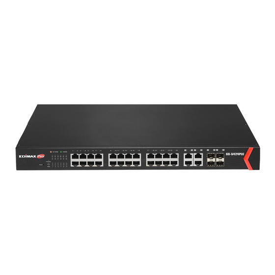
8K MAC address table and 10K jumbo frames 19-inch rack-mountable metal case Product Components I-4-1 Ports The following view applies to GS-5424PLC. Figure 1 - Front View No. Name Description Designed to connect to network devices with a bandwidth 10/100/1000Mbps of 10Mbps, 100Mbps or 1000Mbps. -
Page 9: I-4-2 Led Indicators
The following view applies to GS-5424PLC. Figure 2 - Rear View No. Name Description 1 AC power in Support AC100 – 240V 50-60Hz. I-4-2 LED Indicators The following view applies to GS-5424PLC. Figure 3 - Front View LED Indicators No. Name Description ... -
Page 10: Installation
Installation This chapter describes how to install and connect your Edimax Switch. Read the following topics and perform the procedures in the correct order. Incorrect installation may cause damage to the product. II-1 Mounting the Switch There are two ways to physically set up the switch. -
Page 11: Ii-1-2 Rack Mounting
II-1-2 Rack Mounting You can mount the switch in any standard size, 19-inch (about 48 cm) wide rack. The switch requires 1 rack unit (RU) of space, which is 1.75 inches (44.45 mm) high. For stability, load the rack from the bottom to the top, with the heaviest devices on the bottom. - Page 12 Secure the switch on the equipment rack with the screws provided. Figure 6 - Rack Installation...
-
Page 13: Getting Started
Getting Started This section provides an introduction to the web-based configuration utility, and covers the following topics: Powering on the device Connecting to the network Power over Ethernet (PoE) considerations Starting the web-based configuration utility III-1 Power III-1-1 Connecting to Power... -
Page 14: Iii-1-2 Connecting To Network
III-1-2 Connecting to Network To connect the switch to the network: Connect an Ethernet cable to the Ethernet port of a computer Connect the other end of the Ethernet cable to one of the numbered Ethernet ports of the switch. The LED of the port lights if the device connected is active. Repeat Step 1 and Step 2 for each device to connect to the switch. -
Page 15: Iii-1-3 Power Over Ethernet (Poe) Considerations
III-1-3 Power over Ethernet (PoE) Considerations For PoE switch models, consider the following information: Devices considered a Power Sourcing Equipment (PSE), can support up to 30 Watts per PoE port to a Powered Device (PD). Model Power Dedicated to PoE PoE Ports PoE Standard Supported GS-542PLC... -
Page 16: Iii-1-4 Starting The Web-Based Configuration Utility
III-1-4 Starting the Web-based Configuration Utility This section describes how to navigate the web-based switch configuration utility. Be sure to disable any pop-up blocker. Browser Restrictions If you are using older versions of Internet Explorer, you cannot directly use an IPv6 address to access the device. -
Page 17: Iii-1-5 Logging In
III-1-5 Logging In The default username is admin and the default password is admin. The first time that you log in with the default username and password, you are required to enter a new password. To log in to the device configuration utility: Enter the default user ID (admin) and the default password (admin). -
Page 18: Iii-1-6 Logging Out
please see the Launching the Configuration Utility section in the Administration Guide for additional information. III-1-6 Logging Out By default, the application logs out after ten minutes of inactivity. To manually logout, click Logout in the top right corner of any page. When a timeout occurs or you intentionally log out of the system, a message appears and the Login page appears, with a message indicating the logged-out state. -
Page 19: Web-Based Switch Configuration
Web-based Switch Configuration The PoE smart switch software provides rich Layer 2 functionality for switches in your networks. This chapter describes how to use the web-based management interface (Web UI) to configure the switch’s features. For the purposes of this manual, the user interface is separated into four sections, as shown in the following figure: Figure 11 - User Interface No. -
Page 20: Status
IV-1 Status Use the Status pages to view system information and status. IV-1-1 System Information This page shows switch panel, CPU utilization, Memory utilization and other system current information. It also allows user to edit some system information. display the Device Information web page, click Status > System Information. Figure 12 - Status >... - Page 21 System OID SNMP system object ID. System Uptime Total elapsed time from booting. Current Time Current system time. Loader Version Boot loader image version. Loader Date Boot loader image build date. Firmware Version Current running firmware image version. Firmware Date Current running firmware image build date.
-
Page 22: Iv-1-2 Logging Message
IV-1-2 Logging Message To view the logging messages stored on the RAM and Flash, click Status > Logging Message. Figure 14 - Status > Logging Message Item Description Log ID The log identifier. Time The time stamp for the logging message. Severity The severity for the logging message. -
Page 23: Iv-1-3 Port
IV-1-3 Port IV-1-3-1 Statistics This page displays standard counters on network traffic form the Interfaces, Ethernet -like and RMONMIB. Interfaces and Ethernet-like counters display errors on the traffic passing through each port. RMON counters provide a total count of different frame types and sizes passing through each port. - Page 25 Figure 15 - Status > Port > Statistics Item Description Port Select one port to show counter statistics. Select the MIB counter to show different counter type All: All counters. Interface: Interface related MIB counters. MIB Counter Etherlike: Ethernet-like related MIB counters. ...
-
Page 26: Error Disabled
IV-1-3-2 Error Disabled To display the Error Disabled web page, click Status > Port > Error Disabled. Figure 16 - Status > Port > Error Disabled Item Description □ Select one or more port to operate. Port Interface or port number. Port will be disabled by one of the following error reason: ... -
Page 27: Bandwidth Utilization
Port Security Violation DHCP rate limit ARP rate limit Time Left (sec) The time left in second for the error recovery. Refresh Refresh the current page. Recover Recover the selected port status. IV-1-3-3 Bandwidth Utilization This page allow user to browse ports’ bandwidth utilization in real time. This page will refresh automatically in every refresh period. -
Page 28: Iv-1-4 Link Aggregation
IV-1-4 Link Aggregation To display the Link Aggregation web page, click Status > Link Aggregation. Figure 18 - Status > Link Aggregation Item Description LAG Name. Name LAG port description. The type of the LAG. Static: The group of ports assigned to a static LAG are always active members. -
Page 29: Iv-1-5 Mac Address Table
IV-1-5 MAC Address Table The MAC address table page displays all MAC address entries on the switch including static MAC address created by administrator or auto learned from hardware. The “Clear” button will clear all dynamic entries and “Refresh” button will retrieve latest MAC address entries and show them on page. -
Page 30: Network
IV-2 Network Use the Network pages to configure settings for the switch network interface and how the switch connects to a remote server to get services. IV-2-1 IP Address This section allows you to edit the IP address, Netmask, Gateway and DNS server of the switch. - Page 31 Figure 20 - Network > IP Address Item Description The address type of switch IP configuration including Static: Static IP configured by users will be used. Address Type Dynamic: Enable the DHCP to obtain the IP address from a DHCP server.
- Page 32 default gateway must be in the same subnet with switch IP address configuration. DNS Server 1 Specify the primary user-defined IPv4 DNS server configuration. Specify the secondary user-defined IPv4 DNS server DNS Server 2 configuration. Table 3-2: IPv6 Address fields IPv4 Address The operational IPv4 address of the switch.
-
Page 33: Iv-2-2 System Time
IV-2-2 System Time This page allow user to set time source, static time, time zone and daylight saving settings. Time zone and daylight saving takes effect both static time or time from SNTP server. To display System Time page, click Network > System Time. Figure 21 - Network >... - Page 34 SNTP: Time sync from NTP server. From Computer: Time set from browser host. Manual Time: Time set by manually configure. Time Zone Select a time zone difference from listing district. SNTP Select the address type of NTP server. This is enabled when time Address Type source is SNTP.
-
Page 35: Port
IV-3 Port Use the Port pages to configure settings for switch port related features. IV-3-1 Port Setting This page shows port current status and allow user to edit port configura-tions. Select port entry and click “Edit” button to edit port configurations. To display Port Setting web page, click Port >... - Page 36 Port admin state Enabled: Enable the port. State Disabled: Disable the port. Current port link status Up: Port is link up. Link Status Down: Port is link down. Speed Current port speed configuration and link speed status. Duplex Current port duplex configuration and link duplex status.
- Page 37 Auto-100M: Auto speed with 100M ability only. Auto-1000M: Auto speed with 1000M ability only. Auto-10M/100M: Auto speed with 10M/100M abilities. 10M: Force speed with 10M ability. 100M: Force speed with 100M ability. 1000M: Force speed with 1000M ability. Port duplex capabilities.
-
Page 38: Iv-3-2 Long Range Mode
IV-3-2 Long Range Mode This page shows port current status and Enable long range mode will double the cabling distance but reduce the speed to 10Mbps. To display Long Range Mode web page, click Port > Long Range Mode Setting. Figure 24 - Port >... -
Page 39: Iv-3-3 Error Disable
IV-3-3 Error Disable To display Error Disabled web page, click Port > Error Disabled Figure 25 - Port > Error disable Item Description Recover Interval Auto recovery after this interval for error disabled port. Enabled to auto shutdown port when BPDU Guard reason occur. This BPDU Guard reason caused by STP BPDU Guard mechanism. -
Page 40: Iv-3-4 Link Aggregation
Enabled to auto shutdown port when ARP rate limit reason occur. ARP rate limit This reason caused by DHCP packet rate exceed ARP rate limit. IV-3-4 Link Aggregation IV-3-4-1 Group This page allow user to configure link aggregation group load balance algorithm and group member. - Page 41 Active Member Active member ports of the LAG. Inactive Member Inactive member ports of the LAG. Click “Edit” to edit Link Aggregation Group menu. Figure 27 - Port > Link Aggregation > Group > Edit Link Aggregation Group Item Description Selected LAG group ID.
-
Page 42: Iv-3-4-2 Port Setting
IV-3-4-2 Port Setting This page shows LAG port current status and allow user to edit LAG port configurations. Select LAG entry and click “Edit” button to edit LAG port configurations. To display LAG Port Setting web page, click Port > Link Aggregation > Port Setting. Figure 28 - Port >... - Page 43 Click “Edit” to view Edit Port Setting menu. Figure 29 - Port > Link Aggregation > Port Setting > Edit Port Setting Item Description Port Selected Port list. Description Port description. Port admin state Enabled: Enable the port. State ...
-
Page 44: Iv-3-4-3 Lacp
IV-3-4-3 LACP This page allow user to configure LACP global and port configurations. Select ports and click “Edit” button to edit port configuration. To display the LACP Setting web page , click Port > Link Aggregation > LACP. Figure 30 - Port > Link Aggregation > LACP Item Description Configure the system priority of LACP. - Page 45 Click "Edit" button to view Edit LACP Port Setting menu. Figure 31 - Port > Link Aggregation > LACP > Edit LACP Port Setting Item Description Port Selected port list. Port Priority Enter the LACP priority value of the port The periodic transmissions type of LACP PDUs.
-
Page 46: Iv-3-4-4 Eee
IV-3-4-4 This page allow user to configure Energy Efficient Ethernet settings. To display the EEE web page, click Port > EEE. Figure 32 - Port > EEE Item Description Port Port Name. Port EEE admin state Enabled: EEE is enabled. State ... -
Page 47: Iv-3-5 Jumbo Frame
Click “Edit” to edit the EEE menu. Figure 33 - Port > EEE > Edit EEE Setting Item Description Port Port Name Port EEE admin state Enabled: EEE is enabled. State Disabled: EEE is disabled. IV-3-5 Jumbo Frame This page allow user to configure switch jumbo frame size. -
Page 48: Poe
IV-4 Port security can set port isolation and specific behavior. IV-4-1 Global Setting To display the Global web page, click PoE > Global Setting. Figure 35 - PoE > Global Setting... - Page 49 Item Description Nominal Power Maximum supply power. Consuming Power Current consumed power. Remaining Power Remaining available power. Schedule Status Schedule status global switch. Name PoE Schedule Name. Port List The ports provide power in designated schedule index. Schedule Status The current schedule status. Click “Edit”...
-
Page 50: Iv-4-2 Priority Setting
IV-4-2 Priority Setting Use this section to set the power supply priority of PoE ports. Individual ports can be assigned critical, high, or low power supply priority. To display the Priority Setting web page, click PoE > Priority Setting. Figure 37 - PoE > Priority Setting Click the port to change its priority status according to the bottom right hand chart. -
Page 51: Iv-4-3 Power Limit
IV-4-3 Power Limit To display the Power Limit web page, click PoE > Power Limit. Figure 38 - PoE > Power Limit Item Description Port Port name. Power Limit The max supply power for this port. - Page 52 Click “Edit” to view Power Limit Setting menu. Figure 39 - PoE > Power Setting > Power Limit Setting Table Item Description Port List Selected port list. Power Limit Enter max supply power value for the selected port list.
-
Page 53: Iv-4-4 Poe Status
IV-4-4 PoE Status To display the PoE Status web page, click PoE > Power Status. Figure 40 - PoE > Power Stauts Per Port PoE Status Checked: Port PoE status is enabled. Unchecked: Port PoE status is disabled. -
Page 54: Vlan
IV-5 VLAN A virtual local area network, virtual LAN or VLAN, is a group of hosts with a common set of requirements that communicate as if they were attached to the same broadcast domain, regardless of their physical location. A VLAN has the same attributes as a physical local area network (LAN), but it allows for end stations to be grouped togeth-er even if they are not located on the same network switch. - Page 55 VLAN had been created. Created VLAN Select created VLANs from right box then move to left box to delete VLAN The VLAN ID. Name The VLAN Name. The VLAN Type. Static: Port base VLAN. Type Dynamic: 802.1q VLAN. Click “Edit”...
-
Page 56: Vlan Configuration
IV-5-1-2 VLAN Configuration This page allow user to configure the membership for each port of selected VLAN. To display VLAN Configuration page, click VLAN > VLAN > VLAN Configuration. Figure 43 - VLAN > VLAN > VLAN Configuration Item Description VLAN Select specified VLAN ID to configure VLAN configuration. -
Page 57: Iv-5-1-3 Membership
Excluded: Specify the port is excluded in the VLAN. Tagged: Specify the port is tagged member in the VLAN. Untagged: Specify the port is untagged member in the VLAN. PVID Display if it is PVID of interface. IV-5-1-3 Membership This page allow user to view membership information for each port and edit membership... - Page 58 Item Description Port Display the interface of port entry. Mode Display the interface VLAN mode of port. Administrative Display the administrative VLAN list of this port. VLAN Display the operational VLAN list of this port. Operational VLAN means Operational the VLAN status that really runs in device. It may different to VLAN administrative VLAN.
-
Page 59: Iv-5-1-4 Port Setting
VLAN ID for this port. PVID may auto select or can’t select in differ settings. IV-5-1-4 Port Setting This page allow user to configure ports VLAN settings such as VLAN port mode, PVID etc…The attributes depend on different VLAN port mode. To display Port Setting page, click VLAN >... - Page 60 Item Description Port Display the interface. Mode Display the VLAN mode of interface. PVID Display the Port-based VLAN ID of port. Accept Frame Type Display accept frame type of port. Ingress Filtering Display ingress filter status of port. Uplink Display uplink status. TPID Display TPID used of interface.
- Page 61 Filtering Hybrid mode. Set checkbox to enable/disable uplink mode. It’s only available with trunk Uplink mode. TPID Select TPID used of interface. It’s only available with trunk mode.
-
Page 62: Iv-5-2 Voice Vlan
IV-5-2 Voice VLAN Use the Voice VLAN pages to configure settings of Voice VLAN. IV-5-2-1 Property This page allow user to configure global and per interface settings of voice VLAN. To display Property Web page, click VLAN> Voice VLAN> Property. Figure 48 - VLAN >... - Page 63 Item Description State Set checkbox to enable or disable voice VLAN function. VLAN Select Voice VLAN ID. Voice VLAN ID cannot be default VLAN. Select a value of VPT. Qualified packets will use this VPT value as inner Cos/802.1p priority. Set checkbox to enable or disable 1p remarking.
-
Page 64: Iv-5-2-2 Voice Oui
IV-5-2-2 Voice OUI This page allow user to add, edit or delete OUI MAC addresses. Default has 8 pre-defined OUI MAC. To display the Voice OUI Web page, click VLAN > Voice VLAN > Voice OUI. Figure 50 - VLAN > Voice VLAN > Voice OUI Item Description Display OUI MAC address. -
Page 65: Iv-5-3 Mac Vlan
Item Description Input OUI MAC address. Can’t be edited in edit dialog. Input description of the specified MAC address to the voice VLAN Description OUI table. IV-5-3 MAC VLAN Use the MAC VLAN pages to configure settings of MAC VLAN. IV-5-3-1 MAC Group This page allow user to add or edit groups settings of MAC VLAN. -
Page 66: Iv-5-3-2 Group Binding
Figure 53 - VLAN > MAC VLAN > MAC Group > Add/Edit MAC Item Description Input group ID that is a unique ID of mac group entry. The range Group ID from 1 to 2147483647. Only available on Add Dialog. MAC Address Input mac address for classifying packets. - Page 67 Item Description Port Display port ID that binding with MAC group entry. Group ID Display group ID that port binding with. VLAN Display VLAN ID that assign to packets which match MAC group. Click “Add” or “Edit” button to view the Add/Edit Group Binding menu. Figure 55 - VLAN >...
-
Page 68: Mac Address Table
IV-6 MAC Address Table Use the MAC Address Table pages to show dynamic MAC table and configure settings for static MAC entries. IV-6-1 Dynamic Address To display the Dynamic Address web page, click MAC Address Table > Dynamic Address. Figure 56 - MAC Address Table > Dynamic Address Item Description The time in seconds that an entry remains in the MAC address... -
Page 69: Iv-6-3 Filtering Address
Item Description MAC Address The MAC address to which packets will be statically forwarded. VLAN Specify the VLAN to show or clear MAC entries. Port Interface or port number. IV-6-3 Filtering Address To display the Filtering Address web page, click MAC Address Table > Filtering Address. Figure 58 - MAC Address Table >... -
Page 70: Spanning Tree
IV-7 Spanning Tree The Spanning Tree Protocol (STP) is a network protocol that ensures a loop-free topology for any bridged Ethernet local area network. IV-7-1 Property To display the Property web page, click Spanning Tree > Property. Figure 59 - Spanning Tree > Property... - Page 71 Item Description State Enable/disable the STP on the switch. Specify the STP operation mode. STP: Enable the Spanning Tree (STP) operation. Operation Mode RSTP: Enable the Rapid Spanning Tree (RSTP) operation. MSTP: Enable the Multiple Spanning Tree (MSTP) operation. Specify the path cost method.
-
Page 72: Iv-7-2 Port Setting
Last Topology The last time for the topology change. Change IV-7-2 Port Setting To configure and display the STP port settings, click STP > Port Setting. Figure 60 - Spanning Tree > Port Setting Item Description Port Specify the interface ID or the list of interface IDs. State The operational state on the specified port. - Page 73 Designated Port The designated port ID on the switch. Designated Cost The path cost of the designated port on the switch. Protocol Restart the Spanning Tree Protocol (STP) migration process Migration Check (re-negotiate with its neighborhood) on the specific interface. Click "Edit"...
-
Page 74: Iv-7-3 Mst Instance
In the edge mode, the interface would be put into the Forwarding state immediately upon link up. If the edge mode is enabled for the interface and there are BPDUs received on the interface, the loop might be occurred in the short time before the STP state change. - Page 75 Item Description MSTI Designated port number. Priority The bridge priority on the specified MSTI. Bridge Identifier The bridge identifier on the specified MSTI. Designated Root Bridge The designated root bridge identifier on the specified MSTI. Root Port The designated root port on the specified MSTI. Root Path Cost The designated root path cost on the specified MSTI.
-
Page 76: Iv-7-4 Mst Port Setting
IV-7-4 MST Port Setting To configure and display MST port setting, click STP > MST Port Setting. Figure 64 - Spanning Tree > MST Port Setting Item Description MSTI Specify the port setting on the specified MSTI. Port Specify the interface ID or the list of interface IDs. Path Cost The port path cost on the specified MSTI. - Page 77 Internal: The port attaching an MST Bridge to a LAN that is not in the same region. Designated The bridge ID of the designated bridge. Bridge Designated Port The designated port ID on the switch. Designated Cost The path cost of the designated port on the switch. Remaining Hop The remaining hops count on the specified port.
-
Page 78: Iv-7-5 Statistics
IV-7-5 Statistics To display the STP statistics, click STP > Statistics. Figure 66 - Spanning Tree > Statistics Item Description Refresh Rate The option to refresh the statistics automatically. Receive BPDU (Config) The counts of the received CONFIG BPDU. Receive BPDU (TCN) The counts of the received TCN BPDU. - Page 79 Click "View" button to view the STP Port Statistic menu. Figure 67 - Spanning Tree > Statistics > STP Port Statistic Item Description Refresh Rate The option to refresh the statistics automatically. Clear Clear the statistics for the selected interfaces.
-
Page 80: Discovery
IV-8 Discovery Use this section to configure LLDP. IV-8-1 LLDP LLDP is a one-way protocol; there are no request/response sequences. Informa-tion is advertised by stations implementing the transmit function, and is received and processed by stations implementing the receive function. The LLDP category contains LLDP and LLDP-MED pages. - Page 81 Interval seconds, and the valid range is 5–32767 seconds. Holdtime Select the multiplier on the transmit interval to assign to TTL (range Multiplier 2–10, default = 4). Reinitialization Select the delay before a re-initialization (range 1–10 seconds, default Delay = 2). Select the delay after an LLDP frame is sent (range 1–8191 seconds, Transmit Delay default = 3).
-
Page 82: Iv-8-1-2 Port Setting
IV-8-1-2 Port Setting To display LLDP Port Setting, click Discovery > LLDP > Port Setting. Figure 69 - Discovery > LLDP > Port Setting Item Description Port Port Name. Mode The port LLDP mode. Selectde TLV The Selected LLDP TLV. - Page 83 Click "Edit" button to view Edit Port Setting menu. Figure 70 - Discovery > LLDP > Port Setting > Edit Port Setting Item Description Port Select specified port or all ports to configure LLDP state. Select the transmission state of LLDP port interface. ...
-
Page 84: Iv-8-1-3 Packet View
802.1 VLAN Select the VLAN Name ID to be carried (multiple selection is Name allowed). IV-8-1-3 Packet View To display LLDP Overloading, click Discovery > LLDP > Packet View. Figure 71 - Discovery > LLDP > Packet View... - Page 85 Item Description Port Port Name. In-Use (Bytes) Total number of bytes of LLDP information in each packet. Total number of available bytes left for additional LLDP information Available (Bytes) in each packet. Operational Status Overloading or not. Click "Detail" button to view Packet View Detail menu.
- Page 86 Figure 72 - Discovery > LLDP > Packet View > Packet View Detail Item Description Port Port Name. Mandatory TLVs Total mandatory TLV byte size. Status is sent or overloading. Total MED Capabilities TLV byte size. Status is sent or MED Capabilities overloading.
-
Page 87: Iv-8-1-4 Local Information
IV-8-1-4 Local Information Use the LLDP Local Information to view LLDP local device information. To display LLDP Local Device, click Discovery > LLDP > Local Information. - Page 88 Figure 73 - Discovery > LLDP > Local Information Item Description Chassis ID Subtype Type of chassis ID, such as the MAC address. Identifier of chassis. Where the chassis ID subtype is a MAC address, Chassis ID the MAC address of the switch is displayed. System Name Name of switch.
- Page 89 Supported Capabilities Primary enabled functions of the device. Enabled Port ID Subtype Type of the port identifier that is shown. LLDP Status LLDP Tx and Rx abilities. LLDP Med Status LLDP MED enable state. Click “Detail” button on the page to view detail information of the selected port.
-
Page 90: Iv-8-1-5 Neighbor
Figure 74 - Discovery > LLDP > Local Information > Detail IV-8-1-5 Neighbor Use the LLDP Neighbor page to view LLDP neighbors information. To display LLDP Remote Device, click Discovery > LLDP > Neighbor. Figure 75 - Discovery > LLDP > Neighbor... - Page 91 Item Description Local Port Number of the local port to which the neighbor is connected. Chassis ID Subtype Type of chassis ID (for example, MAC address). Port ID Subtype Type of the port identifier that is shown. Port ID Identifier of port. System Name Published name of the switch.
- Page 92 Click “detail” to view selected neighbor detail information...
- Page 93 Figure 76 LLDP Neighbor Detail Page...
-
Page 94: Iv-8-1-6 Statistics
IV-8-1-6 Statistics The Link Layer Discovery Protocol (LLDP) Statistics page displays summary and per-port information for LLDP frames transmitted and received on the switch. - Page 95 To display LLDP Statistics status, click Discovery > LLDP > Statistics. Figure 77 - Discovery > LLDP > Statistics...
- Page 96 Item Description The number of times the complete set of information advertised by a Insertions particular MAC Service Access Point (MSAP) has been inserted into tables associated with the remote systems. The number of times the complete set of information advertised by Deletions MSAP has been deleted from tables associated with the remote systems.
-
Page 97: Multicast
IV-9 Multicast Use this section to configure Multicast. IV-9-1 General Use the General pages to configure settings of IGMP and MLD common function. IV-9-1-1 Property To display multicast general property Setting web page, click Multicast> General> Property. Figure 78 - Multicast > General > Property Item Description Set the unknown multicast action... -
Page 98: Iv-9-1-2 Group Address
IV-9-1-2 Group Address This page allow user to browse all multicast groups that dynamic learned or statically added. To display Multicast General Group web page, click Multicast> General > Group Address. Figure 79 - Multicast > General > Group Address Item Description IP Version... - Page 99 Click “Add” or “Edit” button to view Add or Edit Group Address menu. Figure 80 - Multicast > General > Group Address > Add/Edit Group Address Item Description VLAN The VLAN ID of group. IP Version IPv4: ipv4 multicast group IP Version ...
-
Page 100: Iv-9-1-3 Router Port
Available Port: Optional port member Selected Port: Selected port member IV-9-1-3 Router Port This page allow user to browse all router port information. The static and forbidden router port can set by user. To display multicast router port table web page, click Multicast > General > Router Port. Figure 81 - Multicast >... - Page 101 Click "Add" or “Edit” button to view Add/Edit Router Port menu. Figure 82 - Multicast > General > Router Port > Add/Edit Router Port...
-
Page 102: Iv-9-2 Igmp Snooping
Item Description The VLAN ID for router entry Available VLAN: Optional VLAN member VLAN Selected VLAN: Selected VLAN member. IP Version IPv4: ipv4 multicast router IP Version IPv6: ipv6 multicast router The router port type Static: static router port Type ... - Page 103 Item Description Set the enabling status of IGMP Snooping functionality State Enable: If Checked Enable IGMP Snooping, else is Disabled IGMP Snooping. Set the igmp snooping version IGMPv2: Only support process igmp v2 packet. Version IGMPv3: Support v3 basic and v2. Set the enabling status of IGMP v2 report suppression Report Suppression Enable: If Checked Enable IGMP Snooping v2 report suppression,...
- Page 104 Click "Edit" button to Edit VLAN Setting menu. Figure 84 - Multicast > IGMP Snooping > Property >Edit VLAN Setting Item Description VLAN The selected VLAN List. Set the enabling status of IGMP Snooping VLAN functionality State Enable: If Checked Enable IGMP Snooping VLAN, else is Disabled IGMP Snooping VLAN.
-
Page 105: Iv-9-2-2 Querier
Query Interval The Admin interval of querier to send general query. The Admin query max response interval, In Membership Query Query Max Messages, it specifies the maximum allowed time before sending a Response Interval responding report in units of 1/10 second. The Admin last member query count that Querier-switch sends Last Member Group-Specific Queries when it receives a Leave Group message for a... - Page 106 Item Description VLAN IGMP Snooping querier entry VLAN ID. State The IGMP Snooping querier Admin State. Operational Status The IGMP Snooping querier operational status. Querier Version The IGMP Snooping querier operational version. Querier IP The operational Querier IP address on the VLAN. Click "Edit"...
-
Page 107: Iv-9-2-3 Statistics
IV-9-2-3 Statistics This page allow user to clear igmp snooping statics. To display IGMP Snooping Statistics, click Multicast > IGMP Snooping > Statistics. Figure 87 - Multicast > IGMP Snooping > Statistics Item Description Receive Packet Total Total RX igmp packet, include ipv4 multicast data to CPU. Valid The valid igmp snooping process packet. - Page 108 Group Query Transmit Packet Leave IGMP leave packet Report IGMP join and report packet IGMP general query packet include querier transmit general query General Query packet. Special Group IGMP special group query packet include querier transmit special Query group query packet. Source-specific IGMP Special Source and Group General Query packet.
-
Page 109: Iv-9-3 Mvr
IV-9-3 Use the MVR pages to configure settings of MVR function. IV-9-3-1 Property To display multicast MVR property Setting web page, click Multicast > MVR > Property. Figure 88 - Multicast > MVR > Property Item Description State Enable: if checked enable the MVR state, else disable the MVR state. VLAN The MVR VLAN ID. -
Page 110: Iv-9-3-2 Port Setting
IV-9-3-2 Port Setting This page allow user to configure port role and port immediate leave. To display MVR port role and immediate leave state setting web page, click Multicast > MVR > Port Setting. Figure 89 - Multicast > MVR > Port Setting... - Page 111 Item Description Entry Entry of number. Port Port Name. Role Port Role for MVR, the type is None/Receiver/Source. Immediate Leave Status of immediate leave. Click "Edit" button to view Edit Port Setting menu. Figure 90 - Multicast > MVR > Port Setting > Edit Port Setting Item Description Port...
-
Page 112: Iv-9-3-3 Group Address
IV-9-3-3 Group Address This page allow user to browse all multicast MVR groups that dynamic learned or statically added. To display Multicast MVR Group web page, click Multicast > MVR > Group Address. Figure 91 - Multicast > MVR > Group Address Item Description VLAN... - Page 113 Item Description VLAN The VLAN ID of MVR group. Group Address The MVR group IP address. The member ports of MVR group. Available Port: Optional port member, it is only receiver port when Member MVR mode is compatible, it include source port when mode is dynamic.
-
Page 114: Iv-10 Security
IV-10 Security Use the Security pages to configure settings for the switch security features. IV-10-1 RADIUS This page allow user to add, edit or delete RADIUS server settings and modify default parameter of RADIUS server. To display RADIUS web page, click Security > RADIUS. Figure 93 - Security >... - Page 115 keep trying until timeout. RADIUS server usage type Login: For login authentifation. Usage 802.1x: For 802.1x authentication. All: For all types. Click "Add" or “Edit” button to view Add/Edit RADIUS Server menu.
- Page 116 Figure 94 - Security > RADIUS > Add/Edit RADIUS Server Item Description In add dialog, user need to specify server Address Type Hostname: Use domain name as server address. Address Type IPv4: Use IPv4 as server address. IPv6: Use IPv6 as server address. In add dialog, user need to input server address based on Server Address address type.
-
Page 117: Iv-10-2 Management Access
IV-10-2 Management Access Use the Management Access pages to configure settings of management access. IV-10-2-1 Management Service This page allow user to change management services related configurations. To display Management Service click Security > Management Access > Management Service. Figure 95 - Security > Management Access > Management Service... -
Page 118: Iv-10-2-2 Management Acl
Item Description Management service admin state. Telnet: Connect CLI through telnet. SSH: Connect CLI through SSH. Management HTTP: Connect WEBUI through HTTP. Service HTTPS: Connect WEBUI through HTTPS. SNMP: Manage switch trough SNMP. Set session timeout minutes for user access to user interface. 0 minutes Session Timeout means never timeout. -
Page 119: Iv-10-2-3 Management Ace
Rule Display the number Management ACE rule of ACL. IV-10-2-3 Management ACE This page allow user to add, edit or delete ACE rule. An ACE rule cannot be edited or deleted if ACL under active. New ACE cannot be added if ACL under active To display Management ACE page, click Security >... - Page 120 Click "Add" or “Edit” button to view Add/Edit Management ACE menu.
- Page 121 Figure 98 - Security > Management Access > Add/Edit Management ACE Item Description ACL Name Display the ACL name to which an ACE is being added. Specify the priority of the ACE. ACEs with higher sequence are processed Priority first (1 is the highest priority). Only available on Add Dialog. Select the type service of rule.
- Page 122 Deny: Drop packets that meet the ACE criteria. Port Select ports which will be matched. Select the type of source IP address. All: All IP addresses can access. IP Version IPv4: Specify IPv4 address ca access. IPv6: Specify IPv6 address ca access. IPv4 Enter the source IPv4 address value and mask to which will be matched.
-
Page 123: Iv-10-3 Authentication Manager
IV-10-3 Authentication Manager IV-10-3-1 Property This page allow user to edit authentication global settings and some port mods’ configurations. To display authentication manager Property web page, click Security > Authentication Manager > Property. Figure 99 - Security > Authentication Manager > Property Item Description Set checkbox to enable/disable following authentication types... - Page 124 authentication Set checkbox to enable/disable guest VLAN, if guest VLAN is enabled, Guest VLAN you need to select one available VLAN ID to be guest VID. Select mac-based authentication RADIUS username/password ID format. XXXXXXXXXXXX Xxxxxxxxxxxx XX:XX:XX:XX:XX:XX xx:xx:xx:xx:xx:xx ...
- Page 125 Support following authentication type order combinations. Web Authentication should always be the last type. The authentication manager will go to next type if current type is not enabled or authenticated fail. 802.1x MAC-Based WEB-Based Order 802.1x MAC-Based ...
- Page 126 Click “Edit” button to view the Edit Port Mode menu. Figure 100 - Security > Authentication Manager > Property > Edit Port Mode Item Description Port Selected port list. Authentication Type Set checkbox to enable/disable authentication types. Select authenticating host mode ...
- Page 127 Support following authentication type order combinations. Web Authentication should always be the last type. The authentication manager will go to next type if current type is not enabled or authenticated fail. 802.1x MAC-Based WEB-Based Order 802.1x MAC-Based ...
-
Page 128: Iv-10-3-2 Port Setting
IV-10-3-2 Port Setting This page allow user to configure authentication manger port settings To display the authentication manager Port Setting web page, click Security > Authentication Manager > Port Setting. Figure 101 - Security > Authentication Manager > Port Setting Item Description Port... - Page 129 In Multiple Authentication mode, total host number cannot not Max Hosts exceed max hosts number. Common Timer After re-authenticate period, host will return to initial state and need (Reauthentication) to pass authentication procedure again. If no packet from the authenticated host, the inactive timer will Common Timer increase.
- Page 130 Click "Edit" button to view Edit Port Setting menu. Figure 102 - Security > Authentication Manager > Port Setting > Edit Port Setting Item Description Port Port Name. Support following authentication port control types. Disable: Disable authentication function and all clients have network accessibility.Force Authorized: Port is force authorized and all clients have network accessibility.
-
Page 131: Iv-10-3-3 Sessions
In Multiple Authentication mode, total host number cannot not Max Hosts exceed max hosts number. Common Timer After re-authenticate period, host will return to initial state and need Reauthentication to pass authentication procedure again. If no packet from the authenticated host, the inactive timer will increase. - Page 132 Item Description Session ID Session ID is unique of each session. Port Port name which the host located. MAC Address Host MAC address. Show current authenticating type 802.1x: Use IEEE 802.1X to do authenticating MAC-Based: Use MAC-Based authentication to do Current Type authenticating.
-
Page 133: Iv-10-4 Port Security
IV-10-4 Port Security This page allow user to configure port security settings for each interface. When port security is enabled on interface, action will be perform once learned MAC address over limitation. To display Port Security web page, click Security > Port Security. Figure 104 - Security >... - Page 134 Item Description State Enable/Disable the port security function. Port Select one or multiple ports to configure. Select the status of port security Disable: Disable port security function. State Enable: Enable port security function. MAC Address Specify the number of how many mac addresses can be learned. Select the action if learned mac addresses ...
-
Page 135: Iv-10-5 Protected Port
IV-10-5 Protected Port This page allow user to configure protected port setting to prevent the selected ports from communication with each other. Protected port is only allowed to communicate with unprotected port. In other words, protected port is not allowed to communicate with another protected port. - Page 136 Item Description Port Port Name. Port protected admin state. Protected: Port is protected. State Unprotected: Port is unprotected Click "Edit" button to view Edit Protected Port menu. Figure 107 - Security > Protected Port > Edit Protected Port Item Description Port...
-
Page 137: Iv-10-6 Storm Control
IV-10-6 Storm Control To display Storm Control global setting web page, click Security > Storm Control. Figure 108 - Security > Storm Control Item Description Select the unit of storm control Packet / Sec: storm control rate calculates by packet-based Mode(Unit) ... - Page 138 Included: include preamble & IFG (20 bytes) when count ingress storm control rate. Click "Edit" button to view Edit Port Setting menu. Figure 109 - Security > Storm Control > Edit Port Setting Item Description Port Select the setting ports. Select the state of setting State Enable: Enable the storm control function.
-
Page 139: Iv-10-7 Dos
control rate. IV-10-7 A Denial of Service (DoS) attack is a hacker attempt to make a device unavailable to its users. DoS attacks saturate the device with external communication requests, so that it cannot respond to legitimate traffic. These attacks usually lead to a device CPU overload. The DoS protection feature is a set of predefined rules that protect the network from malicious attacks. -
Page 140: Iv-10-7-1 Property
IV-10-7-1 Property To display Dos Global Setting web page, click Security > Dos > Property. Figure 110 - Security > DoS > Property Item Description Avoids ping of death attack. Drops the packets if the source IP address is equal to the destination Land IP address. - Page 141 destination port. Drops the packages if the TCP source port is equal to the TCP TCP Blat destination port. Drops the packets if the destination MAC address is equal to the DMAC = SMAC source MAC address. Null Scan Attach Drops the packets with NULL scan.
-
Page 142: Iv-10-7-2 Port Setting
IV-10-7-2 Port Setting To configure and display the state of DoS protection for interfaces, click Security > DoS > Port Setting. Figure 111 - Security > DoS > Port Setting Item Description Port Interface or port number. State Enable/Disable the DoS protection on the interface. -
Page 143: Iv-10-8 Dhcp Snooping
IV-10-8 DHCP Snooping Use the DHCP Snooping pages to configure settings of DHCP Snooping. IV-10-8-1 Property This page allow user to configure global and per interface settings of DHCP Snooping. To display property page, click Security > DHCP Snooping > Property. Figure 112 - Security >... - Page 144 Item Description State Set checkbox to enable/disable DHCP Snooping function. Select VLANs in left box then move to right to enable DHCP VLAN Snooping. Or select VLANs in right box then move to left to disable DHCP Snooping. Port Setting Table Port Display port ID.
-
Page 145: Iv-10-8-2 Statistics
IV-10-8-2 Statistics This page allow user to browse all statistics that recorded by DHCP snooping function. To view the Statistics menu, navigate to Security > DHCP Snooping > Statistics. Figure 114 - Security > DHCP Snooping > Statistics Item Description Port Display port ID. - Page 146 Chaddr Check Drop Display how many packets dropped by chaddr validation. Untrusted Port Display how many DHCP server packets that are received by Drop untrusted port dropped. Untrusted Port Display how many packets dropped by untrusted port with option82 with Option82 checking.
-
Page 147: Iv-10-8-3 Option82 Property
IV-10-8-3 Option82 Property This page allow user to set string of DHCP option82 remote ID filed. The string will attach in option82 if option inserted. To display Option82 Property page, click Security > DHCP Snooping > Option82 Property. Figure 115 - Security > DHCP Snooping > Option82 Property Item Description Set checkbox to enable user-defined remote-ID. - Page 148 Input user-defined remote ID. Only available when enable user-define Remote ID remote ID. Port Setting Table Port Display port ID. State Display option82 enable/disable status of interface. Allow untrusted Display allow untrusted action of interface. Click "Edit" button to view Edit Port Setting menu. Figure 116 DHCP Snooping >...
-
Page 149: Option82 Circuit Id
IV-10-8-4 Option82 Circuit ID This page allow user to set string of DHCP option82 circuit ID filed. The string will attach in option82 if option inserted. To display Option82 Circuit ID page, click Security > DHCP Snooping > Option82 Circuit Figure 117 - Security >... - Page 150 Item Description Select port from list to associate to CID entry. Only available on Add Port dialog. Input VLAN ID to associate to circuit ID entry. VLAN ID is not mandatory. VLAN Only available on Add dialog. Input String as circuit ID. Packets match port and VLAN will be inserted Circuit ID circuit ID.
-
Page 151: Iv-10-9 Ip Source Guard
IV-10-9 IP Source Guard Use the IP Source Guard pages to configure settings of IP Source Guard. IV-10-9-1 Port Setting Use the IP Source Guard pages to configure settings of IP Source Guard. To display Port Setting page, click Security > IP Source Guard > Port Setting. Figure 119 - Security >... - Page 152 Item Description Port Display port ID. State Display IP Source Guard enable/disable status of interface. Verify Source Display mode of IP Source Guard verification Current Binding Entry Display current binding entries of a interface. Max Binding Entry Display the number of maximum binding entry of interface. Click "Edit"...
-
Page 153: Iv-10-9-2 Impv Binding
IV-10-9-2 IMPV Binding This page allow user to add static IP source guard entry and browse all IP source guard entries that learned by DHCP snooping or statically create by user. To display IPMV Binding page, click Security > IP Source Guard > IMPV Binding. Figure 121 - Security >... - Page 154 Click "Add" or “Edit” button to view the Add/Edit IP-MAC-Port-VLAN Binding menu. Figure 122 - Security > IP Source Guard > Add/Edit IP-MAC-Port-VLAN Binding Item Description Port Select port from list of a binding entry. VLAN Specify a VLAN ID of a binding entry. Select matching mode of binding entry IP-MAC-Port-VLAN: packet must match IP address、MAC address、...
-
Page 155: Iv-10-9-3 Save Database
IV-10-9-3 Save Database This page allow user to configure DHCP snooping database which can backup and restore dynamic DHCP snooping entries. To display Save Database page, click Security > DHCP Snooping > Save Database. Figure 123 - Security > IP Source Guard > Save Database Item Description Select the type of database agent. -
Page 156: Iv-11 Acl
IV-11 ACL Use the ACL pages to configure settings for the switch ACL features.. IV-11-1 MAC ACL This page allow user to add or delete ACL rule. A rule cannot be deleted if under binding. To display MAC ACL page, click ACL > MAC ACL. Figure 124 - ACL >... -
Page 157: Iv-11-2 Mac Ace
IV-11-2 MAC ACE This page allow user to add, edit or delete ACE rule. An ACE rule cannot be edited or deleted if ACL under binding. New ACE cannot be added if ACL under binding. To display MAC ACE page, click ACL > MAC ACE. Figure 125 - ACL >... - Page 158 Click “Edit” button to view the Edit ACE menu. Figure 126 - ACL > Edit ACE Item Description ACL Name Display the ACL name to which an ACE is being added.. Specify the sequence of the ACE. ACEs with higher sequence are Sequence processed first (1 is the highest priority).
-
Page 159: Iv-11-3 Ipv4 Acl
Any: All destination addresses are acceptable. User Defined: Only a destination address or a range of destination addresses which users define are acceptable. Enter the destination MAC address and mask to which will be matched. Select the type for Ethernet frame type. ... -
Page 160: Iv-11-4 Ipv4 Ace
Item Description ACL Name Input IPv4 ACL name. ACL Name Display IPv4 ACL name. Rule Display the number ACE rule of ACL. Port Display the port list that bind this ACL. IV-11-4 IPv4 ACE This page allow user to add, edit or delete ACE rule. An ACE rule cannot be edited or deleted if ACL under binding. - Page 161 Click "Add" or “Edit” button to view the Add/Edit ACE menu. Figure 129 - ACL > Add/Edit ACE...
- Page 162 Item Description ACL Name Display the ACL name to which an ACE is being added. Specify the sequence of the ACE. ACEs with higher sequence are Sequence processed first (1 is the highest sequence). Only available on Add dialog. Select the action for a match. ...
- Page 163 configured (shared between source and destination ports). TCP and UDP protocols each have eight port ranges. Select one or more TCP flags with which to filter packets. Filtered packets are either forwarded or dropped. Filtering packets by TCP flags TCP Flags increases packet control, which increases network security.
-
Page 164: Iv-11-5 Acl Binding
IV-11-5 ACL Binding This page allow user to bind or unbind ACL rule to or from interface. IPv4 and Ipv6 ACL cannot be bound to the same port simultaneously. To display ACL Binding page, click ACL > ACL Binding. Figure 130 - ACL > ACL Binding... - Page 165 Item Description Port Display port entry ID. Display mac ACL name that bound of interface. Empty means no rule MAC ACL bound. Display ipv4 ACL name that bound of interface. Empty means no rule IPv4 ACL bound. Display ipv6 ACL name that bound of interface. Empty means no rule IPv6 ACL bound.
-
Page 166: Iv-12 Qos
IV-12 QoS Use the QoS pages to configure settings for the switch QoS interface. IV-12-1 General Use the QoS general pages to configure settings for general purpose. -
Page 167: Iv-12-1-1 Property
IV-12-1-1 Property To display Property web page, click QoS > General > Property. Figure 132 - QoS > General > Property... - Page 168 Item Description State Set checkbox to enable/disable QoS. Select QoS trust mode CoS: Traffic is mapped to queues based on the CoS field in the VLAN tag, or based on the per-port default CoS value (if there is no VLAN tag on the incoming packet), the actual mapping of the CoS to queue can be configured on port setting dialog.
- Page 169 Item Description Port Selected port list. Set default CoS/802.1p priority value for the selected ports. Trust Set checkbox to enable/disable port trust state. Remarking (CoS) Set checkbox to enable/disable port CoS remarking. Remarking Set checkbox to enable/disable port IP Precedence remarking. (IP Precedence)
-
Page 170: Iv-12-1-2 Queue Scheduling
IV-12-1-2 Queue Scheduling The switch supports eight queues for each interface. Queue number 8 is the highest priority queue. Queue number 1 is the lowest priority queue. There are two ways of determining how traffic in queues is handled, Strict Priority (SP) and Weighted Round Robin (WRR). ‧... -
Page 171: Iv-12-1-3 Cos Mapping
Item Description Queue Queue ID to configure. Strict Priority Set queue to strict priority type. Set queue to Weight round robin type. Weight If the queue type is WRR, set the queue weight for the queue. WRR Bandwidth Percentage of WRR queue bandwidth. IV-12-1-3 CoS Mapping The CoS to Queue table determines the egress queues of the incoming packets based on... -
Page 172: Ip Precedence Mapping
Item Description CoS to Queue Mapping CoS value. Queue Select queue id for the CoS value. Queue to CoS Mapping Queue Queue ID Select CoS value for the queue id. IV-12-1-4 IP Precedence Mapping This page allow user to configure IP Precedence to Queue mapping and Queue to IP Precedence mapping. - Page 173 Item Description IP Precedence to Queue Mapping IP Precedence IP Precedence value. Queue Queue value which IP Precedence is mapped. Queue to IP Precedence Mapping Queue Queue ID. IP Precedence IP Precedence value which queue is mapped.
-
Page 174: Iv-12-2 Rate Limit
IV-12-2 Rate Limit Use the Rate Limit pages to define values that determine how much traffic the switch can receive and send on specific port or queue. IV-12-2-1 Ingress/Egress Port This page allow user to configure ingress port rate limit and egress port rate limit. The ingress rate limit is the number of bits per second that can be received from the ingress interface. - Page 175 Figure 137 - QoS > Rate Limit > Ingress / Egress Port Item Description Port Port name. Port ingress rate limit state Enabled: Ingress rate limit is enabled Ingress (State) Disabled: Ingress rate limit is disabled Ingress (Rate) Port ingress rate limit value if ingress rate state is enabled.
- Page 176 Enabled: Egress rate limit is enabled Disabled: Egress rate limit is disabled Egress (Rate) Port egress rate limit value if egress rate state is enabled. Click "Edit" button to view the Ingress / Egress Port menu. Figure 138 - QoS > Rate Limit > Ingress / Egress Port Item Description Port...
-
Page 177: Iv-13 Diagnostics
IV-13 Diagnostics Use the Diagnostics pages to configure settings for the switch diagnostics feature or operating diagnostic utilities. IV-13-1 Logging IV-13-1-1 Property To enable/disable the logging service, click Diagnostic > Logging > Property. Figure 139 - Diagnostics > Logging > Property Item Description Enable/Disable the global logging services. -
Page 178: Iv-13-1-2 Remote Server
State Enable/Disable the flash logging service. Minimum Severity The minimum severity for the flash loggin. IV-13-1-2 Remote Server To configure the remote logging server, click Diagnostic > Logging > Remote Server. Figure 140 - Diagnostics > Logging > Remote Server Item Description Server Address... -
Page 179: Iv-13-2 Mirroring
IV-13-2 Mirroring To display Port Mirroring web page, click Diagnostics > Mirroring. Figure 141 - Diagnostics > Mirroring Item Description Session ID Select mirror session ID. Select mirror session state : port-base mirror or disable Enabled: Enable port based mirror State ... - Page 180 Click "Edit" button to view the Edit Mirroring menu. Figure 142 - Diagnostics > Mirroring > Edit Mirroring Item Description Session ID Selected mirror session ID. Select mirror session state : port-base mirror or disable Enabled: Enable port based mirror State ...
-
Page 181: Iv-13-3 Ping
IV-13-3 Ping For the ping functionality, click Diagnostic > Ping. Figure 143 - Diagnostics > Ping Item Description Address Type Specify the address type to “Hostname”or “IPv4”. Server Address Specify the Hostname/IPv4 address for the remote logging server. Count Specify the numbers of each ICMP ping request. -
Page 182: Iv-13-4 Traceroute
IV-13-4 Traceroute For trace route functionality, click Diagnostic > Traceroute. Figure 144 - Diagnostics > Traceroute Item Description Address Type Specify the address type to “Hostname”or “IPv4”. Server Address Specify the Hostname/IPv4 address for the remote logging server. Time to Live Specify the max hops of hosts for traceroute. -
Page 183: Iv-13-5 Copper Test
IV-13-5 Copper Test For copper length diagnostic, click Diagnostic > Copper Test. Figure 145 - Diagnostics > Logging>Copper Test Item Description Port Specify the interface for the copper test. Copper Test Result Port The interface for the copper test. The status of copper test. It include: ... -
Page 184: Iv-13-6 Fiber Module
IV-13-6 Fiber Module The Optical Module Status page displays the operational information reported by the Small Form-factor Pluggable (SFP) transceiver. Some information may not be available for SFPs without the supports of digital diagnostic monitoring standard SFF-8472. To display the Optical Module Diagnostic page, click Diagnostic > Fiber Module. Figure 146 - Diagnostics >... -
Page 185: Iv-13-7 Udld
Click "Detail" button to view the Fiber Module Status menu Figure 147 - Diagnostics > Logging>Fiber Module>Fiber Module Status IV-13-7 UDLD Use the UDLD pages to configure settings of UDLD function. IV-13-7-1 Property This page allow user to configure global and per interface settings of UDLD. - Page 186 To display Property page, click Diagnostics > UDLD > Property. Figure 148 - Diagnostics > UDLD>Property...
-
Page 187: Iv-13-7-2 Neighbor
Item Description Message Time Input the interval for sending message. Range is 1 -90 seconds. Port Display port ID of entry. Mode Display UDLD running mode of interface. Bidirectional State Display bidirectional state of interface. Operational Status Display operational status of interface. Neighbor Display the number of neighbor of interface. -
Page 188: Iv-14 Management
Item Description Entry Display entry index. Expiration Time Display expiration time before age out. Current Neighbor Display neighbor current state. State Device ID Display neighbor device ID. Device Name Display neighbor device name. Port ID Display neighbor port ID that connected. Message Interval Display neighbor message interval. - Page 189 Click "Add" or “Edit” button to view the Add/Edit User Account menu. Figure 152 - Management > User Account > Add/Edit User Account Item Description Username User name of the account. Password Set password of the account. Confirm Password Set the same password of the account as in “Password” field. Select privilege level for new account.
-
Page 190: Iv-14-2 Fireware
IV-14-2 Fireware IV-14-2-1 Upgrade / Backup This page allow user to upgrade or backup firmware image through HTTP or TFTP server. To display firmware upgrade or backup web page, click Management > Firmware > Upgrade/Backup. Figure 153 - Management > Fireware > Upgrate/Backup Item Description Firmware operations... - Page 191 To display firmware upgrade or backup web page, click Management > Firmware > Upgrade/Backup. Figure 154 - Management > Fireware > Upgrate/Backup Item Description Firmware operations Upgrade: Upgrade firmware from remote host to DUT Action Backup: Backup firmware image from DUT to remote host Firmware upgrade / backup method ...
- Page 192 To display firmware upgrade or backup web page, click Management > Firmware > Upgrade/Backup. Figure 155 - Management > Fireware > Upgrate/Backup Item Description Firmware operations Upgrade: Upgrade firmware from remote host to DUT Action Backup: Backup firmware image from DUT to remote host Firmware upgrade / backup method ...
- Page 193 Item Description Firmware operations Upgrade: Upgrade firmware from remote host to DUT Action Backup: Backup firmware image from DUT to remote host Firmware upgrade / backup method TFTP: Using TFTP to upgrade/backup firmware. Method HTTP: Using WEB browser to upgrade/backup firmware. Firmware partition need to backup ...
-
Page 194: Iv-14-2-2 Active Image
IV-14-2-2 Active Image This page allow user to select firmware image on next booting and show firmware information on both flash partitions. To display the Active Image web page, click Management > Firmware > Active Image. Figure 157 - Management > Fireware > Active Image Item Description Active Image... -
Page 195: Iv-14-3 Configuration
IV-14-3 Configuration IV-14-3-1 Upgrade / Backup This page allow user to upgrade or backup configuration file through HTTP or TFTP server. To display firmware upgrade or backup web page, click Management > Configuration > Upgrade/Backup. Figure 158 - Management > Configuration > Upgrade/Backup Item Description Configuration operations... - Page 196 To display firmware upgrade or backup web page, click Management > Configuration > Upgrade/Backup. Figure 159 - Management > Configuration > Upgrade/Backup Item Description Configuration operations Upgrade: Upgrade firmware from remote host to DUT Action Backup: Backup firmware image from DUT to remote host Configuration upgrade / backup method ...
- Page 197 To display firmware upgrade or backup web page, click Management > Configuration > Upgrade/Backup. Figure 160 - Management > Configuration > Upgrade/Backup Item Description Configuration operations Upgrade: Upgrade firmware from remote host to DUT Action Backup: Backup firmware image from DUT to remote host Configuration upgrade / backup method ...
- Page 198 To display firmware upgrade or backup web page, click Management > Configuration > Upgrade/Backup Figure 161- Management > Configuration > Upgrade/Backup Item Description Configuration operations Upgrade: Upgrade firmware from remote host to DUT Action Backup: Backup firmware image from DUT to remote host Configuration upgrade / backup method ...
-
Page 199: Iv-14-3-2 Save Configuration
IV-14-3-2 Save Configuration This page allow user to manage configuration file saved on DUT and click “Restore Factory Default” button to restore factory defaults. To display the Save Configuration web page, click Management > Configuration > Save Configuration. Figure 162 - Management > Configuration > Save Configuration Item Description Source file types... -
Page 200: Iv-14-4-2 Group
Item Description View The SNMP view name. Its maximum length is 30 characters Specify the ASN.1 subtree object identifier (OID) to be included or OID Subtree excluded from the SNMP view Type Include or exclude the selected MIBs in the view IV-14-4-2 Group To configure and display the SNMP group settings, click Management >... - Page 201 Click "Add" or “Edit” button to view the Add/Edit Group menu. Figure 165 - Management > SNMP > Group > Add/Edit Group Item Description Group Specify SNMP group name, and the maximum length is 30 characters. Spedify SNMP version Version ...
-
Page 202: Iv-14-4-3 Community
SNMPv2: Community-based SNMP Version 2. SNMPv3: User security model SNMP version 3. Specify SNMP security level No Security : Specify that no packet authentication is performed. Authentication: Specify that no packet authentication without Security Level encryption is performed. ... - Page 203 Click "Add" or “Edit” button to view the Add/Edit Community menu. Figure 167 - Management > SNMP > Group > Add/Edit Community Item Description Community The SNMP community name. Its maximum length is 20 characters. SNMP Community mode Basic: SNMP community specifies view and access right. Type ...
-
Page 204: Iv-14-4-4 User
IV-14-4-4 User To configure and display the SNMP users, click Management > SNMP > User. Figure 168 - Management > SNMP > User Item Description Specify the SNMP user name on the host that connects to the SNMP User agent. The max character is 30 characters. For the SNMP v1 or v2c, the user name must match the community name. - Page 205 Click "Add" or “Edit” button to view Add/Edit User menu. Figure 169 - Management > SNMP > User > Add/Edit User...
- Page 206 Item Description Specify the SNMP user name on the host that connects to the SNMP User agent. The max character is 30 characters. Group Specify the SNMP group to which the SNMP user belongs. SNMP privilege mode No Security: Specify that no packet authentication is performed. ...
-
Page 207: Iv-14-4-5 Engine Id
IV-14-4-5 Engine ID To configure and display SNMP local and remote engine ID, click Management > SNMP > Engine ID. Figure 170 - Management > SNMP > Engine ID Item Description Local Engine ID If checked “User Defined”, the local engine ID is configure by user, else use the default Engine ID which is made up of MAC and Engine ID Enterprise ID. - Page 208 Click "Add" button to view Add Remote Engine ID menu. Figure 171 - Management > SNMP > Add Engine ID Item Description Address Type Remote host address type for Hostname/IPv4/IPv6. Server Address Remote host. Specify Remote SNMP engine ID. The engine ID is range10 to 64 Engine ID hexadecimal characters, and the hexadecimal number must be divided by 2.
-
Page 209: Iv-14-4-6 Trap Event
IV-14-4-6 Trap Event To configure and display SNMP trap event, click Management > SNMP > Trap Event. Figure 173 - Management > SNMP > Trap Event Item Description Authentication SNMP authentication failure trap, when community not match or user Failure authentication password not match. - Page 210 SNMPv2: SNMP Version 2 notification. SNMPv3: SNMP Version 3 notification. Notification Type Trap: Send SNMP traps to the host. Type Inform: Send SNMP informs to the host. SNMP community/user name for notification. If version is SNMPv3 Community/User the name is user name, else is community name.
- Page 211 Item Description Address Type Notify recipients host address type. Server Address IP address or the hostname of the SNMP trap recipients. Specify SNMP notification version SNMPv1: SNMP Version 1 notification. Version SNMPv2: SNMP Version 2 notification. SNMPv3: SNMP Version 3 notification. Notification Type ...
- Page 212 Click "Edit" button to view the Edit Notification menu. Figure 176 - Management > SNMP > Notification > Edit Notification Item Description Server Address Edit SNMP notify recipients address Specify SNMP notification version SNMPv1: SNMP Version 1 notification. Version ...
- Page 213 is 162, else user configure. Specify the SNMP informs timeout, if “use default” checked the value is Timeout 15, else user configure. Specify the SNMP informs retry count, if “use default” checked the Retry value is 3, else user configure.
- Page 214 COPYRIGHT Copyright Edimax Technology Co., Ltd. all rights reserved. No part of this publication may be reproduced, transmitted, transcribed, stored in a retrieval system, or translated into any language or computer language, in any form or by any means, electronic, mechanical, magnetic, optical, chemical, manual or otherwise, without the prior written permission from Edimax Technology Co., Ltd.
-
Page 215: Federal Communication Commission Interference Statement
Federal Communication Commission Interference Statement This equipment has been tested and found to comply with the limits for a Class B digital device, pursuant to Part 15 of FCC Rules. These limits are designed to provide reasonable protection against harmful interference in a residential installation. This equipment generates, uses, and can radiate radio frequency energy and, if not installed and used in accordance with the instructions, may cause harmful interference to radio communications. - Page 216 EU Declaration of Conformity English: This equipment is in compliance with the essential requirements and other relevant provisions of Directive 1995/5/EC, 2009/125/EC, 2006/95/EC, 2011/65/EC. Français: Cet équipement est conforme aux exigences essentielles et autres dispositions de la directive 1995/5/CE, 2009/125/CE, 2006/95/CE, 2011/65/CE. Čeština: Toto zařízení...
-
Page 217: Declaration Of Conformity
Declaration of Conformity We, Edimax Technology Co., Ltd., declare under our sole responsibility, that the equipment described below complies with the requirements of the European R&TTE directives. Equipment: GS-5424PLC PoE Web Smart Switch Model No.: GS-5424PLC The following European standards for essential requirements have been followed:... - Page 218 Notice According to GNU General Public License Version 2 This product includes software that is subject to the GNU General Public License version 2. The program is free software and distributed without any warranty of the author. We offer, valid for at least three years, to give you, for a charge no more than the costs of physically performing source distribution, a complete machine-readable copy of the corresponding source code.
- Page 219 2. You may modify your copy or copies of the Program or any portion of it, thus forming a work based on the Program, and copy and distribute such modifications or work under the terms of Section 1 above, provided that you also meet all of these conditions: You must cause the modified files to carry prominent notices stating that you changed the files and the date of any change.
- Page 220 If any portion of this section is held invalid or unenforceable under any particular circumstance, the balance of the section is intended to apply and the section as a whole is intended to apply in other circumstances. It is not the purpose of this section to induce you to infringe any patents or other property right claims or to contest validity of any such claims;...
Need help?
Do you have a question about the GS-5424PLC and is the answer not in the manual?
Questions and answers