Sign In
Upload
Download
Table of Contents
Contents
Add to my manuals
Delete from my manuals
Share
URL of this page:
HTML Link:
Bookmark this page
Add
Manual will be automatically added to "My Manuals"
Print this page
×
Bookmark added
×
Added to my manuals
Manuals
Brands
GM International Manuals
Repeater
D5014S
Instruction manual
GM International D5014S Instruction Manual
Sil 3 repeater power supply hart, din-rail and termination board
Hide thumbs
1
2
3
4
5
6
7
8
9
10
11
page
of
11
Go
/
11
Contents
Table of Contents
Bookmarks
Table of Contents
Technical Data
Ordering Information
Terminal Block Connections
Hazardous Area
Function Diagram
Operation
Installation
Dip Switch Configuration
Advertisement
Quick Links
1
Technical Data
Download this manual
D5014S - D5014D
INSTRUCTION MANUAL
INSTRUCTION MANUAL
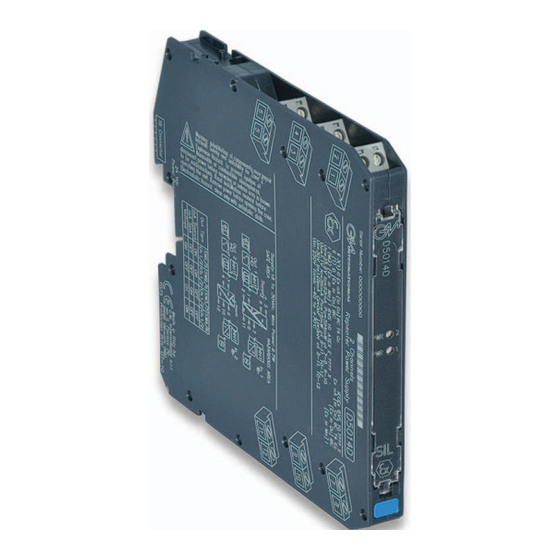
SIL 3 Repeater Power Supply
Hart, DIN-Rail and Termination Board,
Models D5014S, D5014D
D5014 - SIL 3 Repeater Power Supply
G.M. International ISM0103-3
Table of
Contents
Previous
Page
Next
Page
1
2
3
4
5
Advertisement
Table of Contents
Need help?
Do you have a question about the D5014S and is the answer not in the manual?
Ask a question
Questions and answers
Related Manuals for GM International D5014S
Repeater GM International D5014D Instruction Manual
Sil 3 repeater power supply hart, din-rail and termination board (11 pages)
Repeater GM International D1130S Instruction & Safety Manual
Sil 2 switch/proximity detector repeater relay output (12 pages)
Repeater GM International D1130D Instruction & Safety Manual
Sil 2 switch/proximity detector repeater relay output (12 pages)
This manual is also suitable for:
D5014d
Table of Contents
Print
Rename the bookmark
Delete bookmark?
Delete from my manuals?
Login
Sign In
OR
Sign in with Facebook
Sign in with Google
Upload manual
Upload from disk
Upload from URL


Need help?
Do you have a question about the D5014S and is the answer not in the manual?
Questions and answers