Table of Contents
Advertisement
Introduction
Thank you for purchasing our OOSSXX Video Security System. If you have any questions regarding the
installation or operation of your system, please email us at: info@oossxx.com . We will reply you as
soon as possible.
Disclaimer
We have used care to ensure the integrity and accuracy of the contents of this manual, however,
specifications or product features and operation may change from time to time.
This user manual will be updated when the product's function enhanced, and will regularly improve and
updated the product's description or the process. The updated details will be added into the new version.
Forgive us to not notice you in other ways.
The User is solely responsible for installing their system as per the local building and electrical Codes.
The parts, components and accessories mentioned in this manual are for illustrative purposes only and
may not represent the configuration of the purchased model. Please refer to the packing list for more
details.
Special statement
When using the video surveillance equipment, please strictly observe the applicable legal and
regulatory requirements regarding the installation, use and maintenance of the monitoring system.
OOSSXX is not responsible for the use of illegal video surveillance activities, or violation of Municipal use
codes.
About default settings:
l
Device factory default super administrator account:admin.
The Admin's default factory password is empty(no need input).
l
【IP address】: Set the IP address. Default: 192.168.1.18;
【Subnet Mask】:Set the subnet mask code default 255.255.255.0;
【default gateway】:Set the default gateway default 192.168.1.1
1
www.oossxx.com
Advertisement
Table of Contents

Summary of Contents for OOSSXX 6-in-1 DVR & DVR Security System
- Page 1 Introduction Thank you for purchasing our OOSSXX Video Security System. If you have any questions regarding the installation or operation of your system, please email us at: info@oossxx.com . We will reply you as soon as possible. Disclaimer We have used care to ensure the integrity and accuracy of the contents of this manual, however, specifications or product features and operation may change from time to time.
-
Page 2: Product Features Overview
1. Product features overview Product introduction This video Security system is one of OOSSXX advanced “Plug and Play” (PnP) security system products. It supports network video access, providing up to 5.0 Megapixel /4.0 Megapixel /3.0 Megapixel /2.0 Megapixel (1080P) real-time video preview, video encoding, archival storage and playback operation. - Page 3 Working humidity 10%--90%RH Dimension(mm) 255mm×220mm×40mm Power consumption ≤5W Power DC 12V 2A Camera Specification Model 1.0MP 1.3MP 2.0MP 4.0MP 5.0MP Sensor Sensor 1/3 Sensor Signal System PAL/NTSC 1280 x 1280 x 1920 x 1080 2688x1520 2592x1944 Resolution 16:9 16:9...
- Page 4 1.3 Functional feature • H.264,4ch/8ch/16ch real-time D1 1080P 3.0MP 4.0MP 5.0MP system • Built-in high-performance and high-stability module,100Mbps; • Camera automatically access DVR by cable; • Video preview / recording / playback / backup; • User-friendly (install simple matching, setup wizard, commonly used function menu, CMS);...
-
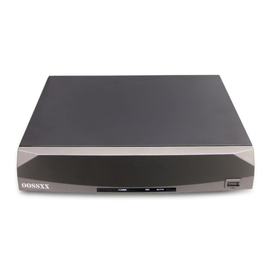
Page 5: Operation Explanation
2. Operation explanation Front panel indicators 2.2 Rear Panel Interface Connections 1:Video Input 2:VGA Output 3:Audio Output 4:HD-Output 5:Audio Input 6:NET Port 7:USB Port 8:RS485 Output 9:Power Input... - Page 6 1:Video Input 2: Video/Audio Output 3:HD-Output 4:Audio Input 5:NET Port 6:USB Port 7:RS485 Output 8:Power Input 9:VGA Output 1:Video Input 2: Video/Audio Output 3:VGA Output 4:HD-Output 5:Audio Input 6:NET Port 7:USB Port 8:RS485 Output 9:Power Input...
-
Page 7: Installation And Connection
3. Installation and connection 3.1 Installation Notice Note the following tips when installing the DVR system: 1, In order to ensure long term reliable operation, the DVR unit should be located away from moisture, elevated temperature, dusty environments, and installed in a well-ventilated location. - Page 8 This is to ensure all components are working. If any components are not functioning, please contact OOSSXX Customer Support. Setting up the cable connections The following instructions will show you how to set up the cables for the DVR, cameras, as well as a monitor or TV screen.
- Page 9 1. Connect a monitor or TV screen to your DVR. The DVR is compatible with any monitor or screen that uses a VGA or HD OUT connection. For purposes of this guide, we will use a VGA connection. Take a VGA cable, and connect one end to the VGA port on your monitor/screen and the other end to the VGA port on the back panel of your DVR.
- Page 10 4. Connect the camera video extension cable to the camera’s video cable and connect the camera power extension cable to the camera’s power cable. There should be a tag on the video cable to help you make sure the right end of the cable is at hand.
-
Page 11: Usb Connection
7. Make sure that the power switch is in the ON position. 3.4 USB Connection There are 2 USB port at back panel and 1 USB port at front panel, the 3 USB ports could be used for mouse, Flash stick, 3G &... - Page 12 Specific starting up steps are as follows: Plug in the power, the front panel power indicator is white. The device begins to start, as show in the following figure: If no video image is displayed, this may mean your TV (Monitor) cannot support Full HD picture, please change to another TV, or connect DVR system to TV (Monitor) by a VGA cable.
-
Page 13: Encode Setting
Password protection: If the password is continuous wrong seven times, the alarm will start. (Through reboot or after half an hour, the account will be unlocked automatically). For your system security, please modify your password in “User management” after first login. -
Page 14: Recording Setting
Step 3: Select channel 2, set the resolution as CIF, Frame Rate (fps) as 25, Bit Rate(Kb/s) as 512. Locally select [Advanced], click [Copy] button; Step 4: Select channel 3, locally choose [Advanced], and select [Paste]. Channel 4 is the same;... - Page 15 Method two to select channel: put the mouse arrow point at the channel number, and roll the roller to choose the channel number. 7.2 Redundancy Select redundancy function can realize recording file double backup, it says that you can back up the recording to two hard disks simultaneously.
-
Page 16: Recording Function
7.5 Recording Function Recording mode is divided into: manual, stop, schedule. Round box 【Manual】 displayed in “black”, is selected , otherwise it is not selected. Regardless of the channel in any state, after selected "Manual" button, the corresponding channel record by manual and produce H format file;... -
Page 17: Recording Playback
When users select the video format, according to their needs to set each channel, it is recommended to use the default (default time period is 24 consecutive hours, schedule, regular, detect, alarm simultaneously selected) 8. Recording playback Recording playback includes recording query, recording playback operation. How to open the recording playback: First method: in the preview screen please click the right mouse button, then it will pop-up the menu, select recording playback;... -
Page 18: Recording Play
8.1 Recording query , Select the time period and click query in the lower right corner of the interface finished query,click turn to the query interface In this interface, user can choose query again. 【 time period query 】... - Page 19 Key function play reverse playback stop playback slow play reverse fast fast play last profile next profile last frame next frame loop control full scream Any operation above can be available when you play. But please pay attention that you cannot operate last frame and next frame, these two option in the yellow box.
-
Page 20: Network Setting
9. Network setting Doing network setup through [Main Menu]>[System]>[Network] 【IP address】: Set the IP address. Default: 192.168.1.18; 【Subnet Mask】:Set the subnet mask code default 255.255.255.0; 【default gateway】:Set the default gateway default 192.168.1.1。 Make the equipment’s IP address and the router in the same network segment. For example, the router IP address is 192.168.1.1, and the subnet mask is 255.255.255.0. -
Page 21: Alarm Setting
11.1 Alarm setting 11.1.1 Channel First, you can choose the channel which you want to setting in the behind of [Channel] the drop-down box. [Enable] "Check" the box, then the switch is open, otherwise it is closed. Note: [Enabled] determines if the motion detect setting is in force, confirm the enable switch is open after setting. - Page 22 Click the left mouse button [region], [setup], pop-up interface, the user can press and hold the left mouse button to choose motion detection area, also can click the left mouse button to choose in the box was not continuous regional choice, the "red" display area to carry out motion detection regional, "black area"...
-
Page 23: Linkage Setup
11.1.5 Time interval In the interval of time setup (default 1 second), for example, multiple motion detect only trigger an alarm signal. 11.2 Linkage setup Linkage setup is to deal with motion setup after alarm. 11.2.1 Alarm output When motion detect occurs, set up corresponding linkage alarm output port of the external equipment... - Page 24 Recording delay: recording delay, when generate an alarm, the length of this linkage recording default 10s. Range 10-300. As below picture, setup the recording delay 300s: explanation: moving object after 300s trigger alarm After the complete the recording channel setup, it is still depending on the "recording setup in the settings".
- Page 25 If you want to record motion detect image, where you need to set the time period corresponding to the channel, so that the period" in the "recording setting period", generally select "00:00 - 24:00" button and here [Detect] the box below to select, after saving set. For more information, see chapter video settings 11.2.3...
- Page 26 Note: link PTZ, need set the parameter for the setting point, point-to-point tour, tour and etc. 11.2.5 Send EMAIL The box in the back show in black, it is selected, means that it will send email to note user when alarm occurred.
- Page 27 Email Set( 3) Configuration: The IP and DNS should be right, or the email can not send out.
- Page 28 Parameters Table smtp Port username Gmail smtp.gmail.co username Email pw Smtp.163.com username Authorization Manually opened smtp Smtp.126.com username Email pw smtp.qq.com username Authorization Manually opened smtp yahoo smtp.mail.yah username Email pw Manually opened smtp sohu smtp.sohu.co username Email pw sina smtp.sina.com...
-
Page 29: Show Message
For example: When detect the motion alarm, the email will be sent. 11.2.6 Show Message Alarm State” will be shown on screen while alarm happening, and it will disappear after clicking “Sure”. (The box next to “Show Message” is black after successfully enabled, otherwise, it has not been enabled.) 11.2.7 Buzzer... - Page 30 OOSSXX DVR Add IP Camera Setup Detail The first step: click the right mouse button menu, enter the main menu. Step two: enter the main menu, system settings, click the channel mode...
- Page 31 The third step: find the corresponding network mode and determine, and then restart, wait for the boot...
- Page 32 Step four: Right-click menu "remote device" manually add or a key to add, for all channels automatically add IPC within the LAN.
-
Page 33: Part 2 Remote Control
If you have any questions, please feel free to email us ,and we will respond as expeditious as possible. Part 2 Remote Control 1. WEB Remote View After connecting network, open IE browser, input device IP address to enter into the device. For details please refer to the web client user manual. - Page 34 Web main interface 2. CMS3.0 CMS software is used in a computer, and manipulates several devices at the same time. Log in Interface Main Interface...
- Page 35 Cloud Service User Manual 1. Log in Input this address into browser: http://www.topslink.net Note: need to install Active-X when first use. There are two methods to install it. 1. Install automatically Use IE browser to log in Cloud service client, it will prompt you install Active-X, as follow 2.
-
Page 36: Access Device
After successful installation, it will appear a fold named TSCloudClient under the directory C:\Program Files. 2. access device 2.1 log in system 2.1.1 Choose language There are five kinds of language to choose, which are Chinese, English, Spanish, Portuguese, Russian. - Page 37 Click “register”, enter into the registering page to enroll. Log in system Use registered account to log in; it will appear the interface shown as below Preview: view device remotely Manager: add and manage device User info: modify user password Log out: log out system 2.2 device management...
-
Page 38: Edit/Delete Device
2.2.1 Add device Click “add”, Input the info such as device ID, device name, log in name, log in password etc. 2.2.2 edit/delete device Choose the added device, click to edit the info, click to delete the device. 2.3 view device remotely... - Page 39 Choose the device you want on the left, and then double click. It will show as below. In this page, you can view by sub stream, playback and configuration remotely. 2.4 user info Click “user info”, enter into the page below.
- Page 40 2.5 log out system Click “log out”, then log out the system. XVR APP Installation Steps: 1. First, m ake s ure t he D VR i s c onnected t o y our ...
- Page 41 9. Create a n ame f or t he d evice ( no s pace o r s pecial c haracters f or t he ...
- Page 42 If the equipment and mobile phone in the same local LAN, can added automatically search equipment, and then add GID (imei number): by adding the equipment, the equipment identification number to connect to OOSSXX server, so you can avoid complex network Settings, such as port mapping and the IP address. project...
- Page 43 4 Icon button function description Button icon The keyboard Play the video Add a new device Screenshots Start/stop video Audio intercom The equipment list Screenshots and video files The remote video file search and playback Local Settings Help...
- Page 44 5: The remote video playback Click main menu remote playback, into remote video search page Click on the upper right corner of the video button to playback.
Need help?
Do you have a question about the 6-in-1 DVR & DVR Security System and is the answer not in the manual?
Questions and answers
Can you give me instructions on how to install both IP and wired cameras?
To install IP and wired cameras for the OOSSXX 6-in-1 DVR & DVR Security System:
1. Install Wired Cameras:
- Connect the DVR to a monitor using the supplied HD OUT cable.
- Place all wired cameras near the DVR and connect each camera to the DVR using the appropriate cables.
- Power on the DVR and the cameras.
- Confirm video is displayed from all cameras on the monitor before mounting them in their final locations.
2. Install IP Cameras:
- Right-click to access the main menu on the DVR.
- Go to System Settings > Channel Mode and select the appropriate network mode.
- Restart the DVR.
- After reboot, right-click and select "Remote Device."
- Use "Manually Add" or "One Key Add" to automatically add all IP cameras within the local network (LAN).
Ensure the DVR is grounded properly and set up in a well-ventilated, dry location.
This answer is automatically generated
My DVR is offline, how do you put it back online?
To bring the OOSSXX 6-in-1 DVR & DVR Security System back online, follow these steps:
1. Ensure the DVR is properly connected to your router using an Ethernet cable.
2. Turn on the DVR by plugging in the power; the front panel power indicator should be white.
3. If no video appears on the monitor, try using a different monitor or connect using a VGA cable (lower resolution).
4. Right-click on the monitor screen, go to "System Settings" > "Network" > click "Net Service."
5. Check the Cloud ID at the bottom of the screen.
6. On your phone, install the XVR app from the app store.
7. Register a new account, create a username and password, and log in.
8. In the app, go to "Devices" > tap "+" > create a device name (no spaces or special characters).
9. Scan the QR code on the DVR’s network screen or manually enter the Cloud ID.
10. Enter the DVR’s username and password (default: admin with no password), then click "SAVE."
11. Select the device and click "Start Preview" to view your cameras.
This brings the DVR system back online and viewable from your phone.
This answer is automatically generated
how do youreset the adim pass word
The OOSSXX 6-in-1 DVR & DVR Security System has a factory default super administrator account with the username "admin" and a default password that is empty (no need to input a password). If you need to reset the admin password, the provided context does not contain specific instructions for resetting it.
If you have forgotten the password, try using the default credentials. If that does not work, you may need to check the DVR's manual or contact the manufacturer for further assistance.
This answer is automatically generated