Table of Contents
Advertisement
Advertisement
Table of Contents

Subscribe to Our Youtube Channel
Related Manuals for Dahua ARC5402A-GW

Summary of Contents for Dahua ARC5402A-GW
- Page 1 Video Alarm Control Panel User’s Manual V1.0.1...
-
Page 2: Legal Statement
Legal Statement Trademark VGA is the trademark of IBM. Windows logo and Windows are trademarks or registered trademarks of Microsoft. Other trademarks and company names mentioned are the properties of their respective owners. Disclaimer Within the scope allowed by applicable laws, in any case, this company won’t compensate ... -
Page 3: Cybersecurity Recommendations
Cybersecurity Recommendations Mandatory actions to be taken towards cybersecurity 1. Change Passwords and Use Strong Passwords: The number one reason systems get “hacked” is due to having weak or default passwords. It is recommended to change default passwords immediately and choose a strong password whenever possible. - Page 4 ● Only forward the HTTP and TCP ports that you need to use. Do not forward a huge range of numbers to the device. Do not DMZ the device's IP address. ● You do not need to forward any ports for individual cameras if they are all connected to a recorder on site;...
- Page 5 Ideally, you want to prevent any unauthorized physical access to your system. The best way to achieve this is to install the recorder in a lockbox, locking server rack, or in a room that is behind a lock and key. 15.
-
Page 6: Preface
Preface Overview This document elaborates device structure, installation and system functional operation of video alarm control panel. Symbol Definition The following symbols may appear in this document. And their meanings are as follows: Symbol Note It indicates a potentially hazardous situation which, if not avoided, could result in death or serious injury. -
Page 7: Important Safeguards And Warnings
Important Safeguards and Warnings The following description is the correct application method of the device. Please read the manual carefully before use, in order to prevent danger and property loss. Strictly conform to the manual during application and keep it properly after reading. Operating Requirement ... -
Page 8: Table Of Contents
Table of Contents Legal Statement ..............................I Cybersecurity Recommendations ........................II Preface ..................................V Important Safeguards and Warnings ......................VI 1 Overview ................................1 1.1 Product Introduction ..........................1 1.2 Product Function ............................1 1.3 Typical Network ............................1 2 Device Structure ..............................3 2.1 Structure Dimension .......................... - Page 9 4.8 Mode Setting ............................27 4.9 PGM Setting ............................28 4.10 Event Reporting Setting ........................29 4.11 Time Setting ............................29 4.11.1 Time Setting ..........................29 4.11.2 DST Setting ..........................30 4.11.3 Time Format ..........................31 4.12 Call Center Setting ..........................31 4.13 Delay and Volume Setting ........................
-
Page 10: Overview
Overview Product Introduction Video alarm control panel integrates alarm information acquisition, alarm output and linkage control, telephone alarm, audio-video acquisition encoding, recording playback, voice message and video output. With strong stability and reliability, it applies to communities, villas and shops. Product Function Its main functions are as follows: Support 100M network. - Page 11 Figure 1-1...
-
Page 12: Device Structure
Device Structure Structure Dimension External dimension of the device is shown in Figure 2-1 and Figure 2-2. The unit is mm. Figure 2-1... -
Page 13: Front Panel
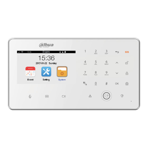
Figure 2-2 Front Panel Front panel is shown in Figure 2-3. For keys and icons, please refer to Table 2-1. Figure 2-3 Key or Icon Description Enter number 0~9, page up/down. Enter English letters A~Z and a~z. In homepage, press [1] to customize arm quickly; press [2] to view failure alarm info;... -
Page 14: Rear Panel
Key or Icon Description Red light on during arm. Away arm and disarm by swiping a registered card. Red light on when there is an alarm. Table 2-1 Rear Panel Rear panel includes battery box and all kinds of ports, as shown in Figure 2-4. Please refer to Table 2-2 for details. - Page 15 Port/slot Description RING-I/TIP-I: telephone port. 485-A/485-B: 485 device port. LAN: network port. SIM Card Slot Support SIM cards of local operators. Initialization Hole Insert both ends of the cable into two holes for about 5s, so as to restore factory settings. Table 2-2 Figure 2-5...
-
Page 16: Installation
Installation SD Card Installation This device is able to install maximum 128G SD card, in order to save alarm recordings. Step 1 Open battery cover and take out the battery. Step 2 Push SD card into the slot in accordance with arrow direction in Figure 3-1. SD card can only be installed and dismantled when the power is off. -
Page 17: Battery Installation
Figure 3-2 Battery Installation This device installs 1900mAh lithium battery, provides emergency power when 12V power supply fails and thus ensures its normal operation. The device will be rebooted 3 minutes after 12V power supply is connected again, so as to ensure normal use of all functions. Power supply of lithium battery is as follows: Some modules with relatively high power consumption cannot work normally, including ... -
Page 18: Cable Installation
Figure 3-3 Cable Installation This device provides cable port to connect 12V power, wired detector, wired siren, wired telephone and alarm output device. Step 1 Insert cable into corresponding pin header socket. Step 2 Neaten all cables and lead them out of the wiring duct. Figure 3-4 Panel Installation This device adopts wall installation. -
Page 19: Non-86 Box Installation
Figure 3-5 3.5.2 Non-86 Box Installation Step 1 Open holes on wall in accordance with position of screw B of bracket, and embed expansion bolts. Step 2 Fix installation bracket directly on wall with screw B. Step 3 Hang the device on the hook of installation bracket in accordance with arrow direction in Figure 3-6. -
Page 20: Operation Instruction
Operation Instruction Password Setting 4.1.1 First Login For security reason, please set password at first time login, as shown in Figure 4-1. Figure 4-1 ] to select text box, and press numeric key to input “Password” and Step 1 Press [ ] or [ “Confirm”. -
Page 21: Homepage Introduction
Figure 4-2 ], select the text box, and press numeric keys to enter “Old Step 3 Press [ ] or [ Password”, “New Password” and “Confirm”. New password shall not be the same as old password. ], select “Save” and press [OK] to save the settings. Step 4 Press [ ] or [ Homepage Introduction... - Page 22 Symbol Description Mobile signal strength symbol of SIM card, representing that SIM card has been installed. WIFI network symbol, representing that WIFI connection is enabled. The system is in disarm status. It displays in arm status. USB symbol, representing a USB has been inserted. System is disarmed.
-
Page 23: Network Setting
Symbol Description WIFI, 2G and P2P. Others: Set time delay, exit/ screen lock time, volume and key tone. Initialization: reboot the device or restore factory setting. Alarm center: Set alarm center info, supporting 2 groups of alarm center. Table 4-1 Network Setting 4.3.1 Wired Network... -
Page 24: Wifi
4.3.2 WIFI The device supports WIFI network connection. ], select “System” and press [OK]. Step 1 In the homepage, press [ ] or [ ], select “Network” and press [OK]. Step 2 Press [ ] or [ ], select “WIFI” and press [OK]. Step 3 Press [ ] or [ The interface is shown in Figure 4-5. - Page 25 search and connect again. Pairing function is used when the device connects WIFI network, with which mobile phone APP is connected. When mobile phone APP inputs WIFI password to connect, the device chooses “Pairing” to connect this WIFI network. For details, please refer to user’s manual of mobile phone APP.
-
Page 26: P2P
Figure 4-8 Step 4 Press [ ] or [ ], select and press [OK]. Switch to and enable 2G function. ], select “SMS Title” text box and press [OK]. Step 5 Press [ ] or [ Please refer to “Appendix 1 Operating Instructions of Input Method”, input SMS title info, which is used to differentiate from SMS contents. -
Page 27: Wireless Enrollment
save setting and then you can arm/disarm on APP to manage more than one device. ], select “System” and press [OK]. Step 1 In the homepage, press [ ] or [ ], select “Network” and press [OK]. Step 2 Press [ ] or [ ], select “P2P”... -
Page 28: Add Wireless Device
4.4.1 Add Wireless Device ], select “Setting”, then select “Enroll” and press Step 1 In the homepage, press [ ] or [ [OK]. The interface is shown in Figure 4-12. Figure 4-12 Step 2 Press [ ] or [ ], select and press [OK]. -
Page 29: Delete Wireless Device
Repeat above steps, until it is paired successfully. Alternatively, slide the tamperproof switch of the case manually to make red light flash fast until it is paired successfully. ● Zone no. of wireless detector starts from 3 in sequence. ● Zone no. of wireless siren starts from 44 in sequence. ●... -
Page 30: Camera Management
Figure 4-15 Step 3 Press [ ] or [ ], select in the corresponding wireless device column, and press [OK]. “Confirm” prompt box will pop up. ], select “Yes” and press [OK] to delete it. Step 4 Press [ ] or [ Camera Management Add and delete remote IP camera. - Page 31 Figure 4-16 Search Press [ ] or [ ], select and press [OK]. Search the info about all cameras in the same network segment, as shown in Figure 4-17. Press corresponding numeric key to page up and down. Figure 4-17 Press [ ] or [ ], select a camera and press [OK].
-
Page 32: Modify/View Camera Parameters
Figure 4-19 Press [ ] or [ ], select corresponding parameter text box, input numbers, or input them by reference to “Appendix 1 Operating Instructions of Input Method”. For specific parameter descriptions, please refer to Table 4-2. Parameter Description Channel The system identifies idle channel number automatically, which cannot be modified. -
Page 33: Delete Camera
4.5.3 Delete Camera ], select “Setting” and press [OK]. Step 1 In the homepage, press [ ] or [ ], select “Camera” and press [OK]. Step 2 Press [ ] or [ Step 3 Press [ ] or [ ], select and press [OK]. -
Page 34: Delete Rfid Card
Figure 4-21 Step 4 Swipe FRID card in the card-swiping zone. Display ID, representing successful identification. Then, press [ ] or [ ], select “Name” text box and press [OK] to enter card name. ], select “Save” and press [OK] to save the settings. Step 5 Press [ ] or [ 4.6.2 Delete RFID Card... - Page 35 Figure 4-22 Step 3 Press [ ] or [ ], select a zone to be set and press [OK]. The interface is shown in Figure 4-23. Figure 4-23 Step 4 Press [ ] or [ ], select parameters and press [OK] to select or modify. For specific parameter descriptions, please refer to Table 4-3.
-
Page 36: Mode Setting
Parameter Description PSTN Two check boxes represent PSTN 1 and PSTN 2 respectively. After selection, alarm info will be reported to the selected PSTN when an alarm is triggered in the zone. Record Four check boxes represent record channel 1~ 4. Channel After selection, the selected channel will start recording when an alarm is triggered in the zone. -
Page 37: Pgm Setting
Figure 4-25 Step 4 Press [ ] or [ ], press [OK] and select the zones. Repeat the operation to select multiple zones. One zone can be added to different modes. ], select “Save” and press [OK] to save the settings. Step 5 Press [ ] or [ PGM Setting... -
Page 38: Event Reporting Setting
4.10 Event Reporting Setting Set reporting position of alarm info in case of SOS, power off and tamper. ], select “Setting” and press [OK]. Step 1 In the homepage, press [ ] or [ ], select “Other” and press [OK]. Step 2 Press [ ] or [ The interface is shown in Figure 4-27. -
Page 39: Dst Setting
Figure 4-28 Step 4 Press [ ] or [ ], select Year/Month/Day/Hour/Minute/Second text box, and press numeric keys to input numbers. ], select “Save” and press [OK] to save the settings. Step 5 Press [ ] or [ 4.11.2 DST Setting ], select “System”... -
Page 40: Time Format
time period. ], select “Save” and press [OK] to save the settings. Step 6 Press [ ] or [ 4.11.3 Time Format ], select “System” and press [OK]. Step 1 In the homepage, press [ ] or [ ], select “Time” and press [OK]. Step 2 Press [ ] or [ ], select “Time Format”... -
Page 41: Delay And Volume Setting
Figure 4-31 ], select “Call Group” text box and press [OK]. Step 3 Press [ ] or [ Switch between Call Center 1 and Call Center 2. Taking “1” for example, it means to view or set Call Center 1. Step 4 Press [ ] or [ ], select other parameter text boxes, input with input method or... -
Page 42: Sd Card Format
Figure 4-32 Step 3 Press [ ] or [ ], select corresponding parameter text boxes, and press numeric keys to input time value. For introduction to every parameter, please refer to Table 4-5. Key tone is selected by pressing [OK]. Parameter Description If away arm is chosen and “Enter Delay”... -
Page 43: Initialization
again. 4.15 Initialization Reboot the device or restore factory defaults. 4.15.1 Reboot ], select “System” and press [OK]. Step 1 In the homepage, press [ ] or [ ], select “Initialization” and press [OK]. Step 2 Press [ ] or [ ], select “Reboot”... -
Page 44: View Version Info
Figure 4-34 The last 45 log info is displayed. Press numeric keys to page up and down. is used to delete all logs. Step 4 Press [ ] or [ ], and select The interface is shown in Figure 4-35. Press [ ] or [ ], select text box and press ], select “Search”... -
Page 45: Event
Figure 4-36. Figure 4-36 4.17 Event Search and view events; backup linkage videos of the events. 4.17.1 Search and View Events ], select “Event” and press [OK]. Step 1 In the homepage, press [ ] or [ The interface is shown in Figure 4-37. Figure 4-37 Display the last 45 events;... -
Page 46: Play Record
], select “Search” to display the numeric keys to input numbers. Then, press [ ] or [ last 45 events within the stipulated time period. Figure 4-38 Step 3 Press [ ] or [ ], select an event and press [OK] to view detailed info. 4.17.2 Play Record If SD card has been installed and alarm linkage record has been set, after an alarm event, the record can be played at detailed info interface. -
Page 47: Arm And Disarm
With search function, search event info that needs to backup videos. Insert USB disk. Step 1 At event interface, press [ ] or [ ], select and press [OK] Step 2 Press [ ] or [ ], select an event and press [OK] to select it. Repeat the operation and select multiple events. - Page 48 4.18.1.2 Away Arm Step 1 Press [ ] and password input box will pop up. Step 2 Press numeric keys to input password. Step 3 Press [OK]. The system beeps all along, and enters exit delay countdown. Status bar at the top of LCD screen displays “Arm”, so zone of “Away Arm” mode enters armed status.
-
Page 49: Arm And Disarm With Card
4.18.1.4 Disarm Step 1 Press [ ] and password input box will pop up. Step 2 Press numeric keys to input password. Step 3 Press [OK]. The system beeps twice, and status bar at the top of LCD screen displays “Disarm”... -
Page 50: Arm And Disarm With Remote Control
Figure 4-44 4.18.2.2 Disarm In armed status, swipe a card at card-swiping area. The system beeps twice, and LCD shows “Disarm” at the top. Remove the last arm, and all zones enter disarmed status. 4.18.3 Arm and Disarm with Remote Control The system supports to arm and disarm with remote control, so you can perform stay arm, away arm, disarm and SOS remotely. -
Page 51: Arm And Disarm With Mobile Phone App
4.18.4 Arm and Disarm with Mobile Phone APP The system supports to arm and disarm with mobile phone APP. For specific operation, please refer to user’s manual of mobile phone APP. 4.19 Duress Password The device supports duress password. When you enter duress password, the system will produce duress event alarm, and report alarm info with default linkage SMS and PSTN, which won’t produce a log. -
Page 52: Sound Recording And Playback
4.21 Sound Recording and Playback 4.21.1 Sound Recording Press [ ] to record sound, at most 30s each time. Save it in system. 4.21.2 Playback Press [ ] to play the last recording. 4.22 Video Preview Press [ ] to preview video in the recording channel, press [ ] or [ ] to switch channels, and press [... -
Page 53: Appendix 1 Operating Instructions Of Input Method
Appendix 1 Operating Instructions of Input Method During setting of some parameters, switch among English capital letter and small letter, number and symbol. For example, modify zone name to be door12 in the following steps. Step 1 At zone configuration interface, press [ ] or [ ], select name text box and press [OK].
Need help?
Do you have a question about the ARC5402A-GW and is the answer not in the manual?
Questions and answers
hello i want to connect my device with a number phone PTSN and use ring1 and tip you can see it in the picture so the call is ready have it but the problem is the call is aleatoire she keep calling without an intrusion or arming the device i dont know from where tha problem and finaly thanks dear stuff