Advertisement
Advertisement
Table of Contents

Related Manuals for Motorvac TRANSTECH IV

Summary of Contents for Motorvac TRANSTECH IV
- Page 1 TRANSTECH IV Transmission Service System 500-1125 Service Manual...
-
Page 2: Table Of Contents
3. FEATURES AND FUNCTIONS .............6 4. MACHINE OVERVIEW .................8 5. MACHINE SETUP.................10 6. BASIC OPERATION ................12 7. THEORY OF OPERATION ..............19 8. TROUBLESHOOTING .................22 9. FLUID FLOW DIAGRAMS..............27 10. WIRING DIAGRAM................31 11. SPARE PARTS LIST ................32 ZIM12-00505 Rev. 1 TransTech IV Service Manual... -
Page 3: Safety Information
Use only approved automatic transmission fluid. Do not swallow or ingest any chemicals. Use with adequate ventilation. Avoid breathing vapors. Do not store chemicals in or on the machine (other than automatic transmission fluid). ZIM12-00505 Rev. 1 TransTech IV Service Manual... - Page 4 Keep battery acid away from skin or eyes. In case of eye contact, flush with clean water for 15 minutes and get medical attention. ZIM12-00505 Rev. 1 TransTech IV Service Manual...
-
Page 5: Specifications
Shipping Height: 41“(104 cm) Shipping Width: 24” (61 cm) Shipping Depth: 19” (48 cm) Shipping Weight: 90lbs (40.8 kg) Clean pump flow 20° C 1 GPM Dipstick drain 20° C, 5/16 tube 1 Quart/min ZIM12-00505 Rev. 1 TransTech IV Service Manual... -
Page 6: Features And Functions
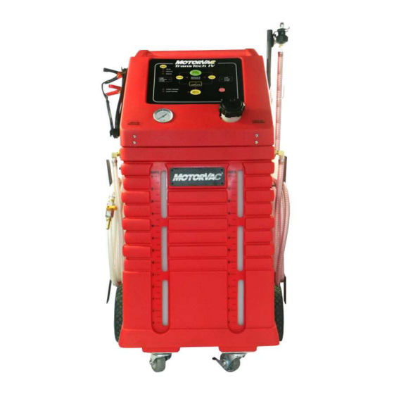
FEATURES AND FUNCTIONS The front of the TRANSTECH IV cabinet contains the control panel, the fluid fill neck for adding new transmission fluid, and the fluid level windows. Front View - Control Panel Features and Functions MODE Button - Toggles from Inline to Dipstick and enters manual mode for both... - Page 7 STOP Button – Pauses service and stops alarms. Hold for 5 seconds to reset unit. EMPTY WASTE Button - Empties fluid from unit’s waste tank. MODE Button – Toggles between four different modes (Inline/Dipstick etc) ZIM12-00505 Rev. 1 TransTech IV Service Manual...
-
Page 8: Machine Overview
Clean Fluid Hose – Clean ATF is introduced to the vehicle through this hose for both In-Line and Dipstick modes. Dipstick Return Hose – Draws dirty ATF from the vehicles in Dipstick Mode. ZIM12-00505 Rev. 1 TransTech IV Service Manual... - Page 9 Disposal Hose Ball Valve - Open manually before EMPTY WASTE button is pushed. Waste Disposal Hose - Is inserted into the shop’s fluid recycling container or into a suitable container for proper disposal of used transmission fluid. ZIM12-00505 Rev. 1 TransTech IV Service Manual...
-
Page 10: Machine Setup
Both tanks should have fluid approximately at the zero mark on the front of the cabinet. 7. Return the hoses to their original location. 8. The initial setup is complete. ZIM12-00505 Rev. 1 TransTech IV Service Manual... - Page 11 2. Start the vehicle. 3. Determine ATF flow direction then fully open H-adapter valve. 4. With the male to male couplers connected to the TransTech IV hoses, attach the INLINE RETURN hose to the transmission output side of the H-adapter. Attach CLEAN FLUID hose to the transmission return side of the H-adapter valve.
-
Page 12: Basic Operation
Control Panel Pressure Gauge Automatic Fluid Exchange Operation. 1. Make sure the TransTech IV new fluid tank is filled with the correct type and amount of Transmission Fluid. 2. Connect TransTech IV power leads to the vehicle’s battery. 3. With vehicle running, pressure should be present at the TransTech IV pressure gauge and the START ENGINE light should be on solid. - Page 13 Failure to do so will result in waste tank overflowing! 1. Make sure the TransTech IV new fluid tank is filled with the correct type and amount of transmission fluid.
- Page 14 ONLY when the service is paused. Any ATF added while the unit is performing a service will not be properly measured and may result in an OVER FILL of the vehicle’s transmission! ZIM12-00505 Rev. 1 TransTech IV Service Manual...
- Page 15 Failure to do so will result in waste tank overflowing! 1. Fill the TransTech IV new fluid tank with the correct type and amount of Transmission Fluid.
- Page 16 12. The COMPLETE light will turn on when the service is complete and alarm will sound. Press STOP button to silence alarm. 13. Remove the Dipstick fill adaptor and check the level of transmission fluid in the vehicle. ZIM12-00505 Rev. 1 TransTech IV Service Manual...
- Page 17 DRAIN or FILL buttons. 15. Direct waste hose to a suitable container; open the ball valve on the end of the waste hose and press EMPTY WASTE to empty dirty fluid tank. ZIM12-00505 Rev. 1 TransTech IV Service Manual...
- Page 18 EMPTY WASTE button is released. 6. Tip the unit slightly backwards to let the fluid flow toward the back of the tank for complete evacuation. Pressing the STOP button for five seconds will reset the unit. ZIM12-00505 Rev. 1 TransTech IV Service Manual...
-
Page 19: Theory Of Operation
- Press Drain button OUTPUT – Inline Solenoid turns on DURING PAN DRAIN INPUT – Pan drain complete when Inline Pressure Switch opens OUTPUT – Inline Solenoid turns off, alarm sounds, Stop Engine LED flashes ZIM12-00505 Rev. 1 TransTech IV Service Manual... - Page 20 EXCHANGE COMPLETE INPUT – When the Clean Tank Level Switch closes, the unit drains until the TransTech has drained the same amount of fluid as it filled. OUTPUT – Complete LED flashes alarm sounds. ZIM12-00505 Rev. 1 TransTech IV Service Manual...
- Page 21 OUTPUT – Unit alternates between filling and draining until the Clean Tank is empty (Level Switch closes). The unit then drains until it has drained the same amount of fluid as it filled. ZIM12-00505 Rev. 1 TransTech IV Service Manual...
-
Page 22: Troubleshooting
12 VDC with the TransTech on? Replace power harness Is the tank backlight on? Is 12 VDC being supplied at the power harness connection to the PCB? Replace power Replace PCB harness ZIM12-00505 Rev. 1 TransTech IV Service Manual... - Page 23 Empty Waste LED on solid? Add fluid to waste Replace Waste Is the pump on? Replace PCB tank Tank level switch Replace Test dipstick and Waste Pump empty waste solenoids both should be on. Replace as necessary ZIM12-00505 Rev. 1 TransTech IV Service Manual...
- Page 24 TransTech pressure gauge Check inline pressure switch for Check hoses for kinks, continuity. Is the switch closed? increase engine RPM, replace inline filter if necessary Check wiring Replace Inline Pressure Switch ZIM12-00505 Rev. 1 TransTech IV Service Manual...
- Page 25 Change pressure tube assembly. Empty clean Replace Clean tank before reconnecting pressure tube to board. Tank level switch EMPTY WASTE FEATURE DOES NOT AUTOMATICALLY STOP Replace Waste tank level switch ZIM12-00505 Rev. 1 TransTech IV Service Manual...
- Page 26 1) Ensure that the clean tank fluid level is around the zero mark at the front of the cabinet. 2) Hook TransTech IV to 12 VDC power source. 3) (see picture for this step) Set multimeter for voltage and put the probes on the top 2 pins.
-
Page 27: Fluid Flow Diagrams
FLOW DIAGRAMS TransTech IV Flow Diagram To Car Clean Fluid Pump (Off) External “Clean Hose” 10 ft. Check Filter From Filter Valve Waste Fluid (Off) To Waste Sol # 2 (Off) External “Dirty Receptacle Hose” 10 ft. Sol # 1... - Page 28 FLOW DIAGRAMS (CONT’D) TransTech IV Flow Diagram To Car Clean Fluid Pump (On) External “Clean Hose” 10 ft. Check Filter From Valve Waste Fluid (Off) Filter To Waste Sol # 2 (Off) External “Dirty Receptacle Hose” 10 ft. Sol # 1...
- Page 29 FLOW DIAGRAMS (CONT’D) TransTech IV Flow Diagram To Car Clean Fluid Pump (Off) External “Clean Hose” 10 ft. Check Filter From Valve Waste Fluid Filter (On) To Waste Sol # 2 (Off) External “Dirty Receptacle Hose” 10 ft. Sol # 1...
- Page 30 FLOW DIAGRAMS (CONT’D) TransTech IV Flow Diagram To Car Clean Fluid Pump (Off) External “Clean Hose” Check Filter 10 ft. Valve Waste Fluid From Pump (On) Filter To Waste Sol # 2 (Off) Receptacle External “Dirty Hose” 10 ft. Sol #...
-
Page 31: Wiring Diagram
YELLOW W/RED Waste Tank Level Switch YELLOW W/RED (050-2700) YELLOW Solenoid#1 (Dipstick Solenoid) YELLOW (200-1106) GRAY Solenoid#2 (Bypass Solenoid) GRAY (200-1107) BROWN Solenoid#3 (Waste Solenoid) BROWN (200-1108) External 12VDC Battery LED light (200-1604) ZIM12-00505 Rev. 1 TransTech IV Service Manual... -
Page 32: Spare Parts List
Assembly Solenoid#2 Inline Bypass 200-1106 Assembly Solenoid#1 High Flow 200-1108 Assembly Solenoid#3 Waste Pump Outlet 200-1109 Assembly Filter Dipstick Dirty Hose 200-1111 Assembly Pressure Switch TTIV 200-8650 TT IV Assy. Check Valve Clean Pump ZIM12-00505 Rev. 1 TransTech IV Service Manual... - Page 33 200-1604 Internal light LED type 010-0027 Wheel (8 x 1.75") 011-0003 Sorter rack for adaptor tray 040-0604 Cap nut (1/2" ID push on) 200-9001 Pressure Gauge Assembly 010-6101 Swivel caster with brake lock ZIM12-00505 Rev. 1 TransTech IV Service Manual...
- Page 34 Spare Parts Additional Service Parts for the TRANSTECH IV Transmission System. Part # Description 010-5004 Hose bracket 010-5602 Adapter tray 020-8043 Harness External Power 030-0055 Ball Valve 1/4FNPT Brass Chrome Plated 040-0507 Axle Bushing (Black Nylon) 040-2200 Threaded Standoff (for adapter box) 050-1000 Filter inline ½”MPT.
Need help?
Do you have a question about the TRANSTECH IV and is the answer not in the manual?
Questions and answers