
Related Manuals for SiboTech EP-321MP

Summary of Contents for SiboTech EP-321MP
-
Page 1: User Manual
PROFIBUS DP / Modbus TCP Gateway EP-321MP User Manual REV 1.2 Sibotech Automation Co., Ltd Technical Support: 021-5102 8348 E-mail:support@sibotech.net... -
Page 2: Table Of Contents
6.6.2 Upload Configuration........................27 6.6.3 Download Configuration........................27 6.7 Open and Save Configuration........................28 6.7.1 Save Configuration..........................28 6.7.2 Open Configuration........................... 29 6.8 Export EXCEL..............................29 6.9 Monitor I/O Data............................30 7. Application................................32 8. Step7 Read and Write Gateway Data........................33 9 Installation................................35 www.sibotech.net/en... - Page 3 9.1 Mechanical Dimension..........................35 9.2 Installation..............................35 Appendix: Using STEP7 Set PROFIBUS DP......................37 www.sibotech.net/en...
-
Page 4: Product Overview
1 Product Overview 1.1 General This document describes every parameters of the gateway EP-321MP and provides using methods and some announcements that help users use the gateway. Please read this document before using the gateway. For further information, documentation etc., please visit the SiboTech website: http://www.sibotech.net/En/... -
Page 5: About The Gateway
[10] Operating temperature: -4 ° F to 140 ° F (-20℃~60℃), relative humidity 5% ~ 95% (non-condensing); [11] External Dimensions (W*H*D): 1.57in*4.92in*4.33in (40mm* 125mm * 110mm); [12] Installation: 35mm DIN rails; [13] Protection class: IP20; [14] Test standard: Complies with EMC test standards. www.sibotech.net/en... -
Page 6: Attention
Please check the wiring, before any wrong or short circuit. 2.5 Related Products Related products include: PCA-100, ENC-310, ENC-311, ENB-302, PCO-150S and so on More information about these products, please visit: http://www.sibotech.net/En/, or dial technical support line: +86-21-5102 8348 www.sibotech.net/en... -
Page 7: Hardware Description
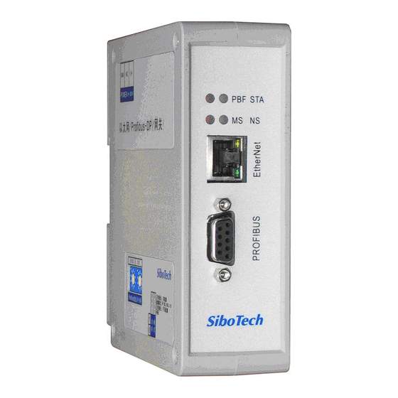
3 Hardware Description 3.1 Product Appearance Power supply Ethernet PROFIBUS DP DIP Switch Rotary address Switch www.sibotech.net/en... -
Page 8: Indicators
Configuration mode, IP address is 192.168.0.10 (fixed), this mode can Off or On read and write configuration data but cannot finish communication between Modbus TCP and PROFIBUS DP Notes: Restart EP-321MP (power off and power on) after resetting the configuration to make the configuration take effect! www.sibotech.net/en... -
Page 9: Profibus Dp Address Setting Switch
The 2-code rotary switch in the left-side is used for setting the PROFIBUS DP address of the device. In this example, the PROFIBUS node address will be 42 ((4x10) + (2x1)). 3.4 Connectors 3.4.1 PROFIBUS DP Connector PROFI-A PROFI-A PROFI-B DB9 pin Function PROFI_B, Data positive GND (optional) PROFI_A, Data negative www.sibotech.net/en... -
Page 10: Ethernet Connector
3.4.2 Ethernet Connector Signal Descriptions TXD+,Tranceive Data+,output TXD-,Tranceive Data-,output RXD+,Receive Data+,input Bi-directional Data+ Bi-directional Data- RXD-,Receive Data-,input Bi-directional Data+ Bi-directional Data- 3.4.3 Power Connector 24V+ Function GND, Power ground NC, not connected 24V+, 24VDC www.sibotech.net/en... -
Page 11: Modbus Tcp Master
The Ethernet port supports Modbus TCP master functions, as follows: Data exchange of Modbus TCP and PROFIBUS DP of EP-321MP is set up through “mapping”. There are two data buffer areas, one is PROFIBUS DP network input buffer and the other is PROFIBUS DP network output buffer. -
Page 12: Modbus Tcp Slave
… … … … Data exchange of Modbus TCP and PROFIBUS DP of EP-321MP is set up through “mapping”. There are two data buffer areas, one is PROFIBUS DP network input buffer and the other is PROFIBUS DP network output buffer. -
Page 13: Configuration Software Ep-123
Here is to introduce the use of EP-123.Double-click on the icon to enter the main interface: 6.2 User Interface EP-123 user interface include: title bar, menu bar, toolbar, status bar, equipment plate, configuration plate and comment plate. Note: In this software, all gray parts cannot be modified. www.sibotech.net/en... - Page 14 Conflict detection: To check whether there are some conflicts with configured commands in the gateway memory data buffer Auto mapping: Used to automatically calculate the mapped memory address without confliction by each command Export Excel: Export the configuration into Excel www.sibotech.net/en...
-
Page 15: Equipment View Operation
Monitor I/O data : Monitor the gateway memory buffer data 6.3 Equipment View Operation 6.3.1 Equipment View Interface 6.3.2 Equipment View Operation Mode For equipment interface, support three operation modes: edit menu, edit toolbar and right click edit menu. www.sibotech.net/en... -
Page 16: Equipment View Operation Types
3) Add commands: Left click on the node, and then perform the operation of adding command to add a command for the node. It will pop up the command selecting dialog box for users to choose. Shown as below: Select the command: Double click command item www.sibotech.net/en... -
Page 17: The Operation Of Configuration Interface
The configurable items include: Bus Type: PROFIBUS DP PROFIBUS DP input bytes: set by the PROFIBUS DP master configuration software PROFIBUS DP output byte: set by the PROFIBUS DP master configuration software Double fault clear: open and close optional. www.sibotech.net/en... -
Page 18: Ethernet Configuration Interface
Delay between polls: A Receive the right response after one Modbus command has been sent or sending next Modbus command after response timeout. Output mode: Continuous output, disable output and change-of-value output can be selected. The protocol type selection: Modbus TCP Slave Modbus TCP slave configuration view is as follows: www.sibotech.net/en... -
Page 19: Node Configuration Interface
The first address of the read/write registers (data direction: Ethernet to DP),: range 0 to 65535, default value of 0. 6.4.3 Node Configuration Interface In the equipment view, click on the Ethernet, the protocol type is Modbus master, right-click on the "Ethernet", adding new nodes, the node configuration view interface displays the following: www.sibotech.net/en... - Page 20 Memory mapped address (HEX): Address range that equipment state is mapped in the module memory, 0x0000~0x00F3. Calculate by clicking “Auto mapping”. Bit offset of memory mapping (0~7): Bit x where equipment state is in memory mapping byte, 0~7. www.sibotech.net/en...
-
Page 21: Command Configuration View Interface
Interface in the device view; click the Ethernet node commands, the configuration view screen displays as shown below. Configurable parameters: Modbus register start address, data number, the starting address of memory mapping (HEX), bit offset of memory mapping, byte exchange and scan mode etc. www.sibotech.net/en... - Page 22 (Modbus register starting address), it will pop up the dialog box after confirming. When clicking OK, PLC address 40001 will be converted into 0. Data number: Register/switching value/coil numbers. Memory mapping starting address (HEX): Data starting address in module memory buffer. www.sibotech.net/en...
-
Page 23: Comment Interface
It is used to check whether there exists confliction in “memory mapping data”. If users find confliction, it can be adjusted in time. The interface is shown below: 6.5.1 Command List Operation It shows configured command in the command list interface. Check box before each command is used to www.sibotech.net/en... -
Page 24: Memory Mapping Area Operation
Red: In input area or output area, different command occupied on the same byte, this byte area will be in red. For bit operation command, the above grid displaying meaning works the same. Click input/output area grids, each bit of relevant byte in the grid will show whether each bit is occupied. As is shown below: www.sibotech.net/en... -
Page 25: Hardware Communication
6.6 Hardware Communication Hardware communication menu items are shown as follows: 6.6.1 Ethernet Configuration Here is the dialog of Ethernet configuration When “Use the search function” is checked, SST-EP-CFG will automatically search for the EP-321MP and www.sibotech.net/en... - Page 26 IP address of equipment which needs to be connected. It will only list one device when uploading and downloading the configuration. When disable searching, you must set the remote device IP. And then click OK button. www.sibotech.net/en...
-
Page 27: Upload Configuration
When select upload configuration, then the dialog window will be show as follow: Then click “Landed” button. If upload the configuration is successful it will pump up the window as follow: 6.6.3 Download Configuration The operation of download configuration is the same as upload configuration: www.sibotech.net/en... -
Page 28: Open And Save Configuration
6.7 Open and Save Configuration 6.7.1 Save Configuration Select “Save” and save the configured project as .chg file. www.sibotech.net/en... -
Page 29: Open Configuration
Select “Open” and open the saved .chg file. 6.8 Export EXCEL Excel configuration Excel file will help users to check the relevant configuration. Select the export xls icon , export the configuration information to excel and save. Select the appropriate path, shown as below: www.sibotech.net/en... -
Page 30: Monitor I/O Data
This function is used to monitor the buffer data, click “Debug” button on the toolbar and it will pop up the dialog box of searching equipment: Click “Landed”, it will pop up the I/O data monitor dialog box below: www.sibotech.net/en... - Page 31 Click “Save Content” button can save relevant content to the PC hard disk. This button becomes “Stop saving”. If you want to finish saving, you can press “Stop saving” button. It can pause displaying buffer data by clicking “Pause Show”. www.sibotech.net/en...
-
Page 32: Application
7. Application www.sibotech.net/en... -
Page 33: Step7 Read And Write Gateway Data
8. Step7 Read and Write Gateway Data EP-321MP provides modules shown as follow. The maximum allowed number of modules is 64 in Step7. The maximum allowed number of input bytes is 244, the max number of output bytes is 244 and the aggregate of maximum number of input bytes and output bytes is 488. - Page 34 For the data modules that support length consistency, user can take compression way to send and receive data. The compression way mainly uses “SFC 15” when sending and receiving uses “SFC 14”: SFC14 SFC15 www.sibotech.net/en...
-
Page 35: Installation
9 Installation 9.1 Mechanical Dimension Mechanical Dimension: 1.57inch (width) * 4.92inch (height) * 4.33inch (depth) 9.2 Installation 35mm DIN rail installation www.sibotech.net/en... - Page 36 www.sibotech.net/en...
- Page 37 Appendix: Using STEP7 Set PROFIBUS DP The following show how to use STEP7 to configure EP-321MP: First of all, copy *. gsd file to the following path: Step7\S7data\gsd\ 1. Open SIMATIC Manager ; Figure 1: Figure 1 2. Click File->New, create a new project; Figure 2: Figure 2 www.sibotech.net/en...
- Page 38 3. Insert->Station->SIMATIC 300 Station; Figure3: Figure 3 4. Open S7 PLC hardware configuration: SIMATIC 300(1)->Hardware, double-click; Figure 4: Figure 4 www.sibotech.net/en...
- Page 39 5.Click Option->Update Catalog, update GSD in device catalog. Figure 5 6. Here you can find your equipment in the right side of the window; Figure 6 www.sibotech.net/en...
- Page 40 Figure 6 7. Set PLC rack, click the "Hardware Catalog \ SIMATIC 300 \ RACK-300 \ Rail"; Figure 7: www.sibotech.net/en...
- Page 41 8. Set CPU module and select the corresponding device type and the occupied slots. 9. Create PROFIBUS DP network and set up PROFIBUS DP: Click New and then Network settings, select DP; select a baud rate such as 187.5Kbps, then "OK". Double-click it; Figure 8: Figure 8 www.sibotech.net/en...
- Page 42 10. Select PROFIBUS Master station address, Figure 9: Select PROFIBUS Address Figure 9 11. Drag EP-321MP to PROFIBUS DP network bus, and drag data modules to slots, that is mapping the input and output data module into master controller’s memory. Figure 10: www.sibotech.net/en...
- Page 43 Figure 10 Operation is divided into two steps, the first step is dragging EP-321MP to PROFIBUS DP network bus, the mouse will change shape, and that is to say, it can be placed. The second step is dragging data module into master controller’s memory.
Need help?
Do you have a question about the EP-321MP and is the answer not in the manual?
Questions and answers