Table of Contents
Advertisement
Quick Links
SAMPLE
please read these instructions carefully and save this manual for future use.
Wireless Communication System
Model No.
Digital Technology
W X- C
TR AN
M O N
Before attempting to connect or operate this product,
Center Module
Operating Instructions
WX-CC2010 Series
C 20 10
SC EI
VE R
IT O R
1
2
3
4
ULTRAPLEX II
DNR
DNR
POWER
VEHICLE
PRESENT
A
B
Advertisement
Table of Contents

Related Manuals for Panasonic WX-CC2010 Series


Summary of Contents for Panasonic WX-CC2010 Series
-
Page 1: Operating Instructions
SAMPLE Wireless Communication System Center Module Operating Instructions WX-CC2010 Series Model No. Digital Technology W X- C C 20 10 TR AN SC EI VE R M O N IT O R ULTRAPLEX II POWER VEHICLE PRESENT Before attempting to connect or operate this product,... - Page 2 Responsible Party: Matsushita Electric Corporation of America 1707 N. Randall Rd., Elgin IL. 60123 Contact Source: Panasonic Consumer Electronics Company 866-472-6767 CAUTION It is a violation of Federal Law to begin operating this sys- tem prior to obtaining an FCC Radio License. The FCC ID number for this radio equipment is listed below.
-
Page 3: Important Safety Instructions
IMPORTANT SAFETY INSTRUCTIONS 1) Read these instructions. 2) Keep these instructions. 3) Heed all warnings. 4) Follow all instructions. 5) Do not use this apparatus near water. 6) Clean only with dry cloth. 7) Do not block any ventilation openings. Install in accordance with the manufacturer's instructions. 8) Do not use near any heat sources such as radiators, heat registers, stoves, or other apparatus (including amplifiers) that produce heat. -
Page 4: Table Of Contents
CONTENTS IMPORTANT SAFETY INSTRUCTIONS ......................3 PREFACE ..............................5 PRECAUTIONS .............................6 PANASONIC WX-CC2010 SERIES SYSTEM PARTS AND ACCESSORIES ..........7 MAJOR OPERATING CONTROLS AND THEIR FUNCTIONS ...............8 WX-CC2010 Center Module ........................8 WX-CT2030 Transceiver........................13 WX-C516 Power Transformer ......................13 WX-C1027A Headset ..........................13 WX-C550 Speaker Microphone ......................13 WX-CT2020 Order Taker Unit......................14... -
Page 5: Preface
Double Drive Through composition. (When using other the talkback volume level is automatically controlled. current Panasonic models, you have to prepare two center modules.) Note: At least one WX-CT2030 Transceiver is required in combination with WX-CC2010 Center Module. -
Page 6: Precautions
PRECAUTIONS This center module is a sensitive device and should be 7. Replace a missing microphone cover and ear speaker regarded as such. If handled carelessly, the hazard of elec- cover of the headset with a new one to prevent distor- tric shock may exist. -
Page 7: Panasonic Wx-Cc2010 Series System Parts And Accessories
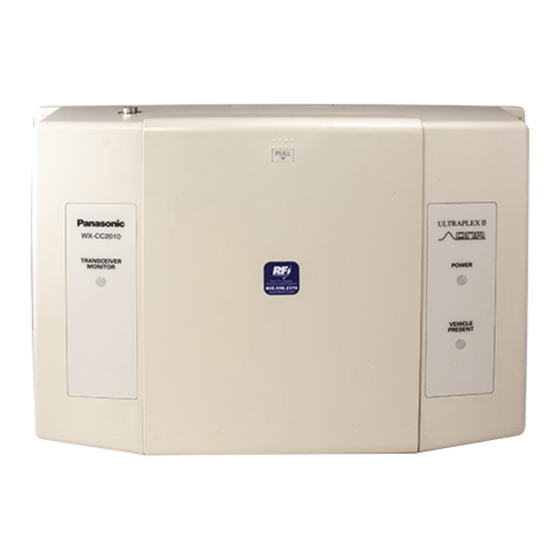
PANASONIC WX-CC2010 SERIES SYSTEM PARTS AND ACCESSORIES Note: Illustrations may differ from actual products. Center Module All in One Headset Order Taker Unit WX-CC2010 WX-CH2050 WX-CT2020 WX -CC 20 10 TR AN SC EIV MO NIT ULTRAPLEX II POWER VEHICLE... -
Page 8: Major Operating Controls And Their Functions
MAJOR OPERATING CONTROLS AND THEIR FUNCTIONS WX-CC2010 Center Module POWER VEHICLE DETECTOR CIRCUT AUX IN D.THROUGH PROTECTOR TALK MANAGER REMOTE NORMAL PAGE USA/CANADA OVERRIDE ON BEEP TBC1 LEVEL TBC2 REMOTE SP A CH SELECT LINE G/MIC AUX IN SEL DNR1 AUX OUT SEL DNR2 EFFECT... - Page 9 Notes: Talk Monitor On/Off Switch (TALK MONITOR, • The following switches and terminals should be used ON/OFF) by qualified service personnel or system installers This switch should be normally set to OFF. only. Consult your servicing dealer before attempting to •...
- Page 10 t Power On/Off Switch (POWER, ON/OFF) Noise Sound Reduction Setting Remarks This switch turns the power of the center module on Quality Level and off. No DNR processing DNR1 DNR2 DNR3 y Transceiver monitor Indicator For a relatively quiet DNR1 (TRANSCEIVER MONITOR 1 to 4) environment High...
- Page 11 !2 Remote Speaker B Volume Control In the Night mode, you will hear the beep tone of either lane in the headset if the vehicle detector is on. Once (REMOTE SP B, 0 to 10) you press the button T, you will no longer hear your This control sets the output level of Remote Speaker B lane’s beep tone.
- Page 12 @3 Menuboard Speaker B Terminals (MENU B SP 8 Ω: H, C, GND) These terminals are used for the connection with Menuboard Speaker B (Speaker Microphone WX- C550). The audio level is 8 Ω, 3 W, unbalanced. @4 Remote Speaker A Terminals (REMOTE SP A: H, GND) These terminals are used for the connection with Remote Speaker A.
-
Page 13: Wx-Ct2030 Transceiver
WX-CT2030 Transceiver WX-C1027A Headset #0 Antenna #1 Power LED Indicator #2 Center Module Connector #6 Earphone #7 Microphone #8 Cable Clips WX-C516 Power Transformer Use these clips to attach the cable to your uniform. #9 Headset Plug WX-C550 Speaker Microphone #3 Mounting Hole This hole is used for mounting the power transformer onto the wall plates. -
Page 14: Wx-Ct2020 Order Taker Unit
WX-CT2020 Order Taker Unit $5 $6 WX-CT2020 %0 %1... - Page 15 $2 Battery Lock (EJECT) $3 A/B Channel Selection Button (A/B) $4 Page Button (P) $5 Talk Button (T) $6 Power Indicator $7 Channel Indicator $8 Volume Control Buttons (VOL A B) $9 Power Button %0 Earphone Input Jack %1 Microphone Input Jack %2 Switch Pocket %3 Battery (Optional accessory)
-
Page 16: Operation Mode Descriptions
OPERATION MODE DESCRIPTIONS The following descriptions are operation modes available using WX-CC2010 Center Module and WX-CT2030 Transceiver. Notes: • "User" mentions a person using WX-CT2020 Order Taker Unit or WX-CH2050 All-in-One Headset. • When more than one user exists in the same area, the nearest user will receive the transmission signal from WX-CC2010 / WX-CT2030. -
Page 17: Operation Mode 2 (Area Expansion)
Operation Mode 2 (Area Expansion) By using WX-CT2030 Transceiver, you can expand the communication area of Operation Mode 1. • Up to three WX-CT2030 can be added. • The number of users who can simultaneously communicate in the TALK / PAGE mode depends on the total number of transceivers (WX-CC2010 x 1 + WX-CT2030 x ∗). -
Page 18: Operation Mode 3 (Manager Mode)
Operation Mode 3 (Manager Mode) In this operation mode, you can assign the role of manager / assistant personnel to each user. • The manager has the communication priority to assistant personnel. The manager can cut into a conversation with a cus- tomer even when one of assistant personnel is communicating with the customer in the TALK mode. -
Page 19: Operation Mode 4 (Area Expansion With Manager)
Operation Mode 4 (Area Expansion with Manager) By adding two WX-CT2030 Transceivers (x 1 to the assistant area and x 1 to the manager area), you can expand the commu- nication areas of Operation Mode 3. • The number of users who can simultaneously communicate in the TALK / PAGE mode depends on the total number of transceivers (WX-CC2010 x 1 + WX-CT2030 x ∗). -
Page 20: Operation Mode 5 (Double Drive Through)
Operation Mode 5 (Double Drive Through) This operation mode can be applied for a Double Drive Through composition. • The number of users who can simultaneously communicate in the TALK / PAGE mode depends on the total number of transceivers (WX-CC2010 x 1 + WX-CT2030 x ∗). Note: "∗"... -
Page 21: Operation Mode 6 (Double Drive Through With Area Expansion)
Operation Mode 6 (Double Drive Through with Area Expansion) By adding two WX-CT2030 Transceivers (x 1 to the assistant area and x 1 to the manager area), you can expand the commu- nication areas of Operation Mode 5. • The number of users who can simultaneously communicate in the TALK / PAGE mode depends on the total number of transceivers (WX-CC2010 x 1 + WX-CT2030 x ∗). -
Page 22: Operation Mode 7 (Double Drive Through With Manager Mode)
Operation Mode 7 (Double Drive Through with Manager Mode) This operation mode can be applied when you assign the role of manager / assistant personnel to each user in a Double Drive Through composition. • The number of users who can simultaneously communicate in the TALK / PAGE mode depends on the total number of transceivers (WX-CC2010 x 1 + WX-CT2030 x ∗). -
Page 23: Preparations
PREPARATIONS SW#4: For the role assignment of the person who uses the Installations and Connections order taker unit. (Refer to pp. 17, 18, and 21 for details.) Refer to qualified service personnel for details. ON: The person is assigned as a manager. OFF: The person is assigned as assistant personnel. -
Page 24: Maintenance Of Headpad Accessories (Wx-C1027A: Non-Scheduled)
2. Position the microphone boom and wear the order taker unit case as shown in the figure. Earspeaker Cover Replacement Replacement of covers and cushion of head- The earspeaker cover and microphone cover are Maintenance of Headpad washable. After cleaning, make sure they are dry. Accessories (WX-C1027A: Non- Then, return the earspeaker cover and microphone cover to the headset. -
Page 25: Operating Procedures
OPERATING PROCEDURES Refer to WX-CT2020/WX-CH2050 Operating Instructions for details. TROUBLESHOOTING Problem Check item The communication between the order taker units and menu • Is the POWER switch on the center module turned on? board cannot be established. (Refer to p. 9.) •... -
Page 26: Specifications
SPECIFICATIONS WX-CC2010 Center Module Operating Frequency: Transmit; 468.6125 MHz - 469.3875 MHz Receive; 463.6125 MHz - 464.3875 MHz Type of Emission: Type of Antenna: 1/4 wavelength whip antenna Power Supply: 12 V AC, 60 Hz (Using WX-C516 Power Transformer) Power Consumption: 18 W 3 W, 8 Ω... - Page 28 Panasonic Digital Communications & Security Company PANASONIC CANADA INC. 5770 Ambler Drive, Mississauga, Unit of Matsushita Electric Corporation of America Ontario, L4W 2T3 Canada (905)624-5010 Information Systems Group Zone Office 1707 N.Randall Road, Elgin, IL 60123 (866) 472-6767 NM0803-0 3TR001757AAA...