
Related Manuals for QSC PowerLight 6.0 II


Summary of Contents for QSC PowerLight 6.0 II
- Page 1 PowerLight 6.0 II User Manual *TD-000108-00* PowerLight Series TD-000108-00 rev.A...
-
Page 2: Important Safety Instructions
11- Only use attachments/accessories from QSC Audio Products, Inc. 12- Use only with carts, stands, tripods, brackets, interconnecting cables, or software specified by QSC Audio Products. When moving or transporting using a cart, use caution to avoid injury from tip-over. -
Page 3: Table Of Contents
Power Switch...19 Power, Standby and Protect LED indicators...19 Gain Controls...20 Signal, -20 dB, -10 dB, and Clip LED indicators...20 Clip Limiters...21 TROUBLESHOOTING...22 SPECIFICATIONS...24 APPENDIX DataPort Pinout...25 QSC PowerWave Technology Overview...26 WARRANTY INFORMATION ...27 HOW TO CONTACT QSC AUDIO PRODUCTS ...27... -
Page 4: Overview
INTRODUCTION- General Overview Thank you and congratulations on your purchase of the QSC PowerLight 6.0 II professional power amplifier. This product represents the state-of- the-art in power amplification systems for professional touring, permanent installations, and other SR (sound reinforcement) applications... -
Page 5: Illustrations
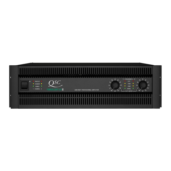
INTRODUCTION- Illustrations FRONT PANEL 1- Power switch 2- Power, Standby, and Protect LEDs 3- Cooling air exhaust vents REAR PANEL 1- Cooling air inlet vents 2- Domestic (North America) fixed AC power cord entry 2A- Export IEC-style detachable power cord entry 3- Mode switch (Bridge/Stereo/Parallel) 4- Input connectors (“combo”... -
Page 6: Unpacking
UNPACKING Unpacking and Inspection The PL6.0 II is highly durable and is carefully packaged. We recommend you inspect the unit carefully after removing it from the packaging, as occasionally there may be damage due to some unfortunate incident during shipment. Report any damage to the shipping carrier. - Page 7 SETUP- Rack Mounting Supporting the Rear of the Amplifier For mobile and touring use, it is extremely important to support the rear of the amplifier. The chassis and rack can be damaged if the amplifier is not properly supported. Unless the amplifier is being installed in its final, fixed location, QSC strongly recommends supporting the rear of the amplifier.
-
Page 8: Cooling Requirements
SETUP- Cooling Requirements Cooling Air Inlet and Exhaust Vents The PL6.0 II has four rear-mounted variable- speed fans. Fan speed is determined by the temperature of the amplifier’s internal heatsink assembly. Cooling air is drawn into the rear of the amplifier by the fans and exhausts through the front panel. -
Page 9: Ac Power Requirements
SETUP- AC Power Requirements AC Power Before connecting the amplifier to the AC mains, check the serial number plate to verify operating voltage. The PL6.0 II is available in 120 or 240 Volt models. Make sure the AC mains voltage is the same as specified on the serial number plate. -
Page 10: Operating Mode Selection
SETUP- Operating Mode Selection Operating Mode Selection The operating Mode selection switch determines how the inputs are routed to the two amplifier channels and how the outputs are connected to the speakers. The Mode selection switch is located on the rear panel, left bottom corner. - Page 11 SETUP- Operating Mode Selection Parallel Mode In Parallel Mode, the channel 1 and channel 2 input connectors are connected in parallel. Applying an input signal to either input will drive both channels. Make sure only one input signal is applied to the ampli- fier when operating in Parallel mode.
-
Page 12: Inputs
CONNECTIONS- Inputs Audio Input Connections Input connections to the PL6.0 II can be made with XLR, TRS (1/4-inch), or terminal-block connectors. The XLR/TRS connectors are “combo” style; they accept either XLR or TRS type inputs. The terminal block connectors are three-pin “Euro-”... - Page 13 CONNECTIONS- Inputs: Balanced pin 2 pin 3 pin 1 TRS (1/4-inch) Terminal-block Connectors XLR, TRS (1/4-inch), and Terminal-block Pinouts pin 2 pins 1 and 3 shield Unbalanced Jumper phone plug (tip-sleeve) shield jumper from “–” to shield...
-
Page 14: Dataport
If you are not using the PL6.0 II with QSControl, QSC DSP-3, QSC DSP-4 or other QSC DataPort accessory, do not use the DataPort. DataPort Cables Use only QSC Audio DataPort Cables for DataPort connections. Molded-connector DataPort cables are standard. Premium DataPort cables (made to... - Page 15 CONNECTIONS- DataPort (QSControl users only) Typical DataPort Application Refer to QSControl and DataPort Accessory documentation for connection details. *Required interface* Use only QSC Audio DataPort Cables for DataPort connections available from QSC’s Technical Services Group.. If amplifier Power Status is to be con-...
-
Page 16: Power Supply Remote Control
CONNECTIONS- Power Supply Control (Standby/Enable) Remotely Controlling the Amplifier’s Power Status The PL6.0 II provides two methods for remotely controlling its Power Status: 1- the Power Supply Control connection 2- the DataPort connection (using QSControl) Two status modes are possible: STANDBY and ENABLE. -
Page 17: Outputs: Binding Posts
CONNECTIONS- Outputs: Binding Posts Connecting the Outputs to the Speakers Use either the binding post or the Speakon™ output connections. Binding posts are covered on this page, Speakons on the following page. Note that the PL6.0 II does not support Bridge mode output from the Speakons (see page 11). -
Page 18: Outputs: Speakons
CONNECTIONS- Outputs: Speakon™ pinout Speakon Outputs The Speakon outputs are for use in Stereo and Parallel operating modes. Minimum speaker impedance when using Speakon connection is 4-ohms. 2-ohm load-connection to Speakon is not recommended; output power of this amplifier exceeds Speakon capability at 2-ohms. The Speakons are wired Pin 1+ = positive, Pin 1- = negative. -
Page 19: Power Switch
USE- AC Power Switch and LED Indicators AC Power Switch On the left side of the front panel is the Power switch. The switch is labeled ON, above it and to the right. To turn the power on: Press in on the upper portion of the rocker switch. -
Page 20: Gain Controls
USE- Gain Controls Gain Controls A Gain control adjustment is provided for each channel. The voltage gain of the amplifier (in dB) is marked around each control. Rotating the control clockwise increases the gain of the amplifier. Rotating the control counter- clockwise reduces the gain of the amplifier. -
Page 21: Clip Limiters
USE- Clip Limiters Clip Limiters The PL6.0 II has separate clip limiters for each channel which respond only to actual amplifier clipping. Amplifier clipping generates internal error signals which cause the Clip Limiter to quickly reduce gain and minimize the overdrive. To preserve as much of the program dynamics as possible, limiting occurs only during actual clipping. -
Page 22: Troubleshooting
Can I use some sort of adapter on the power cord so that I can use “regular” outlets?- • QSC Audio Products strongly discourages ANY changes in the AC power connections. Use only NEMA L5-30, 120V, 30 Ampere twist-lock connectors or the 240V cordset supplied with the amplifier. - Page 23 TROUBLESHOOTING I am using the amp for a subwoofer application and it sounds “rubbery”, what’s up?- • Verify that the Clip Limiters are OFF. See page 21. • The Clip Limiter is set to respond as quickly as possible after clipping is detected. On low frequency material, this may be perceived as a “rubbery”...
-
Page 24: Specifications
SPECIFICATIONS- PowerLight 6.0 II Electrical Data Output Circuit Type Output Power in watts 20 Hz to 20 kHz EIA: 1 kHz @ 1% THD Bridged Mode Dynamic Headroom at 4 ohms Distortion, THD 20 Hz to 20 kHz 20 Hz to 2 kHz... -
Page 25: Appendix
SPECIFICATIONS- PowerLight 6.0 II Electrical Data QSControl Control and Monitor Parameters Cooling Amplifier Protection Load Protection Weight Power Requirements Current Consumption 120 Volts (in amperes, rms) Current Consumption Notes: APPENDIX- DataPort Pinout The DataPort connection is QSC-specific. Informa- tion is subject to change. -
Page 26: Qsc Powerwave Technology Overview
60 Hz fields that can couple into internal or external audio circuitry. So, enjoy the brute power of the 6,000-watt PowerLight 6.0 II, you’ll enjoy premium performance at less than half the weight of conventional analog power supply amplifiers! What’s the difference between the... -
Page 27: Warranty Information
(USA only; other countries, see your dealer or distributor) Disclaimer QSC Audio Products, Inc. is not liable for any damage to speakers, or any other equipment that is caused by negligence or improper installation and/or use of this amplifier product. - Page 28 QSC Audio Products, Inc. 1675 MacArthur Boulevard Costa Mesa, California 92626 USA “QSC” and the QSC logo are registered with the U.S. Patent and Trademark Office. ©2002 QSC Audio Products, Inc.