Table of Contents
Advertisement
Advertisement
Table of Contents

Related Manuals for Apollo SA7800-870APO

Summary of Contents for Apollo SA7800-870APO
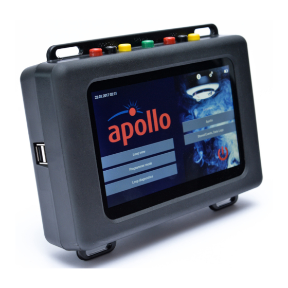
- Page 1 Apollo Test Set - User Manual Apollo Test Set User Manual...
-
Page 2: Table Of Contents
Apollo Test Set - User Manual Contents Safety first How do I use Programmer mode? Technical information Using the Programmer mode test buttons Where do I find things? Self test How do I switch the Test Set on? Fast test... -
Page 3: Safety First
• The Apollo Test Set is designed for indoor use only and should not be subjected to harsh environments. It is not designed for use in hazardous areas - those containing explosives or dust. Do not use the Test Set in places where temperatures and/or humidity are high or go through rapid changes. -
Page 4: How Do I Switch The Test Set On
Apollo Test Set - User Manual How do I switch the Test Set on? To switch the Test Set on, press and hold the green power on button on the side of the unit. When the power LED lights up you can release the power on button. -
Page 5: How Do I Control The Touchscreen
Apollo Test Set - User Manual How do I control the touchscreen? The touchscreen is controlled using a finger and swiping in different directions to select things on the screen. In this User Manual the icons that follow are used to show how to move around the touchscreen. - Page 6 Apollo Test Set - User Manual Device type test set ID Description Single Channel I/O Unit, Switch Monitor Unit, Three Channel I/O Unit and Three Channel I/O Unit (Analogue) I/O Output Units and XP95A Relay Output Module Input Unit (1 I/P, Faceplate and DIN-rail)
-
Page 7: How Do I Navigate Through The Various Menu Screens
Apollo Test Set - User Manual How do I navigate through the various menu screens? By swiping right on the left of the screen the menu selection bar appears. Tap the menu you want to move to and the main screen changes. Tap Home to return to the Home Screen. -
Page 8: Locations
Apollo Test Set - User Manual Locations The Locations section of the Settings screen enables you to: • Add a new location • Remove a location from the list • Clear all data at the selected location Alongside the location name you will find how much memory the data is taking up and two other icons;... -
Page 9: Cable Types
Apollo Test Set - User Manual Cable types The Cable types section of the Settings screen enables you to: • Add a new cable type to the list • Add new dimensions to a cable type • Remove a cable type from the list •... - Page 10 Apollo Test Set - User Manual To remove a cable type from the list, tap the delete icon alongside the cable type. A splash screen appears asking you to confirm cable removal. Tap ‘Yes’, the cable type is removed. To remove a cable dimension from the list, tap the delete icon alongside the dimension.
-
Page 11: Setting The Date And Time
Apollo Test Set - User Manual Setting the date and time The date and time are set out as shown on the left. Year Hour Month Minute To set the date and time: Tap each section, a drop-down menu appears. -
Page 12: How Do I Use The Loop View Menu
Apollo Test Set - User Manual How do I use the Loop View menu? When using the Loop View menu the device status is indicated using the colours that follow: Corrupt data Empty Dual Analogue 8 < analogue 45 ≤... -
Page 13: Selecting A Polling Range
Apollo Test Set - User Manual Whilst we are talking about the top bar lets see what the other icons mean: Direction enabled (yellow)/disabled (grey) - tap to change the current status Voltage 28 V/35V - tap the icon to switch voltages... -
Page 14: Viewing The Details Of A Single Address
Apollo Test Set - User Manual With the basics of the Loop View menu covered, let’s do a few tasks: Selecting a polling range To select a range of addresses to be polled, press and hold at the starting address, then slide your finger to the finishing address. -
Page 15: Changing The Output Bit Status
Apollo Test Set - User Manual Device address Range ID - see page Device type test set ID - see page Serial Number in HEX XXXX-XXXXXXXX (MSB to LSB) Manufacture date - first three letters of month, year Sensor status - first row, sensor type, second row live sensor status, third row last sensor status. -
Page 16: Self Test
Apollo Test Set - User Manual Changing the output bit status To change the output bit status of a particular device, tap on the required address, the single address splash screen appears. Tap the output bit icon that you want to change the status of. - Page 17 Apollo Test Set - User Manual Tap the Fast Test button, the fast test is activated immediately. If a fast test cannot be done - a message ‘Fast test cannot be performed’ appears and the splash screen returns to the single address view.
-
Page 18: Isolator Control
Apollo Test Set - User Manual Isolator control The Isolator Control button is used to switch the device isolator on or off. To switch the isolator on, tap the isolator button. As the isolator switches on the colour of the button changes to blue. -
Page 19: Mode And Polling Led
Apollo Test Set - User Manual Mode and polling LED This menu enables you to see the mode and LED status of the devices on the loop. Swipe right from the left side of the screen. The menu selection bar appears. -
Page 20: Analogue Value/Drift
Apollo Test Set - User Manual Analogue Value/Drift This menu enables you to view the analogue and drift values of the devices on the loop. Swipe right from the left side of the screen. The menu selection bar appears. Tap ‘Analogue value/Drift’. The menu selection bar closes and the Analogue value and Drift screen appears. -
Page 21: Control And Status
Apollo Test Set - User Manual Control and Status This menu enables you to view the current status of input and output bits. Swipe right from the left side of the screen. The menu selection bar appears. Tap ‘Control and Status’. The menu selection bar closes and the Control and Status screen appears. -
Page 22: Events
Apollo Test Set - User Manual Events The Events menu shows event flags, event types and event addresses. When the Events menu is selected the unit starts recording (indicated by a flashing red LED in the title bar) all events that occur. The type of event and the device status is... -
Page 23: Event Logs
Apollo Test Set - User Manual Event logs To show event logs: To see the events for an individual device. Tap on the required address. The event log appears in front of the event screen. The event log shows a list of events for the individual device. -
Page 24: Data Log
Apollo Test Set - User Manual Data log This menu gives a list of all events on the loop. This can range from mismatched data through to the current device status. When you select the data log menu the unit starts recording data logs for each individual address. Changes on each address are shown by different colours. -
Page 25: How Do I Use Programmer Mode
Apollo Test Set - User Manual How do I use Programmer mode? Programmer mode is used with the detector base provided. In this mode only CoreProtocol is used. The detector mounting base with an XPERT8 address card with a pre-defined address of 1. -
Page 26: Using The Programmer Mode Test Buttons
Apollo Test Set - User Manual Using the Programmer mode test buttons Self test Tap the Self Test button, the self test is activated immediately. The circle represents a countdown timer which is set at 20 seconds. If the analogue value increases to 55 before the timer expires, a ’Pass’... -
Page 27: Led Test
Apollo Test Set - User Manual If the device successfully passes the data restore operation, the ‘Data restored’ splash screen (a) appears. If the data restore is not successful the ‘Issue during restore operation’ splash screen appears along with details of the initial device settings (mode, polling LED status). -
Page 28: Settings
Apollo Test Set - User Manual Settings The Settings section of the programmer mode splash screen enables you to adjust the settings of a Discovery or Soteria device. The available options depend upon the type of device that is fitted to the mounting base. -
Page 29: Return To Factory Defaults
Apollo Test Set - User Manual Tap in the new soft address for the device. The splash screen then changes to show either a ‘success’ or ‘Error’ message. Success - shows that the new address has been set. Error - new address has not been set. This could be that the address is already assigned, not available on the loop or is incorrect. -
Page 30: Sounders
Apollo Test Set - User Manual Sounders Additional fields become available if a sounder is connected to the Test Set in Programmer mode. Two sounder functions are available, alert and evacuate. Tap ‘Alert’, a drop-down appears that enables you to choose between the alert and evacuate functions. -
Page 31: How Do I Use Loop Diagnostics
Apollo Test Set - User Manual How do I use Loop diagnostics? Loop diagnostics provide: • Wire connection test • Loop voltage and current measurement • Short circuit fault test • Loop cable impedance measurement • Earth fault test •... -
Page 32: Short Circuit Fault
Apollo Test Set - User Manual The first thing tested is the loop integrity. If there is a broken wire or it is not plugged into a socket, a warning message ‘Wire connection issue’ appears below the top bar. In addition it will tell you which wire is carrying the fault. -
Page 33: Cable Impedance And Cable Run
Apollo Test Set - User Manual Cable impedance and cable run When a cable run is between one and 4178 metres, cable impedance and cable run values are shown on the screen. If the cable run is either less than one... -
Page 34: Loop Supply From Direction - In
Apollo Test Set - User Manual Loop supply measurements are only possible if there are no faults on the loop. The loop is supplied with 28 V dc from OUT, coloured blue on-screen. The voltage is measured on the IN side, with the direction of current flow from OUT to IN. -
Page 35: Occupied Address Search
Apollo Test Set - User Manual Earth fault location search The earth fault location search for the automatic detection of the earth fault location on the negative loop conductor can only be done on a Soteria system with isolators. It can also only be done under certain conditions, that is, when all connections are good and there is no short circuit between the loop plus and minus wires. -
Page 36: Loop Devices Map Building
Apollo Test Set - User Manual Loop devices map building Loop devices map building function uses the Soteria isolator function to break the loop and sort. It then sorts the addresses into an ‘as fitted’ order. Progress is indicated as a percentage , but if there is an issue the process stops and a warning is shown. -
Page 37: How Do I Enter A Location
Apollo Test Set - User Manual If there is more than one earth fault detected, the result is shown as either between an address and the IN loop, or between an address and the OUT loop. To find the fault you should check the loop back from the address that is given. -
Page 38: How Do I Use Stored Events, Data Logs
Apollo Test Set - User Manual How do I use Stored Events , Data logs? If a location is entered on the Test Set, the Stored Events, Data logs tab becomes available. Tap the ‘Stored Events, Data Logs’ tab. The stored data and events screen appears. - Page 39 Apollo Test Set - User Manual To delete the report: Tap the dustbin icon. A splash screen appears asking you to confirm the deletion. Tap ‘Yes’ to delete the report, tap ‘No’ to return to the report screen. To export the report onto a USB device as a .csv file:...
-
Page 40: How Do I Update Firmware
To make sure that the Test Set operates efficiently, it may be necessary to update the firmware that operates it. Firmware updates will be made available on www.apollo-fire.co.uk and will require loading onto a USB flash drive. To install the firmware update: 1. - Page 41 (except firmware update) are disabled. The last stable firmware update version can be found at www.apollo-fire.co.uk. This stable version should be down- loaded onto the USB flash stick and the firmware update procedure repeated using this stable version.
-
Page 42: Troubleshooting
This section contains a list of potential problems and their solutions. I have pressed and held the power-on button, but the Test Set has not powered on. If the power LED is illuminated, try a hard reset. If it still does not work, contact Apollo Technical Support. -
Page 43: Appendix A - Menu Tree
Apollo Test Set - User Manual Appendix A - Menu tree The test set menu tree is constructed as follows: Self test Addresses HM Set TB Fast test Mode and Polling LED Single address view HM Set TB Isolator control Analogue value/ Configuration status... -
Page 44: Appendix B - Short Circuit And Earth Fault Detection
Apollo Test Set - User Manual Appendix B - Short circuit and earth fault detection flowchart MANAGEMENT MANAGEMENT PRODUCT SYSTEMS SYSTEMS CERTIFICATION Assessed to ISO 9001:2008 Assessed to ISO 14001:2004 Cert/LPCB ref. 010 Cert/LPCB ref. 010 Cert/LPCB ref. 010 EMS... -
Page 45: Appendix C - Loop Supply From Direction Out
Apollo Test Set - User Manual Appendix C - Loop supply from direction OUT... -
Page 46: Appendix D - Loop Supply From Direction In
Apollo Test Set - User Manual Appendix D - Loop supply from direction IN MANAGEMENT MANAGEMENT PRODUCT SYSTEMS SYSTEMS CERTIFICATION Assessed to ISO 9001:2008 Assessed to ISO 14001:2004 Cert/LPCB ref. 010 Cert/LPCB ref. 010 Cert/LPCB ref. 010 EMS... -
Page 47: Appendix E - Earth Fault Location Search
Apollo Test Set - User Manual Appendix E - Earth fault location search... -
Page 48: Appendix F - Firmware Update
Apollo Test Set - User Manual Appendix F - Firmware update MANAGEMENT MANAGEMENT PRODUCT SYSTEMS SYSTEMS CERTIFICATION Assessed to ISO 9001:2008 Assessed to ISO 14001:2004 Cert/LPCB ref. 010 Cert/LPCB ref. 010 Cert/LPCB ref. 010 EMS... -
Page 49: Appendix G - Line Voltages
Apollo Test Set - User Manual Appendix G - Line Voltages... - Page 50 Apollo Test Set - User Manual PP2625/2018/Issue 1 This page has intentionally been left blank MANAGEMENT MANAGEMENT PRODUCT SYSTEMS SYSTEMS CERTIFICATION Assessed to ISO 9001:2008 Assessed to ISO 14001:2004 Cert/LPCB ref. 010 Cert/LPCB ref. 010 Cert/LPCB ref. 010 EMS...
Need help?
Do you have a question about the SA7800-870APO and is the answer not in the manual?
Questions and answers