
Related Manuals for B&B Electronics Vlinx MESR901


Summary of Contents for B&B Electronics Vlinx MESR901
- Page 1 Manual Documentation Number MESR9xx-4210m www.bb-elec.com www.bb-europe.com...
- Page 2 International Headquarters International Headquarters B&B Electronics Mfg. Co. Inc. 707 Dayton Road Ottawa, IL 61350 USA Phone (815) 433-5100 -- General Fax (815) 433-5105 Website: www.bb-elec.com European Headquarters B&B Electronics Ltd. Westlink Commercial Park Oranmore, Co. Galway, Ireland Phone +353 91-792444 -- Fax +353 91-792445 Website: www.bb-europe.com Revision Three –...
-
Page 3: Table Of Contents
Table of Contents Introduction ............................... 1 About MESR9xx Modbus Gateways ............................1 MESR9xx Modbus Gateway Model Numbering ......................... 2 List of MESR9xx Modbus Gateway Models ..........................3 MESR9xx Modbus Gateway Features ............................4 Vlinx Manager Configuration Software ............................ - Page 4 Table of Contents Hints and Tips ..................................61 Appendices ..............................63 Appendix A: Default Gateway Settings ............................ 64 Appendix B: Product Specifications ............................65 General Specifications ..............................66 Controls, Indicators and Connector Specifications ....................67 ...
-
Page 5: Introduction
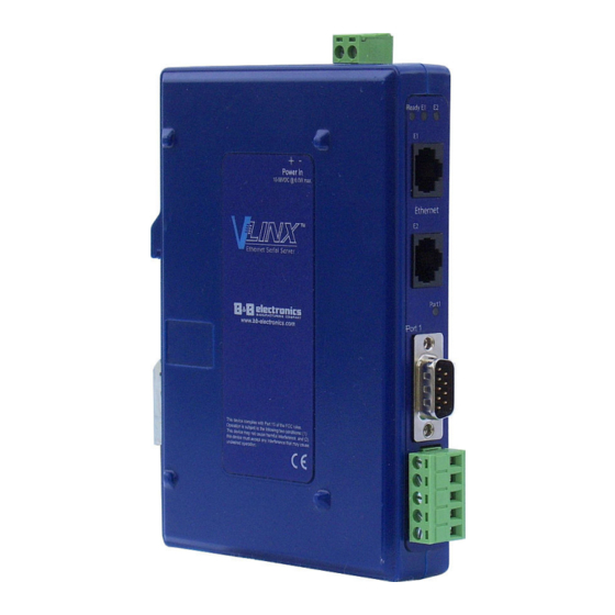
1. Introduction Vlinx MESR9xx Modbus Gateway Introduction Introduction Thank you for purchasing a MESR9xx Modbus Gateway product! This product has been manufactured to the highest standards of quality and performance to ensure your complete satisfaction. Figure 1. An MESR921 Modbus Gateway About MESR9xx Modbus Gateways MESR9xx Modbus Gateway connect Modbus networks (RS-232, RS-422 or RS-485) -
Page 6: Mesr9Xx Modbus Gateway Model Numbering
1. Introduction Vlinx MESR9xx Modbus Gateway MESR9xx Modbus Gateway Model Numbering MESR9xx Modbus Gateway are a growing family of products. Models are available with one or two serial connections. Network connection options include 10BaseT/100BaseTX copper or several different fiber optic options. The following diagram shows the model numbering scheme: Page 2 Manual Documentation Number MESR9xx-4210m... -
Page 7: List Of Mesr9Xx Modbus Gateway Models
1. Introduction Vlinx MESR9xx Modbus Gateway List of MESR9xx Modbus Gateway Models The following table lists the various MESR9xx Modbus Gateway models available. Model Serial Serial Ethernet Ethernet Ethernet Number Port(s) Connector Port(s) Media Connector(s) MESR901 DB9 & TB Copper RJ-45 MESR901-MC DB9 &... -
Page 8: Mesr9Xx Modbus Gateway Features
1. Introduction Vlinx MESR9xx Modbus Gateway Model Serial Serial Ethernet Ethernet Ethernet Number Port(s) Connector Port(s) Media Connector(s) MESR921-ST80 DB9 & TB SM Fiber (80 km) & Copper (1) RJ-45 & (1) ST MESR922T (2) Copper (2) RJ-45 MESR922T-MC MM Fiber & Copper (1) RJ-45 &... -
Page 9: Vlinx Manager Configuration Software
1. Introduction Vlinx MESR9xx Modbus Gateway • TCP Client or Server operation - configurable • Firmware Upload for future revisions/upgrades • Software Support - Windows 2000, XP (32/64 bit), 2003 Server (32/64 bit), Vista (32/64 bit), 2008 Server (32/64 bit), Windows 7 (32/64 bit) •... -
Page 10: Mesr9Xx Modbus Gateway Hardware
2. Hardware Vlinx MESR9xx Modbus Gateway MESR9xx Modbus Gateway Hardware MESR9xx Modbus Gateway Hardware MESR9xx Modbus Gateways are enclosed in DIN rail mountable enclosures and feature LED indicators, power, Ethernet and serial connectors and a recessed Mode switch. Package Checklist MESR9xx Modbus Gateways are shipped with the following items included: •... -
Page 11: Led Indicators
2. Hardware Vlinx MESR9xx Modbus Gateway LED Indicators MESR9xx Modbus Gateways have three types of LED indicators: Ethernet Link LEDs, a Ready LED and Serial Port LEDs. Figure 3. Ready Ethernet Port LEDs on 1 and 2 Ethernet Port Modbus Gateways E1/E2 Ethernet Link LED The Ethernet Link LED (E1 or E2) illuminates (green) if the Ethernet is connected. -
Page 12: Mode Switch
2. Hardware Vlinx MESR9xx Modbus Gateway Mode Switch A recessed momentary reset switch is located on the top of the enclosure. To activate the switch, insert a small plastic tool through the hole in the enclosure and press lightly. Mode Switch Figure 5. -
Page 13: Fiber Optic Connectors
2. Hardware Vlinx MESR9xx Modbus Gateway Fiber Optic Connectors Modbus gateway models using fiber optic network connections use either SC or ST connectors, depending on the specific model. Figure 7. SC and ST Fiber Optic Cable Connectors Serial Port Connectors MESR9xx Modbus Gateways use four serial port connector configurations, depending on the model: •... -
Page 14: Power Connector
2. Hardware Vlinx MESR9xx Modbus Gateway Power Connector The power connector is a 2-position pluggable terminal block. Figure 10. Power Connection Mounting Hardware MESR9xx Modbus Gateway modules can be DIN rail mounted. The DIN mounting clip and spring is included on each module. Figure 11. -
Page 15: Modbus Gateway Setup And Connections
3. Setup and Connections Vlinx MESR9xx Modbus Gateway Modbus Gateway Setup and Connections Modbus Gateway Setup and Connections Note: In this section devices to be connected to the Modbus gateway’s serial connection are simply referred to as the “Modbus network”. Connecting the Power Supply Connect a DC power supply to the power terminals on the top of the Modbus gateway. -
Page 16: Connecting The Mesr9X1-X
3. Setup and Connections Vlinx MESR9xx Modbus Gateway When configured for 2-wire operation the connection supports one signal pair: DataB(+) and DataA(-) signal channels using half-duplex operation. The data lines are differential with the Data B line positive relative to Data A in the idle (mark) state. Ground provides a common mode reference. -
Page 17: Connecting The Mesr9X2T-X
3. Setup and Connections Vlinx MESR9xx Modbus Gateway Connecting the MESR9x2T-x The MESR9x2T-x has two serial connections that support RS-232, RS-422 and RS-485 (2- and 4-wire). The unit has two connectors, both of which are 5-position terminal blocks. Make the appropriate connections to the terminal blocks to match the serial connection mode you select when configuring the Modbus gateway. -
Page 18: Connecting Mesr9Xx Modbus Gateways To A Network
3. Setup and Connections Vlinx MESR9xx Modbus Gateway Connecting MESR9xx Modbus Gateways to a Network Network Connection (10BaseT/100BaseTX) When connecting a Modbus gateway equipped with a 10BaseT/100BaseTX network connection (RJ45 connector) a standard network cable is connected from the Modbus gateway to a network drop. - Page 19 3. Setup and Connections Vlinx MESR9xx Modbus Gateway Figure 16. Modbus Gateway Manager Installation Welcome Screen b. Click “Next.” The License Agreement Screen will be displayed on your computer. Figure 17. Modbus License Acceptance Screen Page 15 Manual Documentation Number MESR9xx-4210m www.bb-elec.com/ www.bb-europe.com/...
- Page 20 3. Setup and Connections Vlinx MESR9xx Modbus Gateway c. Click “Next.” The User Information Screen will be displayed on your computer. Enter your name and organization (optional) and select if the software will be accessible to your account or anyone who uses the computer. Figure 18.
- Page 21 3. Setup and Connections Vlinx MESR9xx Modbus Gateway e. Click “Next.” The Ready to Install Application Screen will be displayed on your computer. You can select the “Back” button to change destination folder. Figure 20. Ready to Install Application Screen f.
- Page 22 3. Setup and Connections Vlinx MESR9xx Modbus Gateway g. After the installation is complete, an information screen will be displayed containing contact information and release notes. Click “Next.” Figure 22. Information Screen h. Click “Next.” The Installation Complete screen will be displayed on your computer.
-
Page 23: Configuring The Mesr9Xx Modbus Gateway Via The Network Connection
3. Setup and Connections Vlinx MESR9xx Modbus Gateway Configuring the MESR9xx Modbus Gateway via the Network Connection When configuring via the network, either Modbus Configuration software or the web interface can be used. Configuring with Modbus Configuration Manager MESR9xx Modbus Gateways can be configured over the network Modbus Configuration manager software running on a PC. - Page 24 3. Setup and Connections Vlinx MESR9xx Modbus Gateway 2. The Vlinx Modbus Configuration Manager Device Discovery window appears. Figure 26. Vlinx Modbus Configuration Manager Discovery Window 3. If you do not know the IP address, check the “Network” and “I don’t know the IP address of this device”...
- Page 25 3. Setup and Connections Vlinx MESR9xx Modbus Gateway 4. All Modbus Gateways on the network will be displayed in the top portion of the screen. To select a gateway, simply click the appropriate device on the top portion of the screen. a.
- Page 26 3. Setup and Connections Vlinx MESR9xx Modbus Gateway d. This area contains helpful information about the configuration screen you are currently on. e. This area contains shortcuts to specific functions. 1. Open allows you to load a previously saved configuration file into your Modbus Gateway.
- Page 27 3. Setup and Connections Vlinx MESR9xx Modbus Gateway a. This screen enables you to assign a unique name to the gateway. This allows you to easily identify a particular gateway when multiple devices are used on the same network. To change the name, type a new name in the “The Name of this Modbus Gateway is”...
- Page 28 3. Setup and Connections Vlinx MESR9xx Modbus Gateway 8. Network Settings a. To get to the Network Settings Screen you can either click the “Next Button” or click on the “Network” link on the left side of the screen. Figure 31. Network Settings Screen (DHCP Selected) b.
- Page 29 3. Setup and Connections Vlinx MESR9xx Modbus Gateway For Class B network (IP addresses 128.0.0.0 through 191.255.255.255), the default subnet mask is 255.255.0.0. For Class C network (IP addresses 192.0.0.0 through 223.255.255.255), the default subnet mask is 255.255.255.0. For Class D network (IP addresses 224.0.0.0 through 239.255.255.255) and Class E network (IP addresses 240.0.0.0 through 255.255.255.255), the subnet mask is ignored.
- Page 30 3. Setup and Connections Vlinx MESR9xx Modbus Gateway Figure 33. Modbus TCP Settings Screen c. TCP Client Settings 1. Connect to Port identifies TCP port to be used by the Modbus Gateway in TCP client mode. Valid value range is from 1 to 65535. 2.
- Page 31 3. Setup and Connections Vlinx MESR9xx Modbus Gateway a. You can select “allow specific IP addresses to connect.” This filter is limited to 4 IP addresses. Figure 34. TCP Connection Filter “Allow Specific IP addresses to Connect b. You can select “a specific range of IP addresses to connect.”...
- Page 32 3. Setup and Connections Vlinx MESR9xx Modbus Gateway Figure 35. TCP Connection Filter “Allow Specific Range of IP Addresses to Connect 10. PORT x Serial Settings a. To access this screen, click the “Next” button or click the Port X Serial link on the left side of the screen.
- Page 33 3. Setup and Connections Vlinx MESR9xx Modbus Gateway a. To access this screen, click the “Next” button or click the “Port X Modbus” Link on the left side of the screen. X = The Serial Port Number (1 or 2). b.
- Page 34 3. Setup and Connections Vlinx MESR9xx Modbus Gateway h. Modbus Serial Retires – Select 0 through 5. This sets the maximum number of times that the Modbus gateway will retry to send a Modbus message to a Modbus client, before reporting a 0Bh exception if it is selected. Number of retries is limited to 5.
- Page 35 3. Setup and Connections Vlinx MESR9xx Modbus Gateway e. The third box in line is the starting ID of a range to remap to. Valid value range is from 1 to 255. f. The fourth box in line is auto filled in based on the range filled in the first 3 boxes.
- Page 36 3. Setup and Connections Vlinx MESR9xx Modbus Gateway a. To access this screen, click the “Next” button or click the “Modbus Priority” link on the left side of the screen. b. This screen allows you to configure the gateway to move high priority messages to the front of the serial message buffer.
- Page 37 3. Setup and Connections Vlinx MESR9xx Modbus Gateway Note: For more information on configuration options refer to Section 4: Description of Modbus gateway Properties. Configuring with the Web Interface MESR9xx Modbus Gateways can be configured over the network using a standard internet browser such as Internet Explorer or Firefox.
-
Page 38: Configuring The Mesr9Xx Modbus Gateway On Networks Without A Dhcp Server
3. Setup and Connections Vlinx MESR9xx Modbus Gateway Note: Your Modbus gateway comes from the factory pre-configured to receive an IP address assignment from a DHCP server. If a DHCP Server is not available on your network, it will default to 169.254.102.39. - Page 39 3. Setup and Connections Vlinx MESR9xx Modbus Gateway b. Click on Internet Protocol (TCP/IP) and click <properties>. Change the parameters to the following: IP Address = 169.254.102.1 Subnet Mask = 255.255.0.0 Default Gateway = 169.254.102.100 c. Use the Vlinx™ Modbus Manager Software to search for, discover, and configure the Modbus Gateway.
- Page 40 3. Setup and Connections Vlinx MESR9xx Modbus Gateway 2. Method 2: Change the Modbus Gateway’s network settings to match your PC using Console Mode a. Connect a null modem serial cable (crossover cable) from port 1 on the Modbus Gateway to an available COM port on your PC. b.
-
Page 41: Configuring The Mesr9Xx Modbus Gateway Via The Serial Port (Console Mode)
3. Setup and Connections Vlinx MESR9xx Modbus Gateway j. Save the settings and remove power from the Modbus Gateway. k. Re-apply power. Open the Vlinx™ Modbus Manager Software and select “Network” as the method to connect to the device. Configuring the MESR9xx Modbus Gateway via the Serial Port (Console Mode) Your Modbus gateway can be configured via a serial port using Vlinx Modbus Manager. - Page 42 3. Setup and Connections Vlinx MESR9xx Modbus Gateway Figure 45. Connection 2. If you do not know which COM port your gateway is connect to, select “Search all serial ports for the device” under Serial Port Options. If you do know, you may specify the COM port by selecting “The device is connected to this serial port”...
-
Page 43: Mesr9Xx Modbus Gateway Operational Connections
3. Setup and Connections Vlinx MESR9xx Modbus Gateway To exit Console Mode, press and hold the Reset switch for two seconds. The LEDs go back to their normal states when the device resumes normal operation. MESR9xx Modbus Gateway Operational Connections MESR9xx Modbus Gateways can operate in Direct IP Mode. -
Page 44: Initiating A Hardware Reset On The Modbus Gateway
3. Setup and Connections Vlinx MESR9xx Modbus Gateway Initiating a Hardware Reset on the Modbus Gateway To initiate a Hardware Reset on the Modbus gateway, press and hold the Mode switch for 0 to 2 seconds, and then release it. The LED indicators respond as follows: 1. -
Page 45: Upgrading The Modbus Gateway Firmware
5. Upgrading Firmware Vlinx MESR9xx Modbus Gateway Occasionally, updated firmware may become available for your Modbus gateway. The firmware can be upgraded using the Zlinx Manager software. The following procedure describes the firmware updating process: 1. Click the Upgrade button to open the Firmware Upgrade dialog box. -
Page 46: Downloading Firmware Files
5. Upgrading Firmware Vlinx MESR9xx Modbus Gateway Information about the selected firmware file is shown in the third text box. Downloading Firmware Files The Firmware File list (second box) displays all firmware files in the firmware installation folder. Only firmware that is compatible with the selected Modbus gateway is available in this list. -
Page 47: Diagnostics
6. Diagnostics Vlinx MESR9xx Modbus Gateway Diagnostics Diagnostics Diagnostics Clicking the Diagnostics icon opens the dialog box and enables you to check the operation of connected Modbus gateways on the local computer. The Computer Information box displays information about the type of network connections, the IP addresses, Subnet Masks and Default Gateways in use. - Page 48 6. Diagnostics Vlinx MESR9xx Modbus Gateway 2. In the drop down box select the specific Modbus gateway you want to check. 3. Click the Start button Test Information about the progress of the pinging process is displayed in the Progress box.
-
Page 49: Application Examples
8. Modbus Help Vlinx MESR9xx Modbus Gateway Application Examples Application Examples Modbus gateways can be used to integrate Modbus networks in a wide variety of settings. But as each setting has its own requirements, users may not understand how a gateway helps, or if it’s appropriate for their specific needs. - Page 50 8. Modbus Help Vlinx MESR9xx Modbus Gateway 1. Log into your gateway. 2. Access the serial port one setup screen by clicking the link on the left side of the screen. Figure 52. Serial Port 1 Setup 3. Configure Serial Port 1. In this case it is RS-232, 19.2 kbps, 8 data bits, 1 stop bit, and even parity.
- Page 51 8. Modbus Help Vlinx MESR9xx Modbus Gateway Figure 53. Port 1 Modbus 5. Configure the Port 1 Modbus Settings. In this case Attached should be slaves, Modbus should be RTU. The other settings depend on your application. 6. Configure Port 2 Serial and Modbus is the same fashion. 7.
- Page 52 8. Modbus Help Vlinx MESR9xx Modbus Gateway Figure 54. Port x Modbus Slave ID Remapping 8. Access Modbus ID Routing. Configure as necessary. In this example, Slave ID 200 is mapped to serial port 1, Slave ID 1 through 5 and 205 are mapped to serial port 2. Page 48 Manual Documentation Number MESR9xx-4210m www.bb-elec.com/...
- Page 53 8. Modbus Help Vlinx MESR9xx Modbus Gateway Figure 55. Modbus ID Routing 9. Access Modbus Priority and configure as necessary. Page 49 Manual Documentation Number MESR9xx-4210m www.bb-elec.com/ www.bb-europe.com/...
- Page 54 8. Modbus Help Vlinx MESR9xx Modbus Gateway Figure 56. Modbus Priority Page 50 Manual Documentation Number MESR9xx-4210m www.bb-elec.com/ www.bb-europe.com/...
-
Page 55: Serial & Ethernet Masters, Serial & Ethernet Slaves
8. Modbus Help Vlinx MESR9xx Modbus Gateway Serial & Ethernet Masters, Serial & Ethernet Slaves Your Modbus Gateway can also integrate multiple master devices onto serial and Ethernet Networks. Figure 57. Serial & Ethernet Masters, Serial & Ethernet Slaves 1. In this example, Serial Port 1 has an RTU Master attached. Configure the serial port settings as appropriate for the device. - Page 56 8. Modbus Help Vlinx MESR9xx Modbus Gateway Figure 58. Port 1 Modbus 2. Configure the Modbus Slave ID routing. In this case Modbus Slaves 1 through 5 and 205 are on Serial Port 2. Modbus Slaves 150 and 151 through 160 have IP assignments.
-
Page 57: Serial Masters, Ip Slaves
8. Modbus Help Vlinx MESR9xx Modbus Gateway Figure 59. Modbus Slave ID Routing Serial Masters, IP Slaves Serial Masters can be used to control IP Slaves. Figure 60. Serial Masters, IP Slaves Page 53 Manual Documentation Number MESR9xx-4210m www.bb-elec.com/ www.bb-europe.com/... - Page 58 8. Modbus Help Vlinx MESR9xx Modbus Gateway 1. In this example, and ASCII Master is connected to Serial Port 1 and an RTU Master is connected to Serial Port 2. Configure the serial ports as appropriate for these devices. Figure 61. Port 1 Serial Page 54 Manual Documentation Number MESR9xx-4210m www.bb-elec.com/...
- Page 59 8. Modbus Help Vlinx MESR9xx Modbus Gateway Figure 62. Port 2 Serial 2. Access the Modbus screen for each port and configure as appropriate. In this case, Port 1 has an ASCII Master and Port 2 has an RTU Master attached. Page 55 Manual Documentation Number MESR9xx-4210m www.bb-elec.com/...
- Page 60 8. Modbus Help Vlinx MESR9xx Modbus Gateway Figure 63. Port 1 Modbus Page 56 Manual Documentation Number MESR9xx-4210m www.bb-elec.com/ www.bb-europe.com/...
- Page 61 8. Modbus Help Vlinx MESR9xx Modbus Gateway Figure 64. Port 2 Modbus 3. Setup the Slave ID Routing to associate IP addresses with the appropriate Slave ID. Page 57 Manual Documentation Number MESR9xx-4210m www.bb-elec.com/ www.bb-europe.com/...
- Page 62 8. Modbus Help Vlinx MESR9xx Modbus Gateway Figure 65. Modbus Slave ID Routing Page 58 Manual Documentation Number MESR9xx-4210m www.bb-elec.com/ www.bb-europe.com/...
-
Page 63: Identical Hard Coded Slaves
8. Modbus Help Vlinx MESR9xx Modbus Gateway Identical Hard Coded Slaves In this example, two slave devices that are hard coded with the same ID are required. This is accomplished by putting them on different serial ports. Figure 66. Identical Hard Coded Slaves Page 59 Manual Documentation Number MESR9xx-4210m www.bb-elec.com/... -
Page 64: Identical Production Lines
8. Modbus Help Vlinx MESR9xx Modbus Gateway Identical Production Lines In this example, identical or backup production lines can be controlled by the same IP Master. This allows the duplicate networks to be configured identically, saving documentation and maintenance time. Figure 67. -
Page 65: Modbus Help
8. Modbus Help Vlinx MESR9xx Modbus Gateway 7. Modbus He 7. Modbus He Modbus ASCII/RTU Basics The Modbus protocol emerged in the mid-1970s as an early protocol for linking terminals with Modicon PLCs using a master/slave (sometimes called a master/client) relationship. A simple, open, message-based protocol, it caught on quickly and became a de facto standard in the industry. - Page 66 8. Modbus Help Vlinx MESR9xx Modbus Gateway • Slowing down the polling rate may be helpful if power cycling doesn’t cure the problem. • A common misperception is that every serial network must terminate with a resistor. While this was true of early serial network configurations, it’s typically the wrong answer –...
-
Page 67: Appendices
9. Appendices Vlinx MESR9xx Modbus Gateway . Appendices . Appendices This section includes the following Appendices: • Appendix A: Default Gateway Settings • Appendix B: Product Specifications • Appendix C: Dimensional Diagrams • Appendix D: Connector Pinouts Page 63 Manual Documentation Number MESR9xx-4210m www.bb-elec.com/ www.bb-europe.com/... -
Page 68: Appendix A: Default Gateway Settings
9. Appendices Vlinx MESR9xx Modbus Gateway Appendix A: Default Gateway Settings Setting Default Value Gateway Name User assigned Password password field is blank from factory DHCP Enabled IP Address DHCP will configure. If a DHCP Server is not available, the unit will default to 169.254.102.39 Net Mask 255.255.0.0... -
Page 69: Appendix B: Product Specifications
9. Appendices Vlinx MESR9xx Modbus Gateway Appendix B: Product Specifications This section includes the following specifications: • General Specifications • Controls, Indicators and Connector Specifications • Serial Interface Specifications • Network Specifications Page 65 Manual Documentation Number MESR9xx-4210m www.bb-elec.com/ www.bb-europe.com/... -
Page 70: General Specifications
9. Appendices Vlinx MESR9xx Modbus Gateway General Specifications Hardware and MESR901-x, MESR902D-x or Device included accessories MESR902T-x Modbus gateway module CD with Vlinx Modubs Manager software for Windows 2000, XP (32/64 bit), 2003 Server (32/64 bit), Vista (32/64 bit), 2008 Server (32/64 bit), Windows 7 (32/64 bit) 232NM9 Null Modem Crossover Cable for Optional Accessories... -
Page 71: Controls, Indicators And Connector Specifications
9. Appendices Vlinx MESR9xx Modbus Gateway Terminal Blocks Wire Size 28 to 16 AWG Wire Type Copper Wire Only Tightening Torque 5 KG-cm Wire Temp Rating 105°C Minimum, Sized for 60°C Ampacity Note One conductor per terminal Controls, Indicators and Connector Specifications Hold in for 0 to 2 seconds for hardware reset Hold in for 2 to 10 seconds for Console... -
Page 72: Serial Interface Specifications
9. Appendices Vlinx MESR9xx Modbus Gateway Serial Interface Specifications Mode Selection RS-232/422/485 software selectable RS-232 lines TXD, RXD, RTS, CTS, DTR, DSR, DCD, GND RS-422 lines TXDA(-), TXDB(+), RXDA(-), RXDB(+), GND RS-485 lines (2 wire) Data(-), Data(+), GND RS-485 lines (4 wire) TXDA(-), TXDB(+), RXDA(-), RXDB(+), GND 75, 150, 300, 600, 1200, 2400, 4800, 7200, Baud Rates... -
Page 73: Network Specifications
9. Appendices Vlinx MESR9xx Modbus Gateway Network Specifications Memory Serial Memory 10 K bytes per port Network Memory 10 K bytes I/P Port Addresses 5300 Configuration setting in TCP Mode 8888 MESR9xx update Network 10/100 Mbps Auto-detecting 10BaseT or Communications 100BaseTX Network Physical IEEE 802.3 auto-detecting &... -
Page 74: Appendix C: Dimensional Diagrams
9. Appendices Vlinx MESR9xx Modbus Gateway Appendix C: Dimensional Diagrams Figure 68. Dimensional Diagram of an MESR901 Modbus Gateway (Note: Small Case Used for MESR901 Series Units) Page 70 Manual Documentation Number MESR9xx-4210m www.bb-elec.com/ www.bb-europe.com/... - Page 75 9. Appendices Vlinx MESR9xx Modbus Gateway Figure 69. Dimensional Diagram of an MESR902T Modbus Gateway (Note: Small Case Used for MESR902 Series Units) Page 71 Manual Documentation Number MESR9xx-4210m www.bb-elec.com/ www.bb-europe.com/...
- Page 76 9. Appendices Vlinx MESR9xx Modbus Gateway Figure 70. Dimensional Diagram of an MESR921 Modbus Gateway, Left and Right Side Views (Note: Medium Case Used for MESR921 and MESR922 Series Units) Page 72 Manual Documentation Number MESR9xx-4210m www.bb-elec.com/ www.bb-europe.com/...
- Page 77 9. Appendices Vlinx MESR9xx Modbus Gateway Figure 71. Dimensional Diagram of an MESR921 Modbus Gateway, Bottom, Top, Back and Front Views (Note: Medium Case Used for MESR921 and MESR922 Series Units) Page 73 Manual Documentation Number MESR9xx-4210m www.bb-elec.com/ www.bb-europe.com/...
-
Page 78: Appendix D: Connector Pinouts
9. Appendices Vlinx MESR9xx Modbus Gateway Appendix D: Connector Pinouts MESR901-x Serial Port Pinouts DB9 M Pin Direction RS-232 Input Input Output Output Input Output Input Input Page 74 Manual Documentation Number MESR9xx-4210m www.bb-elec.com/ www.bb-europe.com/... - Page 79 9. Appendices Vlinx MESR9xx Modbus Gateway Terminal RS-422/485 4-Wire RS-485 2-Wire TDA (-) Data A (-) TDB (+) Data B (+) RDA (-) RDB (+) Page 75 Manual Documentation Number MESR9xx-4210m www.bb-elec.com/ www.bb-europe.com/...
-
Page 80: Mesr902T-X Serial Port Pinouts
9. Appendices Vlinx MESR9xx Modbus Gateway MESR902T-x Serial Port Pinouts Terminal RS-232 Direction (RS-232) RS-422 RS-485 Output TDA (-) Data A (-) Output TDB (+) Data B (+) Input RDA (-) Input RDB (+) In the RS-422 mode, TX lines are outputs and RX lines are inputs. Connect the Modbus gateway TXB(+) line to the RXB(+) line of the Modbus network, and the Modbus gateway TXA(-) to the RXA(-) of the Modbus network. -
Page 81: Standard Ethernet Cable Rj-45 Pin-Out
9. Appendices Vlinx MESR9xx Modbus Gateway Standard Ethernet Cable RJ-45 Pin-out RJ-45 Pin Signal Wire Color White-Green Green White-Orange Not used Blue Not used White-Blue Orange Not used White-Brown Not used Brown Page 77 Manual Documentation Number MESR9xx-4210m www.bb-elec.com/ www.bb-europe.com/... -
Page 82: Glossary
10. Glossary Vlinx MESR9xx Modbus Gateway 9. Glossary 9. Glossary Term Definition ADU Application Data Unit ASCII American Standard Code for Information Interchange Baud Rate Number of bits per second CRC Cyclical Redundancy Checking Number of bits per byte, normally 7 with Modbus ASCII, and 8 with Data Bits Modbus RTU DHCP Dynamic Host Configuration Protocol... - Page 83 10. Glossary Vlinx MESR9xx Modbus Gateway Term Definition Interface between Data Terminal Equipment and Data Circuit-Terminating RS-232 Equipment Employing Serial Binary Data Interchange Electrical Characteristics of Generators and Receivers for Use in Balanced RS-422 Digital Point to Point Systems Electrical Characteristics of Generators and Receivers for Use in Balanced RS-485 Digital Multipoint Systems RTU Remote Terminal Unit...
Need help?
Do you have a question about the Vlinx MESR901 and is the answer not in the manual?
Questions and answers