Table of Contents
Advertisement
Advertisement
Table of Contents

Related Manuals for Leeson 174475


Summary of Contents for Leeson 174475
- Page 1 ® SPEEDMASTER MICRO SERIES COMPACT INVERTERS Installation and Operation Manual...
- Page 2 EC Declaration of Conformity...
-
Page 3: Table Of Contents
TABLE OF CONTENTS GENERAL ............PRODUCT CHANGES . -
Page 4: General
Contact Leeson’s Warranty Dept. for a return authorization number and shipping instructions. LEESON Electric reserves the right to make the final determination as to the validity of a warranty claim, and sole obligation is to repair or replace only components which have been rendered defective due to faulty material or workmanship. -
Page 5: Micro Series Specifications
MICRO SERIES SPECIFICATIONS Storage Temperature -20° to 70° C Ambient Operating Temperature Chassis -10° to 55° C (With 2.5 and 8 kHZ carrier, Type 1 (IP 31) -10° to 50° C derate for higher carriers) Type 4 (IP 65) -10° to 40° C Type 12 (IP 54) -10°... -
Page 6: Micro Series Dimensions
MICRO SERIES DIMENSIONS TYPE 1 ENCLOSED Conduit Holes: IF W ≤ 7.86" S Dia. T = 0.20" 0.88" Dia. 1.00" U = 0.34" S Dia. V = 0.19" IF W ≥ 10.26" T = 0.28" Dia. Slot U = 0.44" V = 0.24"... - Page 7 Conduit Holes: IF W ≤ 7.86" S Dia. T = 0.20" 0.88" Dia. U = 0.34" 1.00" V = 0.19" S Dia. IF W ≤ 10.26" T = 0.28" Dia. Slot U = 0.44" V = 0.24" Mounting Tab Detail INPUT CATALOG (kW)
- Page 8 7.86 4.90 4.80 3.25 1.37 5.88 0.88 (1.1) 174517** 240/200 174482 7.88 6.12 5.25 3.06 3.60 1.37 5.88 0.88 174529** 174475 7.88 7.86 4.90 4.80 3.25 1.37 5.88 0.88 (1.5) 174525** 240/200 174937 7.88 7.86 4.90 4.80 3.25 1.37 5.88 0.88...
- Page 9 Conduit Holes: IF W ≤ 7.86" S Dia. T = 0.20" 0.88" Dia. U = 0.34" 1.00" V = 0.19" S Dia. IF W ≤ 10.26" T = 0.28" Dia. Slot U = 0.44" V = 0.24" Mounting Tab Detail INPUT CATALOG (kW)
- Page 10 Conduit Holes: IF W ≤ 7.86" S Dia. T = 0.20" 0.88" Dia. U = 0.34" 1.00" V = 0.19" S Dia. IF W ≤ 10.26" T = 0.28" Dia. Slot U = 0.44" V = 0.24" Mounting Tab Detail INPUT CATALOG (kW)
-
Page 11: Micro Series Ratings
21.0/10.4 5.2/5.2 174517** INPUT OUTPUT MODEL (200/240 Vac, 50-60 Hz) (0-200/230 Vac) 174933 174475* 17.1/14.9 7.8/6.8 174525** 174934 174729* 24/21 11.0/9.6 174526** NOTE 1: For 115/230 Vac, the higher current rating is for 120 Vac input and the lower current rating is for 240 Vac input. - Page 12 230 VOLT MICRO SERIES RATINGS INPUT OUTPUT MODEL (200/240 Vac, 50-60 Hz) (0-200/230 Vac) FOR MOTORS NOMINAL NOMINAL CATALOG RATED INPUT CURRENT POWER CURRENT POWER NUMBER PHASE (AMPS) (KVA) (AMPS) (KVA) 174914 174935* 0.37 3.1/2.7 2.5/2.2 0.88 174527** 174915 174936* 0.75 5.5/4.8 4.6/4.0...
- Page 13 460 VOLT MICRO SERIES RATINGS INPUT OUTPUT MODEL (400/480 Vac, 50-60 Hz) (0-400/460 Vac) FOR MOTORS NOMINAL NOMINAL CATALOG RATED INPUT CURRENT POWER CURRENT POWER NUMBER PHASE (AMPS) (KVA) (AMPS) (KVA) 174920 174939* 0.75 2.8/2.4 2.3/2.0 174532** 174921 174940* 4.7/4.1 3.9/3.4 174533** 174922...
- Page 14 575 VOLT MICRO SERIES RATINGS INPUT OUTPUT MODEL (480/590 Vac, 50-60 Hz) (0-460/575 Vac) FOR MOTORS NOMINAL NOMINAL CATALOG RATED INPUT CURRENT POWER CURRENT POWER NUMBER PHASE (AMPS) (KVA) (AMPS) (KVA) 174925 174943* 0.75 1.9 / 1.9 1.6 / 1.6 174536** 174926 174944*...
-
Page 15: Theory
THEORY DESCRIPTION OF AC MOTOR OPERATION Three phase AC motors are comprised of two major components, the stator and the rotor. The stator is a set of three electrical windings held stationary in the motor housing. The rotor is a metal cylinder, fixed to the motor drive shaft, which rotates within the stator. - Page 16 If the frequency applied to the motor is increased while the voltage remains constant, torque capability will decrease as speed increases. This will cause the horsepower capability of the motor to remain approximately constant. Motors run in this mode when operated above base speed, where drive output voltage is limited by the input line voltage.
-
Page 17: Drive Function Description
"Variable torque" refers to the fact that the torque required varies with the square of the speed. Also, the horsepower required varies with the cube of the speed, resulting in a large reduction in horsepower for even a small reduction in speed. It is easily seen that substantial energy savings can be achieved by reducing the speed of a fan or pump. - Page 18 6.2.3 MC1000 INPUTS AND OUTPUTS The drive has two analog inputs (0-10 VDC and 4-20 mA) that can be used for speed reference, PID setpoint reference, or PID feedback. A speed potentiometer (10,000 Ohm) can be used with the 0-10 VDC input.
- Page 19 The following describes the possible relay output settings: NONE This setting disables the relay output. The relay energizes when the drive is given a START command, and remains energized until: a STOP command is given and the output frequency has decelerated to 0.5 Hz, the drive has "tripped", or the input voltage is removed.
-
Page 20: Installation
SUBJECTED TO: COMBUSTIBLE, OILY, OR HAZARDOUS VAPORS OR DUST; EXCESSIVE MOISTURE OR DIRT; STRONG VIBRATION; EXCESSIVE AMBIENT TEMPERATURES. CONSULT LEESON FOR MORE INFORMATION ON THE SUITABILITY OF A DRIVE TO A PARTICULAR ENVIRONMENT. The drive should be mounted on a smooth vertical surface capable of safely supporting the unit without vibrating. - Page 21 AC inverter products in these applications. The purchaser expressly agrees to assume all risk of any loss, cost, or damage that may arise from such application. LEESON Electric or LEESON Electric's engineering department will not knowingly approve applications involving...
-
Page 22: Input Ac Requirements
INPUT AC REQUIREMENTS WARNING Hazard of electrical shock. Disconnect incoming power and wait three minutes before servicing the drive. Capacitors retain charge after power is removed. INPUT AC POWER REQUIREMENTS 8.1.1 VOLTAGE: The input voltage must match the drive's nameplate voltage rating. Voltage fluctuation must not vary by greater than 10% overvoltage or 15% undervoltage. -
Page 23: Voltage Selection
Input fusing and a power disconnect switch or contactor MUST be wired in series with terminals L1, L2, and L3 (L1 and L2 if input is single phase). If one has not been supplied by LEESON Electric, a disconnect means must be wired during installation. This disconnect must be used to power down the drive when servicing, or when the drive is not to be operated for a long period of time, but should not be used to start and stop the motor. -
Page 24: Micro Series Power Wiring Diagram
Wire the motor for the proper voltage per the output rating of the drive. Motor wires MUST be run in a separate steel conduit away from control wiring and incoming AC power wiring. Do not install contactors between the drive and the motor without consulting LEESON for more information. Failure to do so may result in drive damage. -
Page 25: Initial Power Up
12.0 INITIAL POWER UP Hazard of electrical shock. Disconnect incoming power and wait three minutes before servicing WARNING the drive. Capacitors retain charge after power is removed. Before attempting to operate the drive, motor, and driven equipment be sure all procedures pertaining to installation and wiring have been properly followed. -
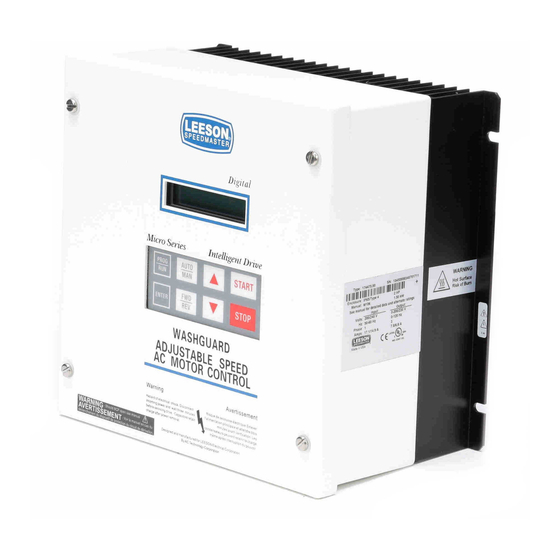
Page 26: Keypad Control
13.0 KEYPAD CONTROL The drive can be operated in a number of different ways: keypad (LOCAL), control devices wired to the terminal strip (REMOTE), or a combination of the terminal strip and the keypad. The drive should first be operated from the keypad during initial start-up. Refer to Sections 14.0 - CONTROL WIRING, and 18.0 - DESCRIPTION OF PARAMETERS for information on remote operation. -
Page 27: Micro Series Display
13.2 MICRO SERIES DISPLAY The following describes the possible display configurations for the SPEEDMASTER MICRO Series drive. 13.2.1 MICRO SERIES DISPLAY IN STOP MODE When the drive is in the STOP mode, there are three possible delays. The first is the SPEED display, which looks like this: NOTE: See Parameter 31 - HZ UNITS for the SPEED UNITS display options. - Page 28 The following table shows the possible DRIVE STATUS indications that can appear on the drive display: DRIVE STATUS TABLE DISPLAY DESCRIPTION STOP Drive is in STOP mode - No output to the motor. Drive is in RUN mode and is within + /- 3 Hz of the speed setpoint. FAULT Drive has shut down due to a FAULT condition.
- Page 29 13.2.2 MICRO SERIES DISPLAY IN RUN MODE When the drive is in the RUN mode, the default display will look like this: As in the STOP mode, the ENTER key can be used to toggle the display from SPEED to % LOAD to VAC (motor voltage): NOTE: During acceleration and deceleration to the SPEED SETPOINT, the DRIVE STATUS will show the actual drive speed.
- Page 30 13.2.3 MICRO SERIES DISPLAY IN FAULT MODE When the drive trips on a fault, the display will automatically change to the FAULT display, which indicates the FAULT MESSAGE: In FAULT mode, the ENTER key will toggle the display between four screens: FAULT, SPEED, % LOAD and VAC.
- Page 31 The table below shows the possible SPEED REFERENCE SOURCE indications for the auxiliary status display: SPEED REFERENCE TABLE DISPLAY DESCRIPTION KEYPAD - UP and DOWN arrow keys 0 - 10 VDC analog input at TB-5A 4 - 20 mA analog input at TB-5B SP#1 PRESET SPEED #1 SP#2...
-
Page 32: Control Wiring
14.0 CONTROL WIRING 14.1 GENERAL 14.1.1 KEYPAD CONTROL The drive can be controlled by the keypad or by control devices wired to the terminal strip. The drive will run from the keypad "out of the box", requiring no connections to the terminal strip. Refer to Section 13.0 - KEYPAD CONTROL. -
Page 33: Start/Stop And Speed Control
14.2 START/STOP AND SPEED CONTROL 14.2.1 REMOTE MODE SELECTION The REMOTE mode can be selected by one of two methods: Program Parameter 30 - CONTROL to REMOTE, or: Program CONTROL to BOTH, set the TB-13A or TB-13C function (see Parameter 47 or 49) to LOCAL SELECT, and DO NOT make a contact closure between TB-13A or TB-13C and TB-2 (making the contact closure will select LOCAL mode). - Page 34 14.2.3 ALTERNATE TWO-WIRE START/STOP CONTROL METHOD WARNING This method requires TB-13C to be set for RUN REVERSE, which will disable TB-1 as a STOP switch! Incorrect use of TB-1 may result in damage to equipment and/or injury to personnel! Refer to Parameter 49 - TB-13C. FORWARD ROTATION ONLY Select REMOTE mode (see 14.2.1).
- Page 35 14.2.4 THREE-WIRE START/STOP CONTROL A three-wire start/stop circuit can be accomplished by one of two methods on the MICRO Series drive. Follow the appropriate procedure listed below: FORWARD ROTATION ONLY Select REMOTE mode (see 14.2.1). Wire a normally closed momentary STOP contact between TB-1 and TB-2.Momentarily open this contact to STOP the drive.
- Page 36 14.2.5 SPEED REFERENCE SIGNALS The drive allows for three analog speed reference inputs: a speed potentiometer (10,000 Ohm), 0-10 VDC, or 4-20 mA. SPEED POT Connect the wiper to terminal TB-5A, and connect the high and low end leads to terminals TB-6 and TB-2, respectively.
- Page 37 The JOG function only works when the drive is in REMOTE mode, and only when the drive is in a STOP condition. TB-13B can be programmed for either JOG FORWARD or JOG REVERSE. The jog speed is set by PRESET SPEED #2. Close TB-13B to TB-2 to JOG, and open the contact to STOP. When operating in JOG mode, the STOP key WILL NOT stop the drive.
-
Page 38: Micro Series Control Wiring Diagrams
15.0 MICRO SERIES CONTROL WIRING DIAGRAMS 15.1 MICRO SERIES TERMINAL STRIP Shown below is the terminal strip on the main control board, along with a brief description of the function of each terminal. Wiring shown above the terminal strip indicates internal wiring on the main control board. FORM C RELAY 16 17 18 1 2 5A 5B 6 10A 10B 2 12A 13A 13B 13C 13D 14 15 2 RXATXB... -
Page 39: Two-Wire Start/Stop Control
15.2 TWO-WIRE START/STOP CONTROL Shown below is the wiring diagram for a typical two-wire start/stop control scheme, using one maintained contact (such as that from a PLC) for START and STOP commands. Close the contact to START, and open the contact to STOP. Also shown is the wiring for a 0-10 VDC or 4-20 mA speed reference signal. FORM C RELAY 16 17 18 1 2 5A 5B 6 10A 10B 2 12A 13A 13B 13C 13D 14 15 2 RXATXB... -
Page 40: Three-Wire Start/Stop Control
15.3 THREE-WIRE START/STOP CONTROL Shown below is the wiring diagram for a typical three-wire start/stop control scheme, using momentary contacts (such as pushbuttons) for START and STOP commands. Also shown is the wiring for a 0-10 VDC or 4-20 mA speed reference signal. FORM C RELAY 16 17 18 1 2 5A 5B 6 10A 10B 2 12A 13A 13B 13C 13D 14 15 2 RXATXB... -
Page 41: Speed Pot And Preset Speed Control
15.4 SPEED POT AND PRESET SPEED CONTROL Shown below is the wiring diagram for a control scheme that utilizes a speed pot and PRESET SPEEDS for speed control, and either a two-wire or three-wire START/STOP circuit: FORM C RELAY 16 17 18 1 2 5A 5B 6 10A 10B 2 12A 13A 13B 13C 13D 14 15 2 RXATXB SPEED POT (10 KILOHM) -
Page 42: Programming The Micro Series Drive
16.0 PROGRAMMING THE MICRO SERIES DRIVE 16.1 PROGRAMMING THE PARAMETERS > 20.00 HZ STOP PROG AUTO START ENTER STOP The MICRO Series keypad serves two purposes: operating the drive when in the LOCAL mode, and programming the parameters for particular applications. The keypad is shown below, along with the display that should appear when the drive is first powered up: To program the drive, the PROGRAM mode must be entered by pressing the PROG/RUN button. - Page 43 Once the correct password is entered, the PROGRAM mode will be entered and the first parameter will be displayed, which is Parameter 0 - LINE VOLTS. This is shown below: To scroll through the parameters, use the UP and DOWN arrow buttons on the keypad. When the desired parameter is found, press the ENTER key to shift the cursor from the parameter name to the parameter value.
-
Page 44: Parameter Access Using Speed Dial
16.2 PARAMETER ACCESS USING SPEED DIAL SPEED DIAL is used to access parameters quickly using the parameter number. Once accessed, the parameter can be programmed as described in Section 16.1. SPEED DIAL is accessed by pressing the AUTO/MAN key while in the PROGRAM mode. This will activate the SPEED DIAL display as shown below: Once in SPEED DIAL, the UP and DOWN arrow keys will allow the operator to scroll through the parameter numbers. -
Page 45: Parameter Menu
17.0 PARAMETER MENU PARAMETER MENU PARAM. PARAMETER RANGE OF FACTORY NUMBER NAME ADJUSTMENT DEFAULT LINE VOLTS HIGH, LOW, AUTO AUTO SPEED #1 MIN FRQ - MAX FRQ 20.00 Hz SPEED #2 MIN FRQ - MAX FRQ 20.00 Hz SPEED #3 MIN FRQ - MAX FRQ 20.00 Hz SPEED #4... - Page 46 PARAMETER MENU PARAM. PARAMETER RANGE OF FACTORY NUMBER NAME ADJUSTMENT DEFAULT CURRENT 25 - 180% (NOTE 3) 180% MOTOR OL 25 - 100% 100% BASE 20.00 - 360.0 Hz (NOTE 2) 60.00 Hz FX BOOST .0 - 30.0% NOTE 1 AC BOOST .0 - 20.0% 0.0%...
- Page 47 PARAMETER MENU PARAM. PARAMETER RANGE OF FACTORY NUMBER NAME ADJUSTMENT DEFAULT HZ MULT .10 - 650.0 1.00 SPEED DP XXXXX, XXX.X, XXXXX XX.XX,X.XXX,.XXXX LOAD MLT 95 - 139% 100% CONTRAST LOW, MED, HIGH SLEEP TH .00 - 360.0 Hz .00 Hz SLEEP DL 0.0 - 300.0 SEC 30.0 SEC...
- Page 48 PARAMETER MENU PARAM. PARAMETER RANGE OF FACTORY NUMBER NAME ADJUSTMENT DEFAULT TB14 OUT NONE, RUN, FAULT, NONE /FAULT, LOCK, @SPEED, ABOVE#3, I LIMIT, AUT/MAN, FLWR PR, REVERSE TB15 OUT NONE, RUN, FAULT, NONE /FAULT, LOCK, @SPEED, ABOVE #3, I LIMIT, AUT/MAN, FLWR PR, REVERSE RELAY NONE, RUN, FAULT,...
-
Page 49: Description Of Parameters
18.0 DESCRIPTION OF PARAMETERS (LINE VOLTAGE) LINE VOLTS This parameter calibrates the drive for the correct input voltage, and can be set to AUTO, HIGH, or LOW. When set to AUTO, the drive measures the DC bus voltage when power is applied and automatically calibrates itself according to the measured value (DC bus voltage is equal to input voltage multiplied by 1.4). - Page 50 SPEED #1-#4 (PRESET SPEEDS #1, #2, #3, AND #4) PRESET SPEEDS are only active when the drive is in AUTO mode, and are activated via contact closures between terminal TB-2 and terminals TB-13A, TB-13B, and TB-13C. These terminals must be programmed as preset speed selects using Parameters 47 - 49: TB13A, TB13B, and TB13C.
- Page 51 Example: The critical frequency is 21 Hz, and a bandwidth of 2 Hz is desired. Therefore, set SKIP #1 to 20 Hz and set SKIP BANDWIDTH to 2 Hz. This results in a speed range from 20 Hz to 22 Hz that the drive will not operate within continuously.
- Page 52 DECELERATION LIMITS HORSEPOWER/VOLTAGE RATING DECEL RANGE 240/200 Vac 480/400 Vac 590/480 Vac WITHOUT DB WITH DB (NOTE 1) (NOTE 2) .25 - 7.5 HP 1 - 7.5 HP 0.3 - 3600 SEC 0.1 - 3600 SEC 10 - 20 HP 10 - 20 HP 1 - 7.5 HP 0.5 - 3600 SEC...
- Page 53 DC BRAKE (DC BRAKE VOLTAGE) DC braking creates a braking torque by injecting DC voltage into the motor. This parameter set the magnitude of that DC voltage. The point at which the drive applies DC braking to the motor depends on which STOP mode is programmed (either COAST or RAMP, see Parameter 26 - STOP).
- Page 54 CURRENT (CURRENT LIMIT) The current limit setting determines the maximum value of the drive's output current. This is usually done to limit motor torque capability. For most applications the current limit is maintained at the maximum setting. Depending on the setting of Parameter 0 - LINE VOLTS, the drive is capable of delivering 150% or 180% of rated output current.
- Page 55 The "speed-compensated" thermal overload circuit offers additional protection from high load conditions at low speeds, where motor cooling is often less effective (e.g., motors with shaft-mounted fans). As seen on the diagram below, the drive reduces the allowable continuous output current when operating at frequencies less than 30 Hz.
- Page 56 BASE (BASE FREQUENCY) The BASE FREQUENCY determine the V/Hz ratio by setting the frequency at which the drive will out- put full voltage to the motor. For most applications the base frequency should be set to match the motor's rated frequency. For example, if the drive is rated for 460 VAC output, and the BASE FREQUENCY is set to 60 Hz, the drive will maintain a constant ratio of 7.66 V/Hz (except when AC BOOST or FX BOOST are active, see Parameters 19 and 20) from 0 Hz to 60 Hz.
- Page 57 AC BOOST (AC BOOST) AC BOOST is similar to FX BOOST, but is only active when the drive is accelerating. During acceleration, the output voltage is increased according to the setting of AC BOOST, which increases motor torque. Refer to the diagram below. AC BOOST, like FX BOOST, is used in applications with high-inertia loads. FX AND AC BOOST AC BOOST FX BOOST...
- Page 58 TORQUE (TORQUE CURVE SELECTION) This parameter is used to select whether the output of the drive follows a constant or variable V/Hz curve. The following selections are available: CONSTANT Use for constant torque applications to optimize torque. VARIABLE Use for variable torque applications to optimize energy savings. CT/NOCMP Use for constant torque applications that require full overload capacity at low speeds (see Parameter 17 - MOTOR OL).
- Page 59 START (START MODE) WARNING Automatic start of equipment may result in damage to equipment and/or injury to personnel! Automatic start should only be used on equipment that is inaccessible to personnel. This parameter selects the starting method for the drive, and can be set for one of the following: NORMAL The drive will start when the appropriate contact closure is made (maintained or momentary depending on whether the drive is set up for a two-wire or three-wire...
- Page 60 ROTATION (ROTATION DIRECTION) WARNING If TB-13C is programmed for RUN REVERSE, TB-1 is disabled and CANNOT be used as a STOP switch! This is true in LOCAL and REMOTE mode. Incorrect use of TB-1 may result in damage to equipment and/or injury to personnel! Refer to Parameter 49 - TB13C for more information.
- Page 61 MANUAL (MANUAL) This parameter selects the speed reference source when the drive is set for MANUAL speed control (see parameter 28 - AUTO/MAN above). The speed reference options are KEYPAD (UP and DOWN ARROW keys), or 0 - 10 VDC (from a speed pot wired to TB-2, 5A, and 6; or some other 0-10 VDC source). CONTROL (START/STOP CONTROL) WARNING...
- Page 62 SPEED DP (SPEED DECIMAL POINT) This parameter is used to move the decimal point location in the speed display. This parameter will not have any effect if UNITS is set to HERTZ or % HZ. The possible settings are: XXXXX, XXX.X, XX.XX, X.XXX, and .XXXX.
- Page 63 TB5 MIN (TERMINAL TB-5 INPUT) This parameter selects the output frequency of the drive that will correspond to the minimum analog speed reference input (0 VDC or 4 mA). This parameter is used in conjunction with Parameter 36 - TB5 MAX to define a speed range for the drive that corresponds to the analog speed reference input (0 - 10 VDC or 4 - 20 mA).
- Page 64 @TB10A (TERMINAL TB-10A SCALING) This parameter scales the analog output signal at TB-10A. This setting is the output frequency that is indi- cated when the TB-10A output measures 10 VDC. Example: The drive is connected to a control system that requires a 0-5 VDC signal to indicate 0-60 Hz output frequency.
- Page 65 TB13B (TB-13B INPUT FUNCTION) This parameter is used to select the function of terminal TB-13B. Closing TB- 13B to TB-2 activates the TB-13B input function. The following functions can be selected. NONE Disables the TB-13B function. 0-10VDC Selects 0-10 VDC as the AUTO speed reference input. The 0-10 VDC signal is wired to TB-5A and TB-2.
- Page 66 TB13D EXT (TB-13D - EXTERNAL FAULT) This parameter selects the operation of the EXTERNAL FAULT function for TB-13D. FAULT Sets TB-13D as a normally open contact. Closing TB-13D to TB-2 will cause the drive to trip on an EXTERNAL FAULT. /FAULT Sets TB-13D as a normally closed contact.
- Page 67 I LIMIT CURRENT LIMIT - The relay energizes when the drive is operating in current limit. Once the current limit relay is energized, it remains energized for a minimum of 500ms, regardless of whether the drive is still in current limit. At the end ofthe 500ms interval, the relay will de-energize if the drive is no longer in current limit.
- Page 68 SERIAL (SERIAL COMMUNICATIONS) This parameter is used to activate serial communications. When using this feature, the drive can communicate with a personal computer (PC), programmable logic controller (PLC), or other external device that utilizes RS-485 serial communications for control. The serial interface may be used to read present parameter settings (uploading to the control device), write new parameter settings (downloading from the control device), monitor present drive activity, and control current drive activity.
- Page 69 63 - SOFTWARE) are capable of PID Setpoint control, but the feature is normally “hidden” and must be activated using a special password. Contact LEESON for the password and instructions describing how to unlock the PID feature and use it for process control.
- Page 70 TB-1 will be disabled because Parameter 30 - CONTROL will default to LOCAL. TB-13A, 13B, and 13C will be disabled because Parameters 47, 48, and 49 will default to NONE. If TB-13C was set to RUN REVERSE, TB-12A will default to a momentary START contact. TB-13D will default to a normally open EXTERNAL FAULT contact because Parameter 50 - TB13D EXT will be reset to FAULT.
-
Page 71: Troubleshooting
19.0 TROUBLESHOOTING The table below lists the fault conditions that will cause the drive to shut down, as well as some possible causes. Please contact the factory for more information on troubleshooting faults. NOTE: The drive will not automatically restart after a PWR SAG or a CONTROL fault. Also, if an OUTPUT fault occurs below 1.5 Hz, the drill will only attempt one restart, after a four minute delay. - Page 72 FAULT MESSAGES FAULT DESCRIPTION POSSIBLE CAUSES EXTERNAL External fault: TB-13D is open or closed Check setting of Parameter to TB-2, depending on setting of 50-TB13D. Parameter 50 - TB13D. Check devices wired between TB13D and TB-2. DB ERROR Dynamic Brake fault: DB circuit has The DB duty cycle is too high, sensed a resistor overload.
-
Page 73: User Setting Record
20.0 USER SETTING RECORD PARAMETER MENU: USER SETTING RECORD PARAM. PARAMETER FACTORY USER NUMBER NAME DEFAULT SETTING LINE VOLTS AUTO SPEED #1 20.00 Hz SPEED #2 20.00 Hz SPEED #3 20.00 Hz SPEED #4 20.00Hz SKIP #1 .00 Hz SKIP #2 .00 Hz BAND WID 1.00 Hz... - Page 74 PARAMETER MENU: USER SETTING RECORD PARAM. PARAMETER FACTORY USER NUMBER NAME DEFAULT SETTING AC BOOST SLIP CMP TORQUE CONSTANT CARRIER 2.5 kHz START NORMAL STOP COAST ROTATION FORWARD AUTO/MAN BOTH MANUAL KEYPAD CONTROL LOCAL UNITS HERTZ HZ MULT 1.00 SPEED DP XXXXX LOAD MLT 100%...
- Page 75 PARAMETER MENU: USER SETTING RECORD PARAM. PARAMETER FACTORY USER NUMBER NAME DEFAULT SETTING TB10A OUT NONE @TB10A 60.00 Hz TB10B OUT NONE @TB10B 125% TB13A NONE TB13B NONE TB13C NONE TB13D EXT FAULT TB14 OUT NONE TB15 OUT NONE RELAY NONE TB5B LOSS FAULT...
- Page 80 A REGAL-BELOIT COMPANY Service Dept. FAX (262)-377-0090 REV2 4715S/7K/10-04/STL/BH...
Need help?
Do you have a question about the 174475 and is the answer not in the manual?
Questions and answers