
Related Manuals for Leeson 174603


Summary of Contents for Leeson 174603
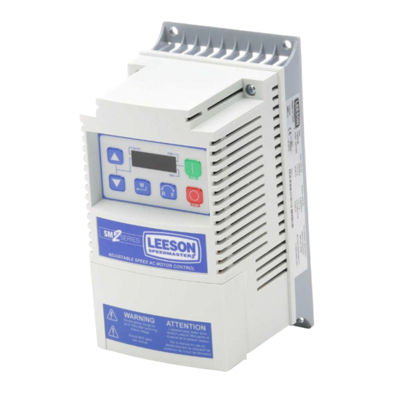
- Page 1 ELECTRIC MOTORS, GEARMOTORS AND DRIVES Flux Vector SPEEDMASTER ADJUSTABLE SPEED AC MOTOR CONTROL Installation and Operation Manual...
-
Page 2: Table Of Contents
Contents Safety information ..............3 Technical data ..............5 Standards and application conditions ............5 Ratings ......................6 Installation ................8 Dimensions and mounting ................8 Electrical installation .................9 3.2.1 Power Connections ...................9 3.2.2 Fuses/cable cross-sections ..............11 3.2.3 Control terminals ..................12 Commissioning ..............13 Local Keypad & Display .................13 Drive Displays and Modes of Operation ..........14 Parameter setting ..................14 Electronic programming module (EPM) ..........14... -
Page 3: About These Instructions
Scope of delivery Important • 1 SM2 Vector inverter After receipt of the delivery, check immediately whether the items LEESON does with EPM installed delivered match the accompanying papers. (see Section 4.4) not accept any liability for deficiencies claimed subsequently. -
Page 4: Safety Information
Safety information General Some parts of LEESON controllers can be electrically live and some surfaces can be hot. Non-authorized removal of the required cover, inappropriate use, and incorrect installation or operation creates the risk of severe injury to personnel or damage to equipment. - Page 5 Safety information All safety information given in these Operating Instructions have the same layout: Signal Word! (characterizes the severity of the danger) Note (describes the danger and informs on how to proceed) Signal Words Icon DANGER! Warns of impending danger. Warning of hazardous electrical Consequences if disregarded:...
-
Page 6: Technical Data
Technical data Technical data Standards and application conditions Conformity Low Voltage Directive (73/23/EEC) Approvals UL 508C Underwriters Laboratories - Power Conversion Equipment Input voltage phase imbalance < 2% Humidity < 95% non-condensing Transport -25 … +70°C Temperature range Storage -20 … +70°C Operation -10 …... -
Page 7: Ratings
Output Current Watts [Hp/kW] Voltage CLim (120V) (240V) Loss 0.33 / 0.25 120 V Single-phase (1/N/PE) 174603 (90 … 132 V) 174604 0.5 / 0.37 240 V Single-phase (2/PE) 174605 1 / 0.75 16.6 (170 … 264 V) 240VAC Models... - Page 8 92% of drive rating or do not exceed 33°C ambient - If P166=3 (10 kHz), derate I to 84% of drive rating or do not exceed 27°C ambient For combinations of the above, please consult LEESON applications support for proper derating.
-
Page 9: Installation
(159) (15) (50) (2.0) 174635 - 174636 Warning! Drives must not be installed where subjected to adverse environmental conditions such as: combustible, oily, or hazardous vapors or dust; excessive moisture; excessive vibration or excessive temperatures. Contact LEESON for more information. -
Page 10: Electrical Installation
• Do not cycle mains power more than once every two minutes. Damage to the drive will result. 3.2.1.1 Mains connection to 120VAC Single-Phase Supply 174603 PE L1 L2 N 174604 174605 3.2.1.2 Mains connection to 240VAC Single-Phase Supply... - Page 11 Installation 3.2.1.3 Mains connection to Three-Phase Supply PE L1 L2 L3 three-phase models (3/PE AC) 3.2.1.4 Motor Connection PES = Protective Earth Shielding Mains and Motor Terminations 12 lb-in (1.3 Nm) 0.25 in (6mm) WARNING! Leakage current may exceed 3.5 mA AC. Minimum size of the protective earth conductor shall comply with local safety regulations for high leakage current equipment.
-
Page 12: Fuses/Cable Cross-Sections
10 A 120V 174604 M16 A C16 A 15 A (1/N/PE) 174605 M25 A C25 A 25 A 174603, 174604, M10 A C10 A 10 A 174605, 174607 240V 174605, 174608 M16 A C16 A 15 A 174609 M20 A... -
Page 13: Control Terminals
Installation 3.2.3 Control terminals Terminal Data for control connections Digital Input: Start/Stop input resistance = 4.3kΩ Analog Common Analog Input: 0...10 VDC input resistance: >50 kΩ Internal DC supply for speed pot +10 VDC, max. 10 mA Analog Input: 4...20 mA input resistance: 250Ω... -
Page 14: Commissioning
Commissioning Commissioning Local Keypad & Display AUTO STOP V0105 START BUTTON: In Local Mode (P100 = 0, 4), this button will start the drive. STOP BUTTON: stops the drive, regardless of which mode the drive is in. WARNING! STOP When JOG is active, the STOP button will not stop the drive! ROTATION: In Local Mode (P100 = 0, 4), this selects the motor rotation direction: - The LED for the present rotation direction (FWD or REV) will be on... -
Page 15: Drive Displays And Modes Of Operation
Commissioning Drive Displays and Modes of Operation Speed Mode Display In the standard mode of operation, the drive frequency output is set directly by the selected reference (keypad, analog reference, etc.). In this mode, the drive display will show the drive’s output frequency. PID Mode Display When the PID mode is enabled and active, the normal run display shows the actual PID setpoint. -
Page 16: Parameter Menu
Commissioning Parameter menu 4.5.1 Basic Setup Parameters Code Possible Settings IMPORTANT Name Default Selection Start Control 0 Local Keypad Use RUN button on front of drive to start P100 Source 1 Terminal Strip Use start/stop circuit wired into the terminal strip. See Section 3.2.3 2 Remote Keypad Only Use RUN button on optional Remote Keypad to start... - Page 17 Commissioning Code Possible Settings IMPORTANT Name Default Selection Minimum {Hz} P103 • P102, P103 are active for all speed P102 Frequency references • When using an analog speed Maximum 60.0 {Hz} p103 reference, also see P160, P161 Frequency Note • P103 cannot be set below Minimum Frequency (P102) •...
- Page 18 Commissioning Code Possible Settings IMPORTANT Name Default Selection Start Method 0 Normal P110 1 Start on Power-up Drive will automatically start when power is applied. 2 Start with DC Brake When start command is applied, drive will apply DC braking according to P174, P175 prior to starting the motor 3 Auto Restart Drive will automatically restart after...
-
Page 19: I/O Setup Parameters
Commissioning 4.5.2 I/O Setup Parameters Code Possible Settings IMPORTANT Name Default Selection Assertion Level P120 and the Assertion Level switch p120 1 Low must both match the desired assertion level unless P100, P121…P123 are all set to 0. Otherwise an F.AL fault 2 High will occur. - Page 20 Commissioning Code Possible Settings IMPORTANT Name Default Selection Note • When input is activated, settings 1...7 override P101 • When TB-13A...TB-13C are configured for Auto References other than MOP, TB-13C overrides TB-13B, and TB-13B overrides TB-13A. Any other Auto Reference will have priority over MOP. •...
- Page 21 Commissioning Code Possible Settings IMPORTANT Name Default Selection Relay Output 0 None Disables the output p140 TB-16, 17 1 Run Energizes when the drive is running 2 Reverse Energizes when reverse rotation is active 3 Fault De-energizes when the drive trips, or power is removed 4 Inverse Fault Energizes when the drive trips...
- Page 22 Commissioning Code Possible Settings IMPORTANT Name Default Selection TB-14 Output 0...23 (same as P140) p142 24 Dynamic Braking For use with Dynamic Braking option 25 Network Activated Requires optional communication module (refer to the network module documentation). Loss of Load P140, P142 = 10: Output will energize p145 Threshold...
-
Page 23: Advanced Setup Parameters
Commissioning 4.5.3 Advanced Setup Parameters Code Possible Settings IMPORTANT Name Default Selection Speed at -999.0 {Hz} 1000 P160 Minimum Signal P161 Speed at 60.0 -999.0 {Hz} 1000 P161 Maximum Signal (4mA) (20mA) P160 V0111 Note • P160 sets the output frequency at 0% analog input •... - Page 24 Commissioning Code Possible Settings IMPORTANT Name Default Selection Slip 10.0 Increase P170 until the motor speed no P170 Compensation longer changes between no load and full load conditions. Current Limit CLim • When the limit is reached, the p171 drive displays , and either the acceleration time increases or the output frequency decreases.
- Page 25 Commissioning Code Possible Settings IMPORTANT Name Default Selection Password 0000 9999 • Must enter password to access P194 parameters • P194 = 0000: Disables password Clear Fault 0 No Action P197 History 1 Clear Fault History Program 0 Operate from User settings p199 Selection 1 Operate from OEM settings...
-
Page 26: Pid Parameters
Commissioning 4.5.4 PID Parameters Code Possible Settings IMPORTANT Name Default Selection PID Mode Disabled • Normal-acting: As feedback P200 increases, motor speed decreases • Reverse-acting: As feedback Normal-acting increases, motor speed increases • PID mode is disabled in Vector Reverse-acting Torque mode (P300 = 5) Note To activate PID mode, one of the TB-13 inputs (P121...P123) must be... - Page 27 Commissioning Code Possible Settings IMPORTANT Name Default Selection Minimum Alarm P204 P205 Use with P140, P142 = 18...23 p214 Maximum Alarm P204 P205 P215 Preset PID P204 P205 TB-13A activated; P121 = 3 and P231 Setpoint #1 P200 = 1 or 2 Preset PID P204 P205...
-
Page 28: Vector Parameters
Commissioning 4.5.5 Vector Parameters Code Possible Settings IMPORTANT Name Default Selection Drive Mode 0 Constant V/Hz Constant torque V/Hz control for P300 general applications 1 Variable V/Hz Variable torque V/Hz control for centrifugal pump and fan applications 2 Enhanced Constant V/Hz For single or multiple motor applications that require better 3 Enhanced Variable V/Hz... - Page 29 Commissioning Code Possible Settings IMPORTANT Name Default Selection Motor Stator 0.00 0.00 {Ω} 64.00 • Will be automatically programmed by P310 Resistance P399 • Changing these settings can Motor Stator {mH} 2000 p311 adversely affect performance. Inductance Contact factory technical support prior to changing Torque Limit When P300 = 5, sets the maximum...
-
Page 30: Network Parameters
Commissioning 4.5.6 Network Parameters Code Possible Settings IMPORTANT Name Default Selection Network Protocol 0 Not Active p400 1 Remote Keypad 2 Modbus RTU This parameter will only display 3 CANopen the selection for the module that is installed. 4 DeviceNet 5 Ethernet 6 Profibus Refer to the Reference Guide specific... - Page 31 Commissioning Code Display Range IMPORTANT (READ ONLY) Name Analog Output {VDC} 10.0 See P150…P155 P525 Actual Output {Hz} 500.0 P527 Frequency Network Speed {Hz} 500.0 Command speed if (Auto: Network) is selected P528 Command as the speed source Terminal and Indicates terminal status using segments of the P530 Protection Status...
-
Page 32: Troubleshooting And Diagnostics
Troubleshooting and Diagnostics Troubleshooting and Diagnostics Status/Warning Messages Status / Warning Cause Remedy DC-injection brake active DC-injection brake activated Deactivate DC-injection brake • activation of digital input • deactivate digital input (P121...P123 = 18) • automatically (P110 = 2, 4...6) •... -
Page 33: Drive Configuration Messages
Troubleshooting and Diagnostics Status / Warning Cause Remedy PID Mode Active Drive has been put into PID Mode. See P200. Sleep Mode is active See P240...P242 Start Pending The drive has tripped into a fault To disable Auto-Restart, set and will automatically restart P110 = 0...2 (P110 = 3...6) PID Mode disabled. -
Page 34: Fault Messages
Troubleshooting and Diagnostics Fault Messages The messages below show how they will appear on the display when the drive trips. When looking at the Fault History (P500), the F. will not appear in the fault message. Fault Cause Remedy High Temperature fault Drive is too hot inside •... - Page 35 Troubleshooting and Diagnostics Fault Cause Remedy Digital Input More than one digital input set for Each setting can only be used once f.1L Configuration fault the same function (except settings 0 and 3) (P121...P123) Only one digital input configured for One input must be set to MOP Up, MOP function (Up, Down) another must be set to MOP Down...
- Page 36 Troubleshooting and Diagnostics Fault Cause Remedy Motor Overload fault Excessive motor load for too long • Verify proper setting of P108 f.PF • Verify drive and motor are proper size for application Flying Restart fault Controller was unable to Check motor / load f.rF synchronize with the motor during restart attempt;...
- Page 37 Notes...
- Page 38 GRAFTON, WISCONSIN 53024-0241 U.S.A. TEL. (262) 377-8810 FAX (262) 377-9025 www.leeson.com A REGAL-BELOIT Company Service Dept. FAX (262) 377-0090 (SV06B)
Need help?
Do you have a question about the 174603 and is the answer not in the manual?
Questions and answers