Table of Contents
Advertisement
Quick Links
CLARITY
Lighting and Media Control
Desktop (MAC/PC)
LSC Lighting Systems (Aust) Pty. Ltd.
ABN 21 090 801 675
65-67 Discovery Road
Dandenong South, Vic.
Australia
Tel: +61 3 9702 8000
email: info@lsclighting.com
web:
www.lsclighting.com
LX-Series & Desktop
OPERATOR MANUAL
Issue 5.3
LX600
Covering software Version 2.4
June 2016
Document number:
Fax:+61 3 9702 8466
LX300
LX900
LX-T01U-A4
Advertisement
Table of Contents

Related Manuals for LSC CLARITY LX300

Summary of Contents for LSC CLARITY LX300
- Page 1 LX300 LX600 LX900 Covering software Version 2.4 June 2016 Document number: LX-T01U-A4 LSC Lighting Systems (Aust) Pty. Ltd. ABN 21 090 801 675 65-67 Discovery Road Dandenong South, Vic. Australia Tel: +61 3 9702 8000 Fax:+61 3 9702 8466 email: info@lsclighting.com web: www.lsclighting.com...
- Page 2 Information contained in this manual is subject to change without notice. In any event, neither LSC Lighting Systems (Aust) Pty. Ltd. nor OpenClear Pty. Ltd. can be held liable for any direct, indirect, special, incidental, or consequential damages or loss whatsoever...
-
Page 3: Table Of Contents
Clarity Contents Operator Manual Contents 3.22.3 VX20 Soft Menus ___________________ 37 1 Latest Features 3.23 External Control Inputs ______________ 38 3.24 VX20 MIDI _______________________ 38 Overview ________________________ 10 3.25 Desklamp Intensity _________________ 39 Version 2.4 _______________________ 10 3.26 Free Mode ________________________ 39 1.2.1 New Fixture Library _________________ 10 1.2.1... - Page 4 Contents Clarity Operator Manual Overview _________________________ 56 10.5 Resizing Panes ____________________ 86 Power Switches ____________________ 56 10.6 Rig Mode Icons ___________________ 86 Grand Master _____________________ 56 10.7 Universal and Direct _______________ 86 Encoder Wheel Touch Screen _________ 56 10.8 Attribute Control Size ______________ 86 8.4.1 Trackpad Mode ____________________ 57 10.9 Preferences ______________________ 88...
- Page 5 Clarity Contents Operator Manual 15.4.2 Timing Tab ______________________ 114 19.7.1 Fixture Specific Presets _____________ 137 15.5 Setting Times ____________________ 115 19.7.2 Fixture Type Presets _______________ 137 19.8 Freesets ________________________ 137 15.5.1 Setting Times by Direct Entry ________ 115 15.6 Fade Curves _____________________ 116 19.8.1 Permutating Freesets _______________ 138 19.8.2...
- Page 6 Contents Clarity Operator Manual 21.8 Programmer Toolbar _______________ 162 Control Booth 21.8.1 Undo / Redo _____________________ 162 25.1 Overview _______________________ 183 21.8.2 None, Prev, All, Next ______________ 163 25.2 Cue-list Playback Settings __________ 184 21.8.3 Grab ___________________________ 163 25.2.1 Cue-list Playback Options ___________ 184 21.8.4 Preview _________________________ 163 25.2.2...
- Page 7 Clarity Contents Operator Manual Show Files & Import/Export 215 Tracking Backup 30.1 Overview _______________________ 215 36.1 Overview ________________________ 245 30.2 Saving and Changing Shows ________ 215 36.2 Setting up Tracking Backup _________ 245 30.2.1 Default FreEsets __________________ 216 36.3 Operating From The Slave __________ 246 30.3 Importing and Exporting Shows _____ 216 30.4 Merging Shows ___________________ 217 Preferences and About...
- Page 8 Contents Clarity Operator Manual 42.10 DMX Universes ___________________ 279 44.1 Introduction _____________________ 286 42.10.1 DMX Slot ________________________ 279 44.2 API (Application Programming Interface) 42.10.2 Attribute. _______________________ 279 Properties ____________________________ 286 42.11 HTP (HIGHEST TAKES PRECEDENCE) __ 279 44.2.1 Buddying/Subgroup properties _______ 286 42.12 LTP (LATEST TAKES PRECEDENCE) ___ 279 44.2.2 Other properties __________________ 286...
-
Page 9: Conventions Used In This Manual
Copyright © 2009 OpenClear Pty. Ltd. All rights reserved. USB and RDM software modules and LX products are developed by LSC Lighting Systems (Aust) Pty. Ltd. www.lsclighting.com Copyright © 2009 LSC Lighting Systems (Aust) Pty. Ltd. All rights reserved. -
Page 10: Latest Features
Latest Features OVERVIEW Both LSC Lighting Systems (Aust) Pty. Ltd. and OpenClear Pty. Ltd. have a corporate policy of continuous improvement covering areas such as product design and documentation. To achieve this goal, we undertake to release software updates for all products on a regular basis. The latest features to be added to this version of Clarity are listed below. -
Page 11: Network Devices
(Clarity product code CT/U). It allows a very large quantity of one type of fixture to be patched to a single unit number. It is most useful when Clarity is being used to control extensive installations of LED strips. Contact LSC for more information. 1.2.7 Minor Changes ... -
Page 12: Introduction/Models
Introduction/Models Clarity Page 12 Operator Manual Introduction/Models OVERVIEW Clarity lighting and media control is available as a Desktop software package for PC or MAC (with optional USB connected peripherals) or in three console models, LX300, LX600 and LX900. There are separate sections in this manual for the Desktop version (with its optional peripherals) and for each of the Console models. -
Page 13: Help
Unique Performance window live interface, a very powerful ad-lib playback matrix grid. HELP The desktop installation includes a copy of this manual that can be found in the LSC folder. The LX consoles contain a copy of this manual that can be viewed on screen and on-board video tutorials of common operations. -
Page 14: Desktop (Pc Or Mac) Clarity
LSC cannot supply a replacement in these circumstances. 3.1.1 Software The Clarity software contained on the Clarity CD is also available as a download from the LSC website, www.lsclighting.com. Both the CD and downloaded versions are identical although both LSC Lighting Systems (Aust) Pty. - Page 15 This takes a few moments and windows will inform you that “Your device is ready to use”. To run Clarity, click on Start\All Programs\LSC\Clarity where you will see all of the installed files. Click on Clarity to run the program.
-
Page 16: Installing Clarity On A Mac
Operator Manual INSTALLING CLARITY ON A MAC When using a Mac type of computer, LSC recommends running Clarity on the OSX 10.10.4 Yosemite operating system. Clarity might not operate correctly with later versions of operating system. We also recommend using a computer with a minimum of an i5 processor. -
Page 17: Vx/Qx Device Driver (Windows & Mac)
Clarity Desktop Clarity Operator Manual Page 17 VX/QX DEVICE DRIVER (WINDOWS & MAC) On early versions of Clarity, some computers had intermittent USB connection problems with VX wings and QX DMX nodes. These issues can cause rapid disconnect/reconnect of USB devices, which can cause an overflow of the operating system’s USB stack. -
Page 18: Demo Mode
DMX512 output is obtained by connecting any of the following devices to the USB port of your computer. Multiple devices can be connected. LSC Clarity QX1 interface provides 1 universe of DMX output. LSC Clarity QX2 interface provides up to 2 universes of DMX output. Page 18... -
Page 19: Desktop Artnet And Sacn Output
Desktop Clarity Operator Manual Page 19 LSC Clarity VX10 wing provides up to 2 universes of DMX output. LSC Clarity VX20 wing provides up to 4 universes of DMX output. Provides 1 universe of DMX output Provides 2 universes of DMX output The QX1 and QX2 interfaces are powered directly from the computer’s USB connector. -
Page 20: Vx20 Programming & Playback Wing
VX20 PROGRAMMING & PLAYBACK WING Programming controls on a computer can be augmented by adding an LSC Clarity VX20 wing. This has all of the features of the VX10 (above) but adds 10 button Playbacks with LCD displays and multiple page selection, Programmer controls (including trackball), MIDI in and out and includes four DMX512 universe outputs. -
Page 21: Starting Clarity
USB port on the PC or in the secure rear port your VX10 or VX20 wing before you start Clarity. To start Clarity, double click on the Clarity icon on your desktop or browse to the LSC menu from your Start button. -
Page 22: Modes Of Operation
Desktop Clarity Clarity Page 22 Operator Manual 3.12 MODES OF OPERATION Clarity's top toolbar is available in all modes of operation and has tabs allowing you to switch between the main windows of: Patch, Rig, Programmer, Palettes, Control Booth, Performance, Levels and Intensity Levels. These windows are un-dockable to suit multi- monitor set-ups or multiple windows. - Page 23 Clarity Desktop Clarity Operator Manual Page 23 LX300 emulation Mode LX600 emulation Mode LX900 emulation Mode The wrapper window’s toolbar provides several options: Fullscreen. The wrapper is set to full screen mode and the wrapper’s toolbar is hidden. Resizable.
-
Page 24: Console Window
Desktop Clarity Clarity Page 24 Operator Manual 3.12.1 Console Window When running in an emulation mode, a top-level Console tab is provided to show the console’s internal encoder wheel touch screen and includes tabs for displaying the virtual control surfaces of the relevant LX console. -
Page 25: Basic Desktop Operation
Clarity Desktop Clarity Operator Manual Page 25 LX600 Playbacks The buttons and faders all work as if they were on the actual console. If you need to press two or more buttons at the same time, pressing and holding a button for half a second will latch that button down. -
Page 26: Patching
Desktop Clarity Clarity Page 26 Operator Manual 3. Control Booth and Performance provide extensive methods of playback. 4. Levels shows you what is happening on the output. All of these operations are described in detail in their relevant sections of this manual. The right end of the top toolbar has buttons for Clear All, Release All and DBO. - Page 27 Clarity Desktop Clarity Operator Manual Page 27 Continue to select fixtures and patch them as above. In the “Connections” Pane, click the down arrow beside the Universe that you have patched your fixtures to and then select the output DMX connector to use. Page 27...
-
Page 28: Programming
Desktop Clarity Clarity Page 28 Operator Manual 3.15 PROGRAMMING Clicking on the Programmer tab reveals the programmer window. Click on Fixtures to select them Selection Sidebar Controls Attribute Controls Fixture type and Group Tabs Tabs Universal Controller Controls All patched fixtures are available in the Selection sidebar, organized in tabs of patched fixture types and groups. -
Page 29: Attribute Quick Menus
Clarity Desktop Clarity Operator Manual Page 29 Attribute Name 3.15.2 Attribute Quick Menus To access the “Attribute Quick Menus, either click on the name of an Attribute Control or right click in the Attribute Control area. Each individual Attribute Control has its own specific quick menu, offering rapid access to common settings relevant to that attribute. -
Page 30: Playback
Desktop Clarity Clarity Page 30 Operator Manual Click Clear to clear all attributes from the Programmer. 3.16 PLAYBACK Desktop Clarity provides several means of playing back the cues that you have recorded. 3.16.1 Control Booth Clicking on the Control Booth tab reveals the Control booth window. Hardware Cue-lists Playbacks Pane. -
Page 31: Adding A Cue-List To A Vx Wing
Clarity Desktop Clarity Operator Manual Page 31 Virtual VX20 Wing VX20 Virtual Wing Display 3.17 ADDING A CUE-LIST TO A VX WING To add a cue-list to a playback on a wing, in the Control Booth window, drag the cue-list from the cue-list column onto the LCD window of the virtual wing playback. -
Page 32: Locking A Playback
Desktop Clarity Clarity Page 32 Operator Manual When you start a new show, only page one exists. When a cue-list is dropped onto any playback on a page of a virtual wing, the next higher page is automatically created. You can manually create any page number (up to 99) by directly selecting that number as described below. -
Page 33: Wing Group Masters
Clarity Desktop Clarity Operator Manual Page 33 Intensity fader: that controls the overall intensity of all fixtures on the output of its playback (Playbacks 1 to 10 only). Flash button: Instantly flashes the intensity of all fixtures on the playback to full level (Playbacks 1 to 10 only). -
Page 34: Extended Wing Controls
Desktop Clarity Clarity Page 34 Operator Manual See above for details on how to display the virtual wing. On the “Create Group Master Dialog” select the required fixture Group to master then choose the Master Type to use: Additive. The fader level is added to the current intensity level of all fixtures in the group. For example, if the fader is at 50% each fixture would get 50% added onto its current level. - Page 35 Clarity Desktop Clarity Operator Manual Page 35 A VX 10 wing has 2 groups of playbacks, 1 to 5 and 6 to 10. A VX 20 wing has 4 groups of playbacks, 1 to 5, 6 to 10, 11 to 15 and 16 to 20. If a cue-list is loaded on a playback and there are un-used (clear) playbacks to the right of the loaded playback in the same group of 5, then the unused playbacks can now be linked to the loaded playback to provide greater live control.
-
Page 36: Programming With The Vx20 Wing
Desktop Clarity Clarity Page 36 Operator Manual “Invert flash button operation on rate faders” changes this operation so that you just move the fader without holding flash to adjust the value, then (if you reach the fader end stop) hold flash to reposition the fader. So the fader is always connected giving you instant control but you can hold the Flash button down to 'scoot' the fader. -
Page 37: Vx20 Soft Menus
Clarity Desktop Clarity Operator Manual Page 37 Fan: When multiple fixtures are selected, holding Fan whilst moving the trackball will fan the values of those attributes. (The same as holding [Ctrl] (PC) or [Cmd] (Mac) when dragging with the mouse in the GUI). ... -
Page 38: External Control Inputs
Desktop Clarity Clarity Page 38 Operator Manual 3.23 EXTERNAL CONTROL INPUTS The “external Inputs” 9-pin D-SUB connector on the back of the VX10 and VX20 wing can be used to connect up to 6 external push buttons that act the same way as the “Go” buttons on the playbacks. -
Page 39: Desklamp Intensity
Clarity Desktop Clarity Operator Manual Page 39 3.25 DESKLAMP INTENSITY The brightness of the LED desk light on the VX wing control can be controlled by holding down [Function] and [Select] together. 3.26 FREE MODE Early versions of Clarity will run in free mode. Clarity will only run in free mode if it was downloaded as version 1.3 or earlier and registered for free mode prior to April 8, 2011. -
Page 40: Lx Consoles
LX Consoles Clarity Page 40 Operator Manual LX Consoles OVERVIEW There are three models in the Clarity LX range of consoles…. LX300 LX600 LX900 Sections 5, 6 and 7 of this manual describe the rear panel connections and the front panel control surfaces of each model respectively. -
Page 41: Lx300 Console
Clarity LX300 Operator Manual Page 41 LX300 Console OVERVIEW LX300 with External Monitor The LX300 has the following features: One 10.4 inch “encoder wheel touch screen”. 15 Fader Playbacks. Each playback has a fader with RGB mode indicator plus Select, Go and Pause/Back buttons. -
Page 42: Power Input And Mains Switch
Note: The LX300 will not start correctly if an external monitor is not plugged in. See section 38 (LX Tools) for details on how to setup the external monitor. Only compatible external touch screens can be used. Contact LSC or your local LSC dealer for compatible touch screen models. -
Page 43: Reset
Circuit to operate button playback 10 5.2.10 Reset The Reset button should only be used if instructed by LSC technical support. The LX300 GUI (Graphical User Interface) can be reset from the LX tools utility. See section 38. Page 43... -
Page 44: Lx300 Front Panel
LX300 Clarity Page 44 Operator Manual LX300 FRONT PANEL The main areas of the LX 300 are: 1. Grand Master and DBO (Dead Black Out) button. 2. 10.4 inch multi function encoder wheel touch screen. 3. Encoder wheels and modifier buttons. 4. - Page 45 Clarity LX300 Operator Manual Page 45 See section 8.7 for details on how to assign cuelists and configure playbacks. 15 Button Playbacks Pause/ Back 30 Playback touch screens Pause/ Back Right Page Left Page Right Page Down Left Page Down 15 Fader Fader Playbacks...
-
Page 46: Lx600 Console
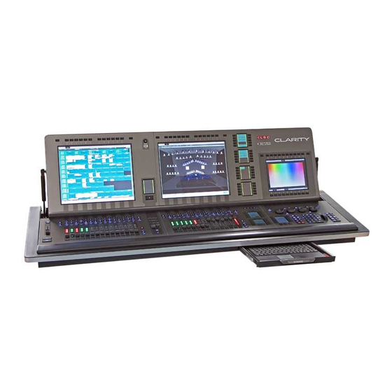
LX600 Clarity Page 46 Operator Manual LX600 Console OVERVIEW LX600 The LX600 has the following features: Pivoting monitor panel. One 10.4 inch “encoder wheel touch screen”. One 17″ touch screen. 15 motorized Fader Playbacks. Each playback has a fader with integral RGB “mode” indicator plus Select, Go, Pause/Back and Flash buttons. -
Page 47: Lx600 Rear Panel
Clarity LX600 Operator Manual Page 47 LX600 REAR PANEL LED Desk lamp LED Desk lamp socket socket External Audio IN Inputs Audio OUT MIDI In, Thru 4 DMX Outputs, & Out A, B, C & D Fuse Mains Switch 4 USB sockets Reset Ethernet 1 2 DVI... -
Page 48: Usb
Circuit to operate button playback 10 6.2.12 Reset The Reset button should only be used if instructed by LSC technical support. The LX600 GUI (Graphical User Interface) can be reset from the LX tools utility. See section 38 Page 48... -
Page 49: Lx600 Front Panel
Clarity LX600 Operator Manual Page 49 LX600 FRONT PANEL The main areas of the LX 600 are: Grand Master and DBO (Dead Black Out) button. 10.4 inch multi function encoder wheel touch screen. Encoder wheels and modifier buttons. ... -
Page 50: Lx900 Console
LX900 Clarity Page 50 Operator Manual LX900 Console OVERVIEW LX900 The LX900 has the following features: Pivoting monitor panel. One 10.4 inch “encoder wheel touch screen”. Two 17″ touch screens. 30 motorized Fader Playbacks in two banks of 15 playbacks. Each playback has a fader with integral RGB mode indicator plus Select, Go and Pause/Back buttons. -
Page 51: Power Input And Mains Switch
Clarity LX900 Operator Manual Page 51 7.2.1 Power Input and Mains Switch A Power Con mains input socket and mains switch connects to the LX300 universal power supply that operates on input voltages between 100 volts and 240 volts, 50-60 Hertz AC. The maximum power consumption is 450 watts. -
Page 52: Led Desk Lamps
Circuit to operate button playback 10 7.2.13 Reset The Reset button should only be used if instructed by LSC technical support. The LX600 GUI (Graphical User Interface) can be reset from the LX tools utility. See section 38 Page 52... -
Page 53: Lx900 Front Panel
Clarity LX900 Operator Manual Page 53 LX900 FRONT PANEL The main areas of the LX 600 are: Grand Master and DBO (Dead Black Out) button. 10.4 inch multi function encoder wheel touch screen. Encoder wheels and modifier buttons. ... -
Page 54: Lx900 Split Cross Fade
LX900 Clarity Page 54 Operator Manual LX900 SPLIT CROSS FADE The LX900 has a “theatre style” split crossfade. It has individual motorised faders for the incoming (up) fade and outgoing (down fade), Go and Pause/back buttons plus a dedicated touch screen for status and configuration. Touch screen Select... -
Page 55: In And Out Faders
Clarity LX900 Operator Manual Page 55 II I (Pause). Pauses any fades in progress. If no fades are in progress, if fades back to the previous step. The indicator in the button lights when the fade to the next cue has completed. The indicator in the button flashes if the cue has been partially overridden. -
Page 56: Lx Console Controls
LX Console Controls Clarity Page 56 Operator Manual LX Console Controls OVERVIEW The following controls on the LX consoles are common to all models. POWER SWITCHES There is a mains power switch located on the rear. There is also a Power switch on the front panel. -
Page 57: Trackpad Mode
Clarity LX Console Controls Operator Manual Page 57 There are also 10 virtual buttons (with labels) across the bottom of the screen that provide different functions for the current mode. These 10 buttons are duplicated by the 10 real buttons directly below them. You can use either the virtual button or the real button to make a selection. -
Page 58: Encoder Wheels And Buttons
LX Console Controls Clarity Page 58 Operator Manual ENCODER WHEELS AND BUTTONS Current functions of Encoder Wheels Encoder Wheels Above the bottom row of virtual buttons on the touch screen are four labels that show the current functions of the four encoder wheels. These functions change as different modes or attribute rows are selected. -
Page 59: Rig
Clarity LX Console Controls Operator Manual Page 59 Fan Centre Hold the button and turn a wheel to fan the attributes being controlled. The centre is fanned symmetrically about the ends. Turn the wheel in the opposite direction to reverse the fan. Double press Fan Centre to latch it on. Press again to un- latch. -
Page 60: Universal
LX Console Controls Clarity Page 60 Operator Manual If you touch on the background area then drag a box, all fixtures within the box are selected. When selecting fixtures, every fixture or group that you select is added to the current selection. This allows you to build up complex selections of fixtures. -
Page 61: Direct
Clarity LX Console Controls Operator Manual Page 61 the left of the screen or pressing one of the 4 buttons on the left of the screen corresponding to that row. The currently selected row is blue. Repeatedly tapping a page selection button (described below) at the bottom of the screen will also step through the rows of its page. -
Page 62: Virtual Wheels
LX Console Controls Clarity Page 62 Operator Manual 8.5.5 Virtual Wheels When either Universal, Direct or Graphical Gobo mode is selected, you can display Virtual Wheels (instead of control widgets) by selecting the V Wheels button at the bottom of the screen. Virtual Wheel V Wheels... -
Page 63: Timing
Clarity LX Console Controls Operator Manual Page 63 The main pages are: Position Colour Gobo The Position page allows you to move the selected fixtures by touching and dragging. Position The Colour page allows you choose a colour for the selected fixture(s) by touching a colour. It has two sub pages;... -
Page 64: Dynamics
LX Console Controls Clarity Page 64 Operator Manual Menu Fade Curves Timing Times can be individually set at the bottom of the screen for the attribute groups of Intensity, Position, Colour and Beam or All times can be selected. Attribute times can be further filtered by touching Choose and then selecting the attributes to be included. -
Page 65: Timeline
Clarity LX Console Controls Operator Manual Page 65 Intensity Fixtures are selected by touching them. Selected fixtures have a yellow border. Touch again to de-select a fixture. If you touch a fixtures number then drag over multiple fixtures, Clarity draws a line showing the drag path and selects each fixture that you drag over. -
Page 66: Keypad And Command Centre
LX Console Controls Clarity Page 66 Operator Manual KEYPAD AND COMMAND CENTRE Command Centre Numeric Keypad Intensity 5 User Wheel buttons Escape Command Centre User Pages Command Buttons Command Buttons 8.6.1 User Buttons The 5 user buttons (U1 to U5) on the right are used to save and recall your favourite screens and attribute selections on the “encoder wheel touch screen”. -
Page 67: Command Centre User Pages
Clarity LX Console Controls Operator Manual Page 67 Undo last programmer action (displays action to be undone, e.g. “Undo clear position”). Append a cue to the last recorded cuelist (displays the name of the cue-list that will be appended to). -
Page 68: Command Buttons
LX Console Controls Clarity Page 68 Operator Manual and then when the button is released, they return to their previous value (via the Undo command). 8.6.6 Command Buttons The 10 command buttons between the touch screen and the keypad are: ... -
Page 69: Playbacks
Clarity LX Console Controls Operator Manual Page 69 other attributes of those fixtures that are at their “Default” level, into the current programmer. In other words, it grabs every attribute of any fixture that currently has any of its attributes active on the output of Clarity. Typing a fixture number(s) and then pressing Grab grabs just that fixture(s) in the programmer and shows the parameter values for the selected fixture(s) on the encoder wheel touch screens “Universal”... -
Page 70: Fader Playbacks
LX Console Controls Clarity Page 70 Operator Manual 8.7.2 Fader Playbacks Select Pause/ Back Right Page Left Page Right Page Down Left Page Down 15 Fader Playbacks Fader Contents Release Indicator Edit Function Main Flash Main Pause/ Back LX600 and LX900 Fader Playbacks The LX600 and LX900 use the lower part of the large touch screen(s) above the playbacks for assigning and configuring the playbacks and to show their contents and status. -
Page 71: Release Button
Clarity LX Console Controls Operator Manual Page 71 8.7.5 Release Button 8.7.5.1 Releasing a Playback To release a playback, tap Release. All buttons of all playbacks flash. Tap any button of the playback to be released. The Release button lights RED when any cue is still active. 8.7.5.2 Releasing a Page of Playbacks Each bank of playbacks has pages split into left and right sides. -
Page 72: Playback Controls
LX Console Controls Clarity Page 72 Operator Manual 8.7.7 Playback Controls (Go): Plays the next cue in the cue-list or restarts a paused fade. Pressing will start the fade to the next cue even if the current fade has not finished. Press Function+ ... -
Page 73: Configuring A Playback
Clarity LX Console Controls Operator Manual Page 73 Clear Cue-lists Playback To assign a Playback, tap the Cue-list name or Chase name (italics) to be assigned. All of the playback touch screens flash red. Tap the playback’s touch screen to which the cue-list or chase is to be assigned. -
Page 74: Locking A Playback
LX Console Controls Clarity Page 74 Operator Manual Pages are changed using either the virtual page buttons on the playback’s touch screen or the real buttons below the playback’s touch screen. The right (page up) and (page down) buttons step through the right pages. ... -
Page 75: Managing Pages
Clarity LX Console Controls Operator Manual Page 75 Locked Playback 8.7.13 Managing Pages Pages can be re-ordered and named. At the bottom of the “Configure Paging” window (above), tap “Re-order/rename pages…” Enter a name for the page Tapping in the “Name” field allows you to enter a name for each page. ... -
Page 76: Page Groups
LX Console Controls Clarity Page 76 Operator Manual It allows you to: Name the bookmark. Give it a number. Tick or un-tick the page groups that you want included in the bookmark. A page group is the left or right side of a VX10 or VX20 wing, or a split page section on an LX console. See below for more details on page groups. -
Page 77: Extended Playback Controls
Clarity LX Console Controls Operator Manual Page 77 8.7.16 Extended Playback Controls If a cue-list is loaded on a playback and there are un-used (clear) playbacks to the right of the loaded playback, then the unused playbacks can be linked to the loaded playback to provide greater live control of Chase Rate, Playback Rate, FX Rate and FX Amplitude. -
Page 78: Clearing A Playback
LX Console Controls Clarity Page 78 Operator Manual Functions for selected column At the top right of the screen choose either “Chase Rate”, Playback Rate, “Effects Rate” or “Effects Amplitude”. The buttons and fader on each of these playbacks (columns), now perform the following functions: ... -
Page 79: Fader Contents Indicator
Clarity LX Console Controls Operator Manual Page 79 Groups Select the required Group then select the “Master Type” drop down box and choose the Master Type: Additive. The fader level is added to the current intensity level of all fixtures in the group. For example, if the fader is at 50% each fixture would get 50% added onto its current level. -
Page 80: Action Buttons
LX Console Controls Clarity Page 80 Operator Manual LX600/LX900 indicators Colour Contents/Function Cue-list Green Chase Yellow “Limiting” Group Master Blue “Additive” Group Master Magenta “Scale +” Group Master White “Inhibitive” Group Master Cyan Extended Playback Control. (Chase or Playback Rate, Effects Rate or Amplitude) ACTION BUTTONS The LX600 and LX900 both have 60 Action Buttons arranged in 6 banks of 10 buttons with 4 pages of memory. -
Page 81: Action Button Pages
Clarity LX Console Controls Operator Manual Page 81 Any Action button can be configured to control either a: Group Preset Freeset Cuelist Page Bookmark Timeline You can put any type of action on any button in any bank, mixing and matching as you please. You can press either the button or the touch screen to “action”... -
Page 82: Release A Cuelist On An Action Button
LX Console Controls Clarity Page 82 Operator Manual When an “Internal” or “Audio” timeline is assigned to an Action button, the physical Action button plays the timeline. If the timeline is playing it stops and rewinds the timeline. When multiple timelines exist, the touch screen Action button select the timeline that is displayed in the Timeline window. - Page 83 Clarity LX Console Controls Operator Manual Page 83 Programmer Tab The right end of the top toolbar on the desktop version has buttons for Clear All, Release All and DBO. Clear All clears all fixtures from all Programmers. Release All releases all fixtures from all Playbacks.
-
Page 84: Basic Operation
Basic Operation Clarity Page 84 Operator Manual Basic Operation OVERVIEW Clarity is a “programmer and playback” lighting controller and uses tracking playback by default. If you are unfamiliar with these terms it is recommended that you read the “Operating Concepts and Terminology” section at the end of this manual before proceeding. The basic steps in controlling lighting fixtures are: ... -
Page 85: Programming
Clarity Basic Operation Operator Manual Page 85 PROGRAMMING Clarity provides many methods of selecting your fixtures. Touching fixtures or groups in Rig mode. See section 12 for details. Clicking on fixtures or groups in the Programmer window Selection sidebar. ... -
Page 86: Customizing Clarity
Customising Clarity Clarity Page 86 Operator Manual 10 Customizing Clarity 10.1 OVERVIEW You can control the look and feel of Clarity to suit your individual requirements. Windows and panes can be un-docked, moved and re-sized and attribute controls can be expanded or compressed as described below. - Page 87 Clarity Customising Clarity Operator Manual Page 87 required but you can also control the size and detail of the Attribute Controls to reduce screen clutter. In the top right corner of the Attribute Control window, are buttons that allow you to control the size of the Attribute Controls for all of the selected fixtures.
-
Page 88: Preferences
Customising Clarity Clarity Page 88 Operator Manual Expanded Display (All selected devices shown) 10.9 PREFERENCES You can customize many of Clarity’s features in the “User Preferences” settings. Click on “Show, Settings, Preferences” then make your selections. User Preferences are described in section 37. 10.10 KEYBOARD SHORTCUTS Keyboard shortcuts allow you to perform certain functions on Clarity by simply pressing a keyboard key or combination of keys. - Page 89 Clarity Customising Clarity Operator Manual Page 89 Select a function from the list and press OK. Now press your new key or combination of keys for the shortcut for this function. To delete a shortcut, select it by clicking on it then click -. See also section 23, “Command Line Programming”.
-
Page 90: Patching Fixtures 11.1 Overview
Patching Fixtures Clarity Page 90 Operator Manual 11 Patching Fixtures 11.1 OVERVIEW Clicking on the Patch window tab reveals the patch window. The Library sidebar lists fixtures by manufacturer and model. If you click on a fixture, additional information for the selected fixture is shown at the bottom of the patch window. The right side shows the 512 patch slots for each internal universe as selected by the Universe # tabs. -
Page 91: Spreadsheet View
Clarity Patching Fixtures Operator Manual Page 91 11.2 SPREADSHEET VIEW Clicking on the Spreadsheet View button displays the patch information in a spreadsheet view. Spreadsheet View The columns can be re-arranged by dragging a column name. The order in a column can be sorted by clicking on the column’s name. -
Page 92: Highlight Channel
Patching Fixtures Clarity Page 92 Operator Manual Quantity: allows you to enter the quantity of fixtures to patch. Location: sets the Universe (A, B etc) and starting DMX slot number. Use custom interval: when ticked, quantities of fixtures greater than 1 will be spaced apart in the patch by the number slots that you enter in the box. -
Page 93: Clone From Other Fixture(S)
Clarity Patching Fixtures Operator Manual Page 93 In the “Library” pane, double click the fixture type to be patched. The “Add Devices” dialog appears for the fixture you have selected and the DMX slot number is automatically assigned so that the intensity channel for that fixture is at the highlighted DMX slot. -
Page 94: Patching Commands
Patching Fixtures Clarity Page 94 Operator Manual entered. Type @ then a DMX slot number and press Enter to make the patch. The patch(s) will be made to the current universe as selected by the tab at the top of the Patch window. Additional patching commands are listed below. -
Page 95: Selecting Fixtures
Clarity Patching Fixtures Operator Manual Page 95 11.7 SELECTING FIXTURES Fixtures are selected in the patch window by clicking on them. Selected fixtures have a black border. Multiple fixtures can be selected. You can select all fixtures of the same type by right clicking on any one of the type and choosing “Select all of this type”... -
Page 96: Intensity Fade Profiles
Patching Fixtures Clarity Page 96 Operator Manual See also section 21.9.11 “Flip”. Flip will alter the current pan and tilt values of the selected moving yoke fixture(s) to the other possible combination of values that achieves the same position on stage. 11.9 INTENSITY FADE PROFILES Intensity Fade Profiles are the relationship or “transfer characteristic”... -
Page 97: Custom Fixtures
Clarity fixture library. If the fixture you are looking for is still not in the library then check to see if it is on the interim list on the LSC website. To request a template navigate to: http://www.lsclighting.com/help-centre/clarity-templates... -
Page 98: Artnet Outputs
Patching Fixtures Clarity Page 98 Operator Manual sACN protocols on the Ethernet ports of LX consoles or the network connector of your computer when running desktop Clarity. Note that universe connections are only presented for internal universes that have one or more devices patched –... -
Page 99: Artnet Unicast
Clarity Patching Fixtures Operator Manual Page 99 Select the required ArtNet Subnet and ArtNet Universe for this output then click OK. Your ArtNet universes are shown in the “Connections” pane….. To see or edit the current ArtNet settings of a universe, click on the drop down box of Universe in question and select ArtNet…... - Page 100 Patching Fixtures Clarity Page 100 Operator Manual ArtNet unicast: The “ArtNet Unicast Routing” dialog opens……. The list at the top are your available “ArtNet Routing Profiles” where <none> is the fixed profile where all universes will be broadcast. Click + to create a new profile. You can create multiple profiles and switch between them selecting a profile and clicking OK.
-
Page 101: Sacn Outputs
Clarity Patching Fixtures Operator Manual Page 101 You can either specify individual ArtNet subnet/universe pairs or ranges. Double-click to edit fields. If you enter a blank for the “Destination IP” it will auto-correct to the broadcast address and a blank for the “Destination Port” will auto-correct to the default ArtNet port. Multiple routes can be added by clicking + and entering the details. -
Page 102: Disable Network Dmx
Patching Fixtures Clarity Page 102 Operator Manual sACN supports a priority setting that is designed for backup solutions. Valid priority settings range from 0 to 200 with higher numbers representing higher priority. The default setting is 100. Data will always be received from the device with the highest priority. For example, you might have two lighting consoles on the network. -
Page 103: Un-Patching Fixtures
Clarity Patching Fixtures Operator Manual Page 103 11.16.4 Un-Patching Fixtures Select the fixture(s) to be un-patched by clicking on them, then right-click and select Unpatch selected. When any fixtures have been un-patched, an “UNPATCHED FIXTURES” pane appears showing those fixtures allowing them to easily be re-patched when required. Un-patched fixtures do not count towards your license limit. -
Page 104: Rig
Clarity Page 104 Operator Manual 12 Rig 12.1 OVERVIEW Rig view is a fixture selection tool and two dimensional visualiser. It shows a geographical view of the patched fixtures (and groups) which you can arrange so that they are positioned as they actually are in your rig. This allows you to rapidly find and select fixtures for programming by clicking on them or touching them or by dragging the mouse cursor through multiple fixtures. -
Page 105: Aligning Fixtures
Clarity Operator Manual Page 105 You can now move and organize the fixtures and groups by dragging and dropping them. Selected items have a yellow border Click a fixture or group then drag it to its new position. Multiple items can be moved by clicking each one the dragging. -
Page 106: Fixture Icons
Clarity Page 106 Operator Manual Note that the fixtures can also be aligned when not in Safe (arrange) mode. 12.4 FIXTURE ICONS Two different styles of icons are available for displaying fixtures: Detailed. Separate areas for Intensity/Colour, Position and Beam are shown. ... -
Page 107: Background Image
Clarity Operator Manual Page 107 Assign Selected Un-assign Selected Assign All Un-assign All The “Contents” pane allows you to select either Fixtures or Groups tabs and then make you selection by clicking on the fixture or group names. You can then assign or un-assign them from the current view by clicking on the arrow buttons. - Page 108 Clarity Page 108 Operator Manual If you click on a fixture then drag over multiple fixtures, Clarity draws a line showing the drag path and selects each fixture that you drag over. If you click on the background area then drag a box, all fixtures within the box are selected. When multiple fixtures are selected, the selection order numbers are shown on the selected icons.
-
Page 109: Universal
Clarity Universal Operator Manual Page 109 13 Universal 13.1 OVERVIEW When you have selected a fixture(s), Universal mode (on the consoles encoder touch screen) provides universal attribute controls that are always in the same locations on the screen and operate in exactly the same way, regardless of which fixture types you have selected. This not only allows multiple types of fixtures to be controlled simultaneously but also simplifies the control of complex fixtures that might use multiple attributes to control an effect or fixtures that use one attribute to change the mode of another attribute. - Page 110 Universal Clarity Page 110 Operator Manual General (One page) Intensity Tilt Iris Shutter Strobe Gobo Wheel 1 Gobo wheel 2 Red/-Cyan Green/-Magenta Blue/-Yellow Colour Wheel 1 Focus Zoom Frost Colour (Two pages) Colour, Page 1 Intensity Cyan Magenta Yellow Green Blue Amber Colour Wheel 1...
- Page 111 Clarity Universal Operator Manual Page 111 Object Directory Object File Effect Effect Parameter Media Server, Keystone Keystone X#1 Keystone Y #1 Keystone X#2 Keystone Y #2 Keystone X#3 Keystone Y #3 Keystone X#4 Keystone Y #4 The following shortcuts are available if you right click on any control on the screen: You can save a shortcut to a page and row allowing you to navigate to it with a single key press.
-
Page 112: Direct
Direct LX300 Operator Manual V1 14 Direct 14.1 OVERVIEW When you have selected a fixture(s), Direct mode provides attribute controls for the selected fixture as specified for that fixture in the fixture library. For example, the fixture being controlled might have a colour wheel with a colour mode attribute and a colour index/spin attribute. -
Page 113: Timing
Clarity Timing Operator Manual Page 113 15 Timing 15.1 OVERVIEW Clarity provides comprehensive controls for the timing of your Cuelists and Cues. Timing information can be entered either when recording a cue, in the Control Booth Window or when editing a cue. Time Presets and Freesets allow you to create building blocks of timing patterns for use in programming or to use them in live playback from the Palettes window. -
Page 114: Cue Attribute Times
Timing Clarity Page 114 Operator Manual Out Delay. If any Intensity values are about to decrease when the cue fades out they will wait for the “Out Delay” time to expire before they start to fade. Increasing intensity values and all other attributes ignore this setting. The default delay time is 0 seconds. ... -
Page 115: Setting Times
Clarity Timing Operator Manual Page 115 attributes by clicking the attributes to be included.You can select them individually or they are multi-selectable with Function + click. Below the filter attributes are the Timing Controls. The detail shown in the Timing Control can be varied by clicking on either: ... -
Page 116: Fade Curves
Timing Clarity Page 116 Operator Manual Right-clicking in the centre column displays a menu where you can choose to: Set fade times. Align delay times that have been skewed and shift fade times accordingly. Equalize unevenly skewed delay times and shift fade times accordingly. ... -
Page 117: Combining Filters
Clarity Timing Operator Manual Page 117 Position filter has been selected. The lower Timing Control still controls IPCB (Intensity, Position, Colour, Beam) but the new Timing Control above it has been filtered for P (Position) information only. No change has yet been made and the new Timing Control is only temporary as indicated by the paler colour and the menu button on the Timing mode changing to “Confirm”... -
Page 118: Complex Timing
Timing Clarity Page 118 Operator Manual 15.7.2 Complex Timing The separate Timing Controls allow you to see a lot of timing information at a glance, even if attribute times are at very different orders of magnitude. The above complex example has the following timing. Intensity (I) is delayed for 0.2 seconds then fades up over 1 second. -
Page 119: Applying Time Presets
Clarity Timing Operator Manual Page 119 The Source pane allows you to filter the timing data that will be recorded by Intensity, Position, Colour and Beam. It also allows you to record the time data of the “Selected fixtures only”. The Options pane allows you to name the Time Preset and to specify the: “Application mode”. -
Page 120: Dynamics (Real Time Effects)
Dynamics Clarity Page 120 Operator Manual 16 Dynamics (real time effects) 16.1 OVERVIEW Dynamics can save you hours of programming time by creating movement from an otherwise static cue. Dynamics mode allows you to add modulation (variation) to any attribute or combination of attributes. -
Page 121: Controlling Dynamics
Clarity Dynamics Operator Manual Page 121 16.3 CONTROLLING DYNAMICS Current waveform Selected Waveform selection Attributes and modifiers Pan Attribute controls Tilt Attribute controls The list at the top-left of the pane shows the attributes that you selected for dynamics to be applied to and at the bottom are the sets of dynamic Attribute Controls, one set per attribute. -
Page 122: Dynamics Attribute Controls
Dynamics Clarity Page 122 Operator Manual 16.3.2 Dynamics Attribute Controls The dynamics Attribute Controls allow you to modify the values that are applied to each individual fixture attribute being modulated by the selected waveform. The values can be directly changed by dragging with the mouse in their respective Attribute Control and they work in the same way as regular Attribute Controls. -
Page 123: Multiple Attribute Dynamics
Clarity Dynamics Operator Manual Page 123 16.4 MULTIPLE ATTRIBUTE DYNAMICS To control another attribute by dynamics click New. The “Add New Effect” dialog box opens and you can select another attribute or multiple attributes as described at the start of this section. When multiple attributes are being controlled by dynamics you can select which attributes to alter by touching them. -
Page 124: Matrix
Matrix Clarity Page 124 Operator Manual 17 Matrix 17.1 OVERVIEW The Programmers Matrix window allows you to place fixtures on a two dimensional grid and then display static or moving imagery on them. Therefore, the fixtures output can be tightly integrated into a complete lighting and visual show. - Page 125 Clarity Matrix Operator Manual Page 125 The available (patched) devices are listed on the left-hand side and are divided into two categories: RGB(AW). All fixtures that use Red Green Blue colour channels including those with Amber or White. Typically these are LED arrays. ...
-
Page 126: Editing A Matrix
Matrix Clarity Page 126 Operator Manual A PixSrc tab is automatically created in the Programmer’s “Selection Sidebar”. It contains the virtual fixtures that are associated with each Pixel Source as described above. 17.5 EDITING A MATRIX To edit or check the settings of an existing matrix click Matrix Settings on the Matrix tab's toolbar. -
Page 127: Transforms
Clarity Matrix Operator Manual Page 127 17.7 TRANSFORMS In the middle of the screen are the transformation controls: Source transform options allow you to isolate sections of the source area, change the source aspect ratio, apply rotation and control moving image playback. Click and drag anywhere within each slider box to vary the setting. -
Page 128: Selecting Media In A Pixel Source
Matrix Clarity Page 128 Operator Manual The media files currently assigned to the Pixel Source (if any) are shown on the left. To add media click Add... then select the file. Clicking on a file in the Current Media pane shows a preview in the Preview pane. ... -
Page 129: Activating A Pixelsource
Clarity Matrix Operator Manual Page 129 17.12 ACTIVATING A PIXELSOURCE Up to this point, all of your media selections and image transforms have been applied to the Pixel Sources (virtual fixtures) and grabbed in the current programmer session. No intensity information (media images) has been grabbed by the current programmer or sent to the output. -
Page 130: Dynamics
Pixel Source). You can add additional wipes as simple monochrome images that you can easily create with any paint program. Contact LSC for details. 17.16 DYNAMICS You can add continuous dynamic effects to any of the transforms by using dynamics tab. Select the Dynamics tab then click New. -
Page 131: Media
Clarity Media Operator Manual Page 131 18 Media 18.1 OVERVIEW Media servers provide video and graphics playback for visual projection on video screens or LED walls. Clarity allows you to control media servers and program them just as if they were another lighting fixture. -
Page 132: Browser
Media Clarity Page 132 Operator Manual Browser Controls Selected Layer Layer Controls Selected Server Level Control Media Server Browser tab 18.5.1 Browser The Browser tab shows the available folders in the left hand pane and the contents (media items) of the selected folder in the right hand pane. At the bottom are the “Layer Control”... -
Page 133: Supported Media Servers
Clarity Media Operator Manual Page 133 timing values that you might set in the Timing tab and dynamics set in the Dynamics tab and are included in a cue by clicking on the red Record button. See section 24, “Record” for details. -
Page 134: Palettes
Palettes Clarity Page 134 Operator Manual 19 Palettes 19.1 OVERVIEW Palettes is the home of groups, presets and freesets that you record and also for Clarity’s in- built library of groups, presets and freesets ready for you to use. (Freesets are a special type of preset described below). -
Page 135: Arranging Palettes And Groups
Clarity Palettes Operator Manual Page 135 Encoder touch screen Palettes with “All” tab selected Clarity automatically creates a group for every different type of fixture that has been patched. These group icons have bevelled corners. Groups that you record have icons with rounded corners. -
Page 136: Groups
Palettes Clarity Page 136 Operator Manual 19.3 GROUPS A group is a selection of fixtures. Groups can be created by selecting the required fixtures in the required order and selecting Record then Group and entering a name. The selection order in the group is used by Clarity when applying effects and freesets. -
Page 137: Presets
Clarity Palettes Operator Manual Page 137 19.7 PRESETS A preset is a special type of memory that can be recorded and recalled. It is stored with specific fixtures numbers or fixture types and usually with only specifically selected attributes (for example, only focus values). -
Page 138: Permutating Freesets
Palettes Clarity Page 138 Operator Manual 19.8.1 Permutating Freesets Freesets “permutate” their values onto the destination fixtures. If the Freeset was recorded using 3 fixtures and it is then applied to 12 fixtures, it will apply the Freeset to the first 3 then apply it again to the next 3, the next 3 and so on. -
Page 139: Freeset Parameter Scripting
Clarity Palettes Operator Manual Page 139 change the attribute masks by clicking on them. When an attribute mask is Green, it is included. A name for the preset can be entered in the name box. Note that Intensity is excluded by default unless you are recording an intensity only preset. Selected Fixtures only. - Page 140 Palettes Clarity Page 140 Operator Manual Many of the Freesets that come with Clarity already have scripts to obtain their desired effects. Right click on some of these Freesets and take a look at the scripts. New Freesets that you have recorded will not have a script but will show a page of script instructions.
-
Page 141: Sample Scripts
Clarity Palettes Operator Manual Page 141 For the same examples as above: 2 fixtures get 0, 0.5; 3 fixtures get 0, 0.25, 0.5; 4 fixtures get 0, 0.166, 0.33, 0.5 etc.). Strict-offset can be used for the Medium Wave and Long Wave freesets. -
Page 142: Palette Icons
Palettes Clarity Page 142 Operator Manual 19.12 PALETTE ICONS 19.12.1 Group Icons Group Icons Each group icon displays its name and a number. The number can be used for keyboard entry of groups. Clarity automatically creates a group for every different type of fixture that has been patched. -
Page 143: Preset And Freeset Shortcuts
Clarity Palettes Operator Manual Page 143 A yellow border indicates that the preset is currently in use. Since freesets are applied using hard values, there is no concept of ‘in use’ for freesets. Hence they only flash their border yellow as they are applied. 19.12.3 Preset and Freeset Shortcuts If you right click on a Preset or Freeset you can choose the following shortcuts... -
Page 144: Removing Presets Or Freesets
Palettes Clarity Page 144 Operator Manual Select the fixtures in the Groups pane and then select the presets or freesets to apply them to the selected fixtures. When fixtures are selected, any applicable presets or freesets turn green to show that they are available. Masking rules apply (see below) to presets or freesets in the Position Presets, Beam Presets and Colour Presets panes. -
Page 145: Build Mode
Clarity Palettes Operator Manual Page 145 19.14.2 Build Mode In the Palettes window, Build mode allows you to select combinations of groups/preset/freesets (with individual live timing as described below) and then trigger them all in one go. On desktop Clarity the Palettes window has a Build button. On LX consoles use the Command button. -
Page 146: Apply Palettes In The Programmer Window146
Palettes Clarity Page 146 Operator Manual By default, the Live Time value will be automatically reset every time that it is used. To retain the Live Time setting for continual use, un-tick the “Auto reset live time” checkbox. By default, the dialog will close once a Preset or Freeset is triggered. You can keep it open by ticking the “Keep open when undocked”... -
Page 147: Masking Dynamic Presets
Clarity Palettes Operator Manual Page 147 19.15.1 Masking Dynamic Presets If a Dynamic Preset or Freeset controls multiple IPCB (Intensity, Position, Colour, Beam) attribute groups, the IPCB filters in the Palettes window allow you to activate only the selected (IPCB) aspect of the effect. -
Page 148: Controlling Dynamics
Palettes Clarity Page 148 Operator Manual 19.16 CONTROLLING DYNAMICS The settings of the dynamics can then be varied by either: Selecting the Dynamics mode on the encoder wheel touch screen and adjusting the controls as described in the Dynamics section. ... -
Page 149: Updating A Preset During Playback
Clarity Palettes Operator Manual Page 149 Drop down To update the preset click Record. 19.20 UPDATING A PRESET DURING PLAYBACK Playback a cue that contains the preset. Press Grab. Attributes that have had a preset applied will display the name of the preset in their respective Attribute Controls as shown on the Encoder touch screen (Universal and Direct) and on the Programmer tab. -
Page 150: Intensities
Intensities Clarity Page 150 Operator Manual 20 Intensities 20.1 OVERVIEW Select the Programmer’s “Intensities” tab by touching More… then Intensities. The screen displays the intensity channel of every patched fixture represented by two separate vertical bars. The left bar shows the programmer level (if any) and the right bar shows the output level. -
Page 151: Channel Controller Mode
Clarity Intensities Operator Manual Page 151 20.2 CHANNEL CONTROLLER MODE “Channel Controller Mode” is a method of lighting control commonly used in television production. Channel controller mode differs from “Programmer Mode” in that when a cue is edited the edits are live and the cue including its edited values remains under the overall level control of its playback master. - Page 152 Intensities Clarity Page 152 Operator Manual keypad entry for speed) and change levels using the intensity wheel. “Intensities” mode gives you an instant picture of the output intensity levels. The cue can still be faded up or down with the playback’s master. Multiple cue-lists can be edited at the same time and the edit sessions will follow the selected playback and the active cue on that playback.
-
Page 153: Programmer
Clarity Programmer Operator Manual Page 153 21 Programmer 21.1 OVERVIEW The Programmer window allows you to: Select Fixtures. Select Groups. Create new Groups. Control fixture attributes. Adjust timing and preview moves. Record cues and presets. ... -
Page 154: Selection Sidebar
Programmer Clarity Page 154 Operator Manual 21.3 SELECTION SIDEBAR All patched fixtures are available in the “Selection Sidebar”. Patched fixtures are automatically organized into tabs of each fixture type and the Groups tab automatically contains a group for every type of patched fixture. You can create your own groups and add them to the groups tab. -
Page 155: Selection Order
Clarity Programmer Operator Manual Page 155 To deselect all selected fixtures in all type tabs click None in the Programmer Toolbar. Keyboard shortcut = [Space-bar] To clear all programmers and deselect all fixtures click Clear All twice. 21.4.4 Selection Order The order in which you select the fixtures is used for certain effects (such as fans and dynamics) and can be also utilized by the sort function described below. -
Page 156: Groups
Programmer Clarity Page 156 Operator Manual 8 Fixtures (devices) are selected. Each Attribute Control controls all 8 fixtures. Pressing Next will refine control to a single fixture within the current selection. Fixture being controlled Yellow arrow shows fixture being controlled 8 fixtures (devices) are selected but control has been refined to a single fixture (StuCl575.1) allowing its attributes to be individually controlled. -
Page 157: Editing Groups
Clarity Programmer Operator Manual Page 157 The order in which the fixtures were selected is saved in the group. This order is used by Clarity when performing effects such as fans and dynamics. The group is automatically assigned a number. The number can be used to select the group. 21.6.1 Editing Groups To edit a group that you have created:... -
Page 158: Subgroups
Programmer Clarity Page 158 Operator Manual groups. The number that you enter in the dialog box determines how many fixtures are in each group. For example, a selection of… 10 fixtures with “Groups of” set to “5” will create 2 groups with 5 fixtures in each group. 20 fixtures with “Groups of”... -
Page 159: Budding
Clarity Programmer Operator Manual Page 159 Next 3,7,11 Next 4,8,12 Next 1,5,9 The Fine button can be used in conjunction with Next or Prev to further refine the selection: Fine+Next Fine+Next Fine+Next Next 2,6,10 21.6.8 Budding Entering a number in Buddying will group the fixture selection into buddies of 2, 3 or 4 etc. For example, a selection of….. -
Page 160: Ctrl Tab
Programmer Clarity Page 160 Operator Manual In this example subgroups is set to 1, so In this example subgroups is set to 2, so when the intensity is fanned, the intensity when the intensity is fanned, the fixtures are fanning is performed across all of the fixture split into 2 subgroups and the fanning is selection. -
Page 161: Position Icons
Clarity Programmer Operator Manual Page 161 In the above example there are a range of colours and fixture1 is at 0% (black), 2 & 3 are at 25%, 4 & 5 are at 50%, 6 & 7 are at 75% and fixture 8 is at 100%. 21.6.12 Position Icons Each fixture has an icon with a white dot showing its current position of its beam at the output. -
Page 162: Blind Programming
Programmer Clarity Page 162 Operator Manual If any attribute of a fixture in any of the unselected fixture type tabs is grabbed in the current programmer a * is displayed on that fixture tab. In the above example, Studio Colours 9 to 16 are not currently selected but they have had some or all of the attributes grabbed (altered) in the current session because they have an * beside their names. -
Page 163: None, Prev, All, Next
Clarity Programmer Operator Manual Page 163 21.8.2 None, Prev, All, Next When more than one fixture is selected, you can refine your control to an individual fixture whilst still maintaining you multiple selection by pressing Prev or Next. Clicking All restores control to all selected fixtures. -
Page 164: Update
Programmer Clarity Page 164 Operator Manual 21.8.8 Update The preferred method of adding new information into an existing cue is to create the new attribute values in the programmer, then “merge” those values into the cue. Update does the merge automatically for you. -
Page 165: Highlight And Lowlight Settings
Clarity Programmer Operator Manual Page 165 The default lowlight setting is an open clear beam at 50% intensity. This provides an easy means of identifying the single fixture that is currently under control. See also “Individual Fixture Control” earlier in this section for more details. Hint: Use the [Home] key to toggle highlight on or off. -
Page 166: Show Undo View
Programmer Clarity Page 166 Operator Manual 21.9.1 Show Undo View Show Undo View shows the entire undo history for the current session. Clicking on a line in the history instantly jumps to that undo level. A separate history is saved for each programmer and each cue-list being edited. -
Page 167: Paste
Clarity Programmer Operator Manual Page 167 21.9.9 Paste Paste pastes the attribute values from the clipboard to the currently selected fixture or multiple fixtures. Hint: There are also Copy and Paste buttons on the front panel command centre. Copy and Paste is a powerful function. -
Page 168: Parking Fixtures
Programmer Clarity Page 168 Operator Manual 21.11 PARKING FIXTURES Fixtures (or just some attributes of fixtures) sometimes need to be isolated from regular programming and playback. For example, you want some work lights that always stay on at low level or a fixture has become faulty and you don’t want it moving and making a noise during a show. -
Page 169: Attribute Quick Menus
Clarity Programmer Operator Manual Page 169 Tilt Attribute Intensity Attribute Control Control In this example, the intensity of 5 fixtures has been dragged to 80%. 21.13.1 Attribute Quick Menus The name of each Attribute Control can be clicked or the Attribute Control itself right-clicked to access the attribute quick menus. -
Page 170: Attribute Control Size
Programmer Clarity Page 170 Operator Manual Fixture quick menu selector Clicked quick menu showing options 21.13.3 Attribute Control Size The Attribute Controls can be re-sized to allow you to trade off between screen area and detail by clicking either: Compact: One line is used for all devices of that type ... -
Page 171: Offset Fanning
Clarity Programmer Operator Manual Page 171 Pressing and holding [Ctrl] (PC) or [Cmd] (Mac) on the keyboard activates the Fanning function and a vertical bar with three nubs appears on each Attribute Control. Fan Bar with 3 nubs Whilst holding [Ctrl] (PC) or [Cmd] (Mac), move the mouse cursor over the top or bottom nub, (it changes to a double headed arrow) then click and drag (whilst holding [Ctrl] or [Cmd]) the nub left or right to fan the values. -
Page 172: Proglets
Proglets is provided in the Appendix of this manual. The LSC Clarity users forum provides a place to share Proglets with other users. It is an Open Source concept where you can create new Proglets and share them with other users to add power and features to Clarity. - Page 173 Clarity Proglets Operator Manual Page 173 To use a Proglet, select the fixtures to be controlled then click on the Proglet. When a Proglet is selected, a box opens with the controls that have been programmed into that Proglet. Here are some examples: To apply the Proglet click Start.
-
Page 174: Command Line Programming
Command Line Programming Clarity Page 174 Operator Manual 23 Command Line Programming 23.1 OVERVIEW You can use command line programming to directly select fixtures, groups, presets and set intensity levels and fade times. If you type in a (fixture unit) number on the keypad, the “command line” automatically appears at the bottom of the encoder wheel touch screen. -
Page 175: Intensity Wheel
Clarity Command Line Programming Operator Manual Page 175 For example, if some fixtures is already selected, to set them all at full intensity press: @ Enter To set them all to 0% press: @ 0 Enter Hint: You can alleviate the need to press Enter when entering 2 digit intensity values by ticking the box for “Auto-enter commandline after 2 digit after AT”... -
Page 176: Groups And Presets
Command Line Programming Clarity Page 176 Operator Manual 23.7 GROUPS AND PRESETS All groups and presets have a number automatically allocated to them. You can use these numbers to select the particular group of preset. On LX consoles press Group or Preset then enter its number on the keypad. ... -
Page 177: Record
Clarity Record Operator Manual Page 177 24 Record 24.1 OVERVIEW The looks that you create with the programmer can be recorded into Cue-lists for later playback. A cue-list can contain any quantity of individual cues. The transition from one cue to the next in the list can be set to be either manually started or automatically started at the completion of the previous cue. -
Page 178: Cue-List Playback Settings And Options
Record Clarity Page 178 Operator Manual Fade out = 2 seconds Prior to pressing Record, you can enter your own names and settings as described below. 24.2.2 Cue-list Playback Settings and Options When recording a New Cue-list, setting “Playback” to either “Tracking” (Default) or “Cue Only”... -
Page 179: Record To Selected Cue-List
Clarity Record Operator Manual Page 179 Record to Existing Cue-list 24.2.5 Record to Selected Cue-list You can record the contents of the Programmer directly to a Cue-list that is on a Playback that you select. Press Record, Select (the “Select” button of the Playback containing the Cue-list) 24.2.6 Contents Options When recording a New Cue-list, setting “Playback”... -
Page 180: Keep Settings
Record Clarity Page 180 Operator Manual with many unwanted channels, all at 0% intensity. This option automatically excludes any fixtures that have their intensity set to 0%. Warning! If a multi parameter fixture has its intensity set to 0% and this option is ticked, none of the parameters for the fixture will be recorded. -
Page 181: Record Output
Clarity Record Operator Manual Page 181 Clearing the programmer after every recording is often used when cues are to be played back in Cue only mode. This is because what you see on stage from the programmer is what will be reproduced when the cue is played back, irrespective of whether you choose to exclude or include unchanged information when you record the cue. -
Page 182: Undo Redo
Record Clarity Page 182 Operator Manual Multiple cue-lists can be in the session control at the same time. Clicking on a cue-list shows the cues in that list and makes it the “current session”. If a cue-list has had any of its cues edited, then the cue-list name turns yellow and so does the name of the individual cue(s) that have been edited. -
Page 183: Control Booth
Clarity Control Booth Operator Manual Page 183 25 Control Booth 25.1 OVERVIEW The Control Booth window is the location of all cue-lists and provides controls to set the playback modes and settings of cue-lists, organise cue-lists in folders and to arrange the order of cue-lists and cues. -
Page 184: Cue-List Playback Settings
Control Booth Clarity Page 184 Operator Manual In the cue-list column the coloured icons shows the LTP (Latest Takes Precedence) status of each cue-list. Cue-list LTP Icons Green. All of the LTP channels in the cue-list are active. Yellow/Green. - Page 185 Clarity Control Booth Operator Manual Page 185 Tracking. (Default setting). When a cue is played back, the attribute values in the cue are applied to the output. Any attribute information from previous cues that has not been updated by the new cue is retained on the output. Therefore, the cue-list will track unchanged information from previous cues to the current cue until overridden by a new value.
- Page 186 Control Booth Clarity Page 186 Operator Manual The Activate and Release settings can both be altered by either entering a value in their respective boxes or by moving their wheel which provides smooth variable control. Playback Rate. Proportionally changes all of the timing information in a cue-list. By default it is set to 100%. The range is 1 to 1000.
-
Page 187: Cue-List Chase Options
Clarity Control Booth Operator Manual Page 187 Action/Go button toggle. When a cue-list is assigned to a Playback or to an LX600 or LX900 “Action” button, if the cuelist is not active, pressing the Playbacks Go button or the LX600 or LX900 Action button will play the cuelist. If the cuelist is active, pressing the button will release the cuelist. -
Page 188: Cue-List Priority Settings
Control Booth Clarity Page 188 Operator Manual If any of the chase options above are selected, the following settings affect the chase. Chase Rate: Sets the chase RATE in Beats Per Minute. Chase Xfade: Sets the transition between steps. When set to 0, the chase snaps from step to step. -
Page 189: Manipulating Cues And Cue-Lists
Clarity Control Booth Operator Manual Page 189 Intensity Fader Manual Fader Reset Rate & Amplitude controls for any FX (dynamics) in the The I (Intensity) fader controls the overall intensity of the fixtures in the cue-list. The Mnl (Manual) fader controls the overall level of all attribute values in the cue-list. It is normally set at full, but can be used to manually fade the entire cue-list in and out. -
Page 190: Cue-List Folders
Control Booth Clarity Page 190 Operator Manual Right-clicking on a cue-list offers the Right-clicking on a cue offers the following following options: options: Rename cue-list Rename Delete cue-list Sync Fx Insert new cue-list Delete cue ... -
Page 191: Copy Full State
Clarity Control Booth Operator Manual Page 191 When unchecked, the copy only contains the hard values in the source cue. The four Radio Buttons are mutually exclusive. Selecting one deselects all others. Exclude redundant state (changes only/tracking). Hard values from the source cue will be copied or merged into the destination cue with the exception that Clarity will exclude any hard values from the source cue that are not required (redundant) because they would exist in the destination cue due to tracking from an earlier cue. -
Page 192: Mark Cues (Move In Black)
Control Booth Clarity Page 192 Operator Manual If “Sync FX” is not active, the dynamic effect will run at its recorded rate. If “Sync FX” is active, the effect will run at a rate that is normalized to a metronome rate of 60BPM (Beats Per Minute). -
Page 193: Change Cue Only
Clarity Control Booth Operator Manual Page 193 Using this fixture selection, Clarity looks at the following cue and copies all the attributes of those fixtures (except intensity) and inserts them into the new Mark cue which is placed between the two cues. When the cue-list is played back and the cue prior to the mark cue finishes its fade, the Mark cue is automatically executed. -
Page 194: Audio Fixture
Control Booth Clarity Page 194 Operator Manual Audio tracks can be added by clicking Add and navigating to the required audio file. Insert your USB stick containing the file and in the file dialog browse to the USB stick (which is found in “Computer”... -
Page 195: Simple Script Language (Macros)
Clarity Control Booth Operator Manual Page 195 The lower section of the “Audio Resources” dialogue box (above) allows you to add “Audio Control Devices” by clicking on the + sign. Select the previously loaded audio file from the drop down box. If you tick the “Use slot number”... -
Page 196: Learn Master Cue-List
Control Booth Clarity Page 196 Operator Manual play Resume the last played/paused audio file. go listname Plays the named cue-list. e.g. go StdColPos jump listname,cuenumber Plays the specified cue number in the named cue-list. e.g. jump StdColPos,2 snapjump listname,cuenumber Snaps to the specified cue number in the named cue-list. goprev listname Plays the previous cue in the named cue-list. -
Page 197: Bookmark
Clarity Control Booth Operator Manual Page 197 Press Finish & Create Cue List to create the new master cue-list. If you selected an audio file then the name of the audio file will be used for the name of the master cue-list. Press Release all then playback the master cue-list that you have just created. -
Page 198: Editing Cues And Cue-Lists
Editing Clarity Page 198 Operator Manual 26 Editing Cues and Cue-lists 26.1 OVERVIEW Playback settings, times and names can be changed in the Control Booth window (Section 25) and in the Playback configuration (Section 8.7.10). The selected settings are automatically saved with the cue-list. -
Page 199: Auto Update
Clarity Editing Operator Manual Page 199 If the “Auto Next” box is ticked, you do not need to press Next as selecting a cue or preset automatically opens the appropriate cue or preset dialog box. On LX consoles you can quickly update the active cue on a playback by pressing Update, Select (the select button of the playback containing the cue to be updated) then Update (or Record). -
Page 200: Editing A Cue
Editing Clarity Page 200 Operator Manual Each cue-list has a Trackback option ticked by default. This means that if this is a tracking cue-list, Clarity will, if necessary, trackback through the cues and update the cue with the hard value that has been tracked through to the current cue. If you deselect Trackback, the updated attribute values will only be applied to the current cue. -
Page 201: Editing Follow Or Wait Times
Clarity Editing Operator Manual Page 201 Brown Yellow/Green Light Grey The attribute is in the The attribute is in the The attribute is cue but has not been cue and has been not included in edited by the edited by the the cue programmer programmer... -
Page 202: Saving The Edit
Editing Clarity Page 202 Operator Manual You can also change the “Follow-on/Halt/Wait” settings for a cue by right clicking on the cue, selecting “Set Follow time” and choosing from Halt, Follow-on or Wait time. If you select “Wait time….” a dialogue box opens allowing you to enter a specific time. Note: If you edit the levels in a cue it can alter the times. -
Page 203: Cue Only" Indication
Clarity Editing Operator Manual Page 203 All of the channels in the cue are listed in the “Device” column and their status as a “cue only” channel is set by ticking their box. The boxes at the top allow you to select either all channels, specific groups of channels (Intensity, Colour, Position or Beam). -
Page 204: Undo Redo Edits
Editing Clarity Page 204 Operator Manual To change a cue into a blocking cue, edit the cue as described above then in the edit session in the programmer window, right-click on the cue and select Block cue. All Block cues in a cue-list can be unblocked. When you unblock a cue-list, Clarity compares each cue to the cue that preceded it and removes any duplicated values. -
Page 205: Performance Window
Clarity Performance Window Operator Manual Page 205 27 Performance Window 27.1 OVERVIEW The performance window provides a unique and intuitive method of playback especially designed for busking, punting or improvising a show. The grid area of the performance window is arranged as a grid of playable items. The top row is fixed and provides column master stop buttons. -
Page 206: Previewing Cue-Lists
Performance Window Clarity Page 206 Operator Manual 27.2 PREVIEWING CUE-LISTS The selected cue-list in the cue-lists browser can be previewed without having to drop it onto a cell by using the preview ► (play) and ■ (stop) controls at the bottom of the browser. Selecting another cue-list automatically stops the previous preview. -
Page 207: Managing The Grid
Clarity Performance Window Operator Manual Page 207 Right clicking on a cue that contains dynamic effects (in the Properties pane above) and selecting Sync FX toggles whether the effects are synchronized to the metronome or not. See section 25.5 for more details on Sync Fx. 27.5 MANAGING THE GRID To manage columns, Right-Click in the top cell of the column and select either: ... - Page 208 Performance Window Clarity Page 208 Operator Manual Source. This allows you to select the source for the cell or to make a deep copy of the current cue-list. A deep copy duplicates the cue-list and sets the new copy as the current source.
-
Page 209: The Metronome
Clarity Performance Window Operator Manual Page 209 The Chase and Playback controls are identical to those in the Control Booth window. See section 25.2.1 “Cue-list Playback Options” in the Control Booth for details. Lock to tempo: When ticked, this causes the cue-list/chase to use the metronome timing as set at the top of the Performance window. -
Page 210: Metronome Settings
Performance Window Clarity Page 210 Operator Manual 27.6.1 Metronome Settings Time sig: Time signature allows you to select the number of beats within a bar, 2/4, 3/4, or 4/4. BPM: (Beats Per Minute) is the tempo of the metronome. Set the tempo by either entering a BPM number or by using the <tap>... -
Page 211: Levels Window
Clarity Levels Window Operator Manual Page 211 28 Levels Window 28.1 OVERVIEW The Levels window provides comprehensive monitoring of levels and activity within Clarity. The selection tabs allow you to view: DMX. Output. Programmer. The levels of all attributes controlled by either programmer. ... -
Page 212: Programmer Values
Intensity Levels Window Clarity Page 212 Operator Manual 28.4 PROGRAMMER VALUES The Programmer tab allows you to view the output of either Programmer or any edit sessions that ere open by clicking on the drop down box or you can tick the Follow current check box to show the contents of the current programmer. -
Page 213: Intensity Levels
Clarity Intensity Levels Window Operator Manual Page 213 29 Intensity Levels 29.1 OVERVIEW The Intensity Levels view complements the normal Levels views by providing intensity specific information with optional auto-compression (hiding levels that are at zero). This makes it much easier to see all of the channels in use when there a large quantity of fixtures. -
Page 214: Console View
Intensity Levels Window Clarity Page 214 Operator Manual Animate Activity changes. If ticked, the channel number will be highlighted in yellow whenever its level is changing. The Detail pane allows you to select the detail that is displayed for each channel number: ... -
Page 215: Show Files & Import/Export
Clarity checks that the legacy library is the latest version available. If it does not find the latest legacy library you will be prompted to download and install the legacy library from the LSC website. Download it to a known location then select Show/Settings/Install legacy fixture file. -
Page 216: Default Freesets
Show Files Clarity Page 216 Operator Manual When a pre-2.4 show is opened and then saved it will be automatically converted to version 2.4 format (with its fixtures embedded in the show file). In addition Clarity automatically creates a “pre-upgrade” copy (without the embedded fixtures) that can be used in any older Clarity systems still running versions earlier than 2.4. -
Page 217: Merging Shows
Clarity Show Files Operator Manual Page 217 Select OK to complete the show export. To import a show select Show/Change show…. The “Change Show” dialogue box opens. Select Open then Import. When you import a show, all the files in the package are copied to their relevant Clarity destinations. -
Page 218: Merge Fixtures
Show Files Clarity Page 218 Operator Manual 30.4.1 Merge Fixtures You can choose to “Ignore”, “Append” or “Merge” Fixtures. Ignore: If you choose “Ignore” then Groups, Cuelists and Playbacks cannot be merged because they need fixture information. Append: Select this option if all of the incoming fixtures are different to the current fixtures. -
Page 219: Merge Groups
Clarity Show Files Operator Manual Page 219 To merge an incoming fixture with the same type of fixture in the current show, select the incoming fixture and the current fixture to which it will be merged. The selected fixtures are removed from the “Incoming fixtures” and “Current fixtures” panes and appear as a single fixture in the “Merge pairs”... -
Page 220: Examples Of Merging
Show Files Clarity Page 220 Operator Manual 30.5 EXAMPLES OF MERGING In very large setups or when programming time is limited is often advantageous to use two consoles when programming and then merge all of the programming for playback on a single console. -
Page 221: Midi
Clarity MIDI Operator Manual Page 221 31 MIDI 31.1 OVERVIEW MIDI (Musical Instrument Digital Interface) is an international standard for data communication between musical instruments, computers and other equipment such as lighting controllers. The MIDI IN connector on LX consoles and VX wings receives signals from a MIDI device such as a keyboard, MIDI sequencer or computer with MIDI output and uses the signals for various functions. -
Page 222: Midi Control Function
MIDI Clarity Page 222 Operator Manual name allows you to select the note that will activate it. The currently assigned note is shown beside each button. See also “Learn MIDI” below. When Clarity receives a MIDI “note on” message that is assigned to a playback function button, it triggers that function on the selected playback. -
Page 223: Midi Timecode
Clarity MIDI Operator Manual Page 223 Set/edit MIDI trigger…. The “MIDI Trigger” dialogue box opens…… Release MIDI Input The “MIDI Input (global)” pane allows you to select the source of the MIDI signal that will control Clarity. Ticking the Go box allows a MIDI note to play the cuelist. To select the MIDI note, click the Learn button (it turns green) and Clarity now listens for the next MIDI message to be sent and automatically assigns it to the “Go”... - Page 224 MIDI Clarity Page 224 Operator Manual Page 224...
-
Page 225: Timecode
Clarity Timecode Operator Manual Page 225 32 Timecode 32.1 OVERVIEW Timecode information can be received by Clarity and used to control the playback of cues at specific times. This allows Clarity’s playback to be perfectly synchronized with other elements of a production that are also locked to the same Timecode. ... -
Page 226: Simulator
Timecode Clarity Page 226 Operator Manual If you right click on the time display you can change the size of the display or show the system clock (with optional tenths of seconds) instead of the Timecode and also make the display persistent over all Clarity windows by selecting “Always on top”. -
Page 227: Timeline
Clarity Timelines Operator Manual Page 227 33 Timeline 33.1 OVERVIEW Timeline allows playback to be synchronised to either timecode, an “internal” timer or to an audio track played back by Clarity. When timecode or the internal timer is running or an audio track is played, Clarity can “Learn”... - Page 228 Timelines Clarity Page 228 Operator Manual On Desktop Clarity the “Timeline” window is on the main menu bar. Timeline To create a new Timeline, in the Timeline window select Timelines. This opens the “Timelines Dialog”. Any existing timelines will be shown. You can select an existing timeline and change its Settings (below) or Delete it.
-
Page 229: Ltc Timelines
Clarity Timelines Operator Manual Page 229 “Audio:” Select an audio track from the drop down box. See section 25.9 for details on how to load audio tracks into Clarity. “Audio pre-roll:” Adds an optional delay on the timeline before the audio track is played. “Capture initial fader level on Go Press”. -
Page 230: Audio Timelines
Timelines Clarity Page 230 Operator Manual When the “Internal” timer is selected as the “Sync:” source (above), the timeline window displays a timeline of the internal timer. Current Time Timeline Position Half Speed Double Speed Play Play The basic operation is: ... -
Page 231: Editing Timelines
Clarity Timelines Operator Manual Page 231 To adjust the audio volume click and drag in the “Vol:” box. You can drag left and right or up and down. The volume value is also “learned” as part of the timeline. See also section 25.11 (Learn) for another method of synchronising playback to audio tracks. 33.6 EDITING TIMELINES The following description uses an “Audio”... -
Page 232: Palettes
Timelines Clarity Page 232 Operator Manual All events in a certain time period can be selected by dragging a box in the timeline. Drag Box All events in a track can be selected by clicking in the track name. in Timeline When Ripple->... -
Page 233: Legacy Ltc Feature
Clarity Timelines Operator Manual Page 233 The physical action buttons perform the same functions as the buttons in the Palettes window above. When multiple timelines exist, the touch screen buttons select the timeline that is displayed in the Timeline window. 33.9 LEGACY LTC FEATURE The “Timeline”... -
Page 234: Automatic Entry Of Events (Learn)
Timelines Clarity Page 234 Operator Manual 33.9.1 Automatic Entry of Events (Learn) If Timecode is being received by Clarity, events can be automatically entered into a Playlist as you play them back in real time. When you play a cue, a new event is automatically created in the selected playlist. -
Page 235: Skip Intervening Events
Clarity Timelines Operator Manual Page 235 When Recede is enabled (default), events will follow the absolute value of the Timecode in both directions of time. If the Timecode jumps back in time, the events will follow. When “Recede” is NOT enabled, events will only follow forward changes in Timecode. For example, if recede is enabled, an event to trigger cue 2 at 0:0:10:0 will trigger cue 2 when the Timecode first becomes later than 0:0:10:0 and will trigger cue 1 when the Timecode first becomes earlier than 0:0:10:0. -
Page 236: Remote Control
If you have Clarity installed on your computer, navigate to your Program Files/LSC/Clarity/Extras folder where you will find the Touchosc templates for the iPad and iPhone/Android. If you do not have Clarity installed on your computer, on your computers web browser, go to….. -
Page 237: Setting Up Osc On Clarity
LX console’s Ethernet connection. Alternately you can connect the console to an existing wireless network. LSC recommends using the “Ethernet 2” port to connect to the wireless router or a network because Clarity’s default setting for Ethernet 2 is “DHCP”. This allows the router or network to automatically assign an IP address to Clarity. -
Page 238: Controlling Clarity With Touch Osc
Remote Control Clarity Page 238 Operator Manual 34.2.3 Controlling Clarity with Touch OSC Run the Touchosc app on your iPhone/iPad/Android. When your iPhone/iPad/Android and Clarity are both correctly configured (described above) and connected to the same wireless network, the five tabs at the top of the screen can be used to select: ... -
Page 239: Controlling Other Devices From Clarity
Clarity Remote Control Operator Manual Page 239 34.2.5 Controlling Other Devices From Clarity To allow Clarity to control OSC devices, open Clarity’s OSC server from the “Show/OSC settings” menu and tick the “Enable OSC client”. OSC messages can be defined in the “Script” fields of cues in the Control Booth. See section 25.10 for information on the script field. - Page 240 Remote Control Clarity Page 240 Operator Manual The “Network Devices” dialog opens…… Devices Messages Pane Pane + button Click the + button on the Devices pane to create a new device and enter the settings for that device. The settings are obtained by running the KissBox editor program on a computer connected to the same network as the KissBox.
- Page 241 Clarity Remote Control Operator Manual Page 241 Using the information from the KissBox editor screen, enter the information in the Clarity “Network Devices” dialog. Press OK to close the dialog and add the new device. In the “Network Devices” dialog, select the device and press + on the Messages pane to open the “Network Message Settings”...
- Page 242 Remote Control Clarity Page 242 Operator Manual The syntax is as follows: ${hex data} Network byte order data. E.g. $a100 will send 2 hex bytes: A1, followed by “string data" The data between the quotes is sent as ASCII text. 8 bit hex data input value.
-
Page 243: Internal Control Values And Value Control Fixtures
Clarity Remote Control Operator Manual Page 243 34.3.1 Internal Control Values and Value control fixtures. In the “Network Devices” dialog, clicking on Value control fixtures… allows you to add special control fixtures to the Clarity show. These are internal fixtures similar to Audio Control Devices or Pixel Source Devices, but they simply control 8 internal variable values. -
Page 244: Scheduler
Remote Control Clarity Page 244 Operator Manual 35 Scheduler 35.1 OVERVIEW Clarity can also be configured to automatically execute various playback actions at specific times and dates with optional repeats for “n” repeats or forever. This function is intended for scenarios where Clarity operates unattended. -
Page 245: Tracking Backup
Clarity Tracking Backup Operator Manual Page 245 36 Tracking Backup 36.1 OVERVIEW Tracking Backup allows another LX console to track a master instance of Clarity on the LX console so that the playback state and show contents are kept in sync on both sessions via a network connection. -
Page 246: Operating From The Slave
Tracking Backup Clarity Page 246 Operator Manual Although the “Tracking Backup Slave” dialog box must remain open on the slave computer, you can still observe the operation of the slave’s windows in the background by clicking on the Patch, Programmer, Palettes, Control Booth, Performance or Levels buttons in the dialog box. -
Page 247: Preferences And About
Clarity Preferences Operator Manual Page 247 37 Preferences and About 37.1 USER PREFERENCES Selecting Show, Settings, Preferences, from the main menu, allows you to customize the operation of Clarity. The default settings for new cue-lists can also be customized or reset to standard. - Page 248 Preferences Clarity Page 248 Operator Manual If ticked, all playbacks will snap to their saved values when Clarity loads. If not ticked they will fade to their values using the fade times recorded in the cues. Only available if “Save/Restore playback” is ticked. See also “DMX holdoff after load” below. ...
- Page 249 These log files can be used by LSC to check the operation of Clarity. Only tick this box if instructed to by LSC. If the box is ticked it has no effect on the operation of Clarity but if the log files are not required they can accumulate over time.
-
Page 250: New Show Preferences
Preferences Clarity Page 250 Operator Manual “Default fade time”. Default = 2000 ms (2 seconds). Set the default fade time that will be used for new parameter values in the programmer when recording a cue. "Blind time". Default = 1000 ms. The fade time that the programmer uses to go in and out of blind mode, entered in ms (milliseconds). -
Page 251: About Clarity
Clarity Preferences Operator Manual Page 251 37.2 ABOUT CLARITY Selecting, Show, About LSC Clarity…, displays the About LSC Clarity dialog box. Version number Here you can find information about your version of the Clarity software. Page 251... -
Page 252: Lx Tools
LX Tools Clarity Page 252 Operator Manual 38 LX Tools 38.1 OVERVIEW LX Tools is a utility program that provides access to hardware configuration, help files and software upgrades on the LX consoles. 38.2 STARTING LX TOOLS To start LX Tools from the console press Function+Fine+Fine at the same time. ... -
Page 253: Software Management
Clarity LX Tools Operator Manual Page 253 38.2.2 Software Management The LX Tools Software Management button provides tools for upgrading the software. See also section 39Error! Reference source not found., “Software Upgrade”. 38.2.3 Help The LX Tools Help button, pprovides a copy of this manual and video tutorials. 38.2.4 Configure Monitors The LX Tools Configure Monitors button allows you to optimise the displays for the physical... -
Page 254: Networking
The LX Tools Networking button allows you to setup the network connection of the two Ethernet ports. See also section 40 for details on how to allow LSC to connect to your console via the internet to resolve problems. Page 254... -
Page 255: Calibrate Touch Screens
The LX Tools Clock button allows you to set the Clock that is displayed beside the Playbacks. 38.2.8 Diagnostics The LX Tools Diagnostics should only be run when instructed by LSC technical support. It requires a password. 38.2.9 System Information The LX Tools System Information button provides system information such as ….. -
Page 256: Software Upgrade
39 Software Upgrade 39.1 OVERVIEW Both LSC Lighting Systems (Aust) Pty. Ltd. and OpenClear Pty. Ltd. have a corporate policy of continuous improvement covering areas such as product design and documentation. To achieve this goal, we undertake to release software updates for all products on a regular basis. -
Page 257: Technical Support
Technical Support Operator Manual 40 Technical Support If you are experiencing problems with Clarity either contact your local LSC agent or post a message on the LSC forum at http://www.lsclighting.com/forums/ LSC technical support staff can remotely interrogate any LX console that is connected to the internet. -
Page 258: Fixture Editor
Clarity fixture library. If the fixture you are looking for is still not in the library then check to see if it is on the interim list on the LSC website. To request a template or check the interim fixture list navigate to: clarity-template.lsclighting.com... -
Page 259: Quick Tour
Clarity Fixture Editor Operator Manual V2.0 Page 259 Slots Fixture Ranges Details Channels Fixture Editor The screen is divided into 4 main panes: Channels… shows the DMX channels and their functions for the fixture. Slots…shows the divisions of the fixture’s wheels (if any) such as gobo, effect or colour. ... - Page 260 Fixture Editor LX300 Page 260 Operator Manual This fixture uses 6 DMX channels to control its functions. From the above chart we can see the DMX levels that determine the settings of each channel. Channel 1. Dimmer/shutter. 0 to 159 dims from 0 to full intensity, 160 to 254 strobes the shutter from slow to fast, 254 to 255 is full open.
- Page 261 Clarity Fixture Editor Operator Manual V2.0 Page 261 Slots Pane Ranges Pane Feature Details Pane Channels Pane The “Channels” pane shows the 6 DMX channels used by this fixture. Clicking on any channel in the “Channels” pane shows the DMX ranges and features for that channel in the “Ranges”...
- Page 262 Fixture Editor LX300 Page 262 Operator Manual Enter a value Adjust value using arrows If you click on a Feature name, the “Fixture Details” pane shows its details and allows you to edit those details. Selected Feature Details of selected Feature Different types of “Features”...
-
Page 263: Writing A New Fixture Template
Clarity Fixture Editor Operator Manual V2.0 Page 263 Click on Colour Wheel Range values for Colour Wheel Once again in the “Ranges” pane you can click on any numeric value to change the value or click on any feature to edit the “Feature Details”. 41.5 WRITING A NEW FIXTURE TEMPLATE To write a new fixture template you will need the DMX channel details for the fixture. - Page 264 Fixture Editor LX300 Page 264 Operator Manual Category Tabs Select the appropriate tab for the “Category” of the first DMX channel of the fixture. The category choices are: Null Intensity Position Colour Beam Content Beam shape ...
- Page 265 Clarity Fixture Editor Operator Manual V2.0 Page 265 There are a large amount of category/group combinations available to choose from, however the vast majority of fixtures use only a small selection of groups as listed below. The most commonly used categories and groups are: Category Most Common Groups Intensity...
-
Page 266: Slots
Fixture Editor LX300 Page 266 Operator Manual Select Group Click on new range If the channel operates as intensity from DMX 0 to 128 and as a shutter from 129 to 255, enter 128 in the upper intensity range. The other ranges automatically adjust. Upper Intensity Repeat the above procedure for all of the channels of your fixture. - Page 267 Clarity Fixture Editor Operator Manual V2.0 Page 267 Tabs Select the appropriate tab for the type of channel you are adding. Each tab has colours or gobos or effects as appropriate, listed under manufacturer and model or range. Select the colour or gobo or effect for this slot then either double click it or click Add.
-
Page 268: Colour Mixing System
Fixture Editor LX300 Page 268 Operator Manual Ensure that the “Use corresponding slots group” box is ticked then click OK. The ranges will be automatically generated based on the slots that you created. If the automatically generated DMX values for the range of each slot are not correct you can manually edit them by clicking in them and entering the correct value or using the increment/decrement arrows that automatically appear when you click on a value. -
Page 269: Conditional Channel
Clarity Fixture Editor Operator Manual V2.0 Page 269 different DMX slot (for example, at the end of the channel assignments) select the fine channel and click “Move Up” or “Move Down” or drag and drop to change the order 41.5.4 Conditional Channel Some fixtures use the values of one DMX channel to determine the functions of another DMX channel. -
Page 270: Virtual Intensity
Fixture Editor LX300 Page 270 Operator Manual The default differentiator number is 1. If you add another channel of the same category then the differentiator is automatically set to 2. A third channel of the same category would be set to 3 etcetera. - Page 271 Clarity Fixture Editor Operator Manual V2.0 Page 271 fixture (using the Fixture editor) and then use that new fixture to compose the new compound fixture. For example, if your new compound fixture has a pan and tilt mechanism and an array of RGB LEDs you will need to create a new fixture that contains only pan and tilt then use this as a module of your new compound fixture.
-
Page 272: Short Name, Save And Export Fixture
Fixture Editor LX300 Page 272 Operator Manual 41.5.9 Short Name, Save and Export Fixture You can give your new fixture a “Short Name”. This name will be used by Clarity in the “Group” tab for this type of fixture. Enter a “Short Name”... -
Page 273: Operating Concepts And Terminology
The operation of Clarity is easily understood when you know the meaning of certain key terms that are frequently used by Clarity. These terms have been adopted by LSC as the best descriptions for functions and operations performed on Clarity and may not be terms adopted on similar equipment. -
Page 274: Playback Control
Operating Concepts & Terminology Clarity Page 274 Operator Manual programmer is used to vary the value of the attribute, the attribute is said to have been touched by the programmer. If the touched value is recorded into a cue-list, then that the attribute is no longer touched. -
Page 275: Advantages Of Tracking
Clarity Operating Concepts & Terminology Operator Manual Page 275 Select fixtures and grab them in a programmer by adjusting their attributes for the desired look. All of these attributes have now been touched. Record the look as a cue in a new cue-list. The first cue in the cue-list will contain the values of all attributes that have been touched by the programmer. -
Page 276: Cue Only Playback
Operating Concepts & Terminology Clarity Page 276 Operator Manual Select dimmer 2 and set to 100%. Record cue 2. Clear programmer, dimmer 2 fades off. Select dimmer 3 and set to 100%. Record cue 3. ... -
Page 277: Content Options
Clarity Operating Concepts & Terminology Operator Manual Page 277 changes that have been made in the programmer since the previous cue in the cue-list was recorded. These cues are suitable for playback in tracking mode. If you intend to playback the cue-list in Cue only mode, then you should include any unchanged information in the cue and not just the changes. -
Page 278: Cue Only (Recording)
Operating Concepts & Terminology Clarity Page 278 Operator Manual Channel 1 Channel 2 Channel 3 Cue 1 Output Cue 2 Output Cue 3 BLOCK Output Cue 4 Output Cue 1 contains hard values for attributes 1, 2 and 3 so when it is played back, the attributes go to 100%, 50% and 25% respectively. -
Page 279: Mark Cues (Move In Black)
Clarity Operating Concepts & Terminology Operator Manual Page 279 42.8.3 Mark Cues (Move in Black) A Mark cue is a special type of cue that you can insert in a cue-list. Mark cues are also known as “move in black” and are used to pre-position fixture attributes without their movements or changes being seen on stage. -
Page 280: Rdm
Operating Concepts & Terminology Clarity Page 280 Operator Manual 42.13 RDM RDM stands for Remote Device Management. It is an “extension” to DMX. Since the inception of DMX it has always been a ‘one way' control system. Data only ever flows in one direction, from the lighting controller outwards to whatever it may be connected to. -
Page 281: Hints And Tips
Clarity Hints and Tips Operator Manual Page 281 43 Hints and Tips 43.1 SIMPLE CUE PLAYBACK If you are a novice and are having trouble understanding tracking the following settings will make Clarity operate in Cue Only mode with the cues automatically playing and releasing when a fader is raised or lowered. -
Page 282: Flashing A Cue
Press Function+ II I to snap to the previous cue. 43.8 OPERATE CLARITY LIKE A MANUAL DESK If you want to work in the same fashion as an LSC maXim console or other similar manual console then you can simply record each of your looks to a separate playback. -
Page 283: Audio Playback
Clarity Hints and Tips Operator Manual Page 283 Gateway 2.0.0.201 Media Server IP Addr: 2.0.0.201 Subnet : 255.0.0.0 Gateway:2.0.0.101 2) Do you have Sun VirtualBox installed on your computer? If so, then by default it re-routes all the network traffic and stops thumbnail exchange from working. In this scenario please disable the VirtualBox Host-Only Ethernet Adapter from within the device manager to resolve the problem. -
Page 284: Recording Only Pan (Or Tilt)
Hints and Tips Clarity Page 284 Operator Manual 3) Do the same for the Red and Green cues. Now you can use the Red, Green and Blue cues to have live colour mixing of the RGB fixtures. 43.14 RECORDING ONLY PAN (OR TILT) When you only adjust Pan, Clarity automatically selects Tilt as well (as usually a position needs both). -
Page 285: Fans Buttons
Clarity Hints and Tips Operator Manual Page 285 and Clarity will look after the color conversion whilst ignoring the Pan/Tilt parameters that don't exist on the par cans. 43.19 FANS BUTTONS The LX consoles provide dedicated Fan End and Fan Centre buttons, located right next to the encoders, to allow quick one handed fanning of any parameter. -
Page 286: Appendix. Proglet Scripting
Appendix Clarity Page 286 Operator Manual 44 Appendix. Proglet Scripting 44.1 INTRODUCTION Clarity’s scripting feature (Proglets) is a very powerful and very advanced feature of Clarity and is thus intended as a power-user feature. The scripts allow the creation of very easy to use Proglet functions with dedicated simple Graphical User Interfaces, but writing proglets is not an easy task. -
Page 287: Feature Ids
Clarity Appendix Operator Manual Page 287 44.2.4 Feature IDs Many other functions instead accept Feature IDs, which are similar to Channel IDs, but are the names you would see on the LX’s universal windows. For example: In many cases these will be the same, but that is not always the case. An example would be for a colour wheel. - Page 288 Appendix Clarity Page 288 Operator Manual setFeatureDynamicValueCentre(featureId, featureValue, bool resetDynamicParams = false) Sets the channel that contains the given feature to be dynamic, and sets the centre value to the given feature value. The optional boolean parameter can be set to TRUE to reset all other dynamic values.
-
Page 289: The Include() Function
Clarity Appendix Operator Manual Page 289 setFeatureDynamicDutyFactor(featureId, valueString) Values should be raw values only (percentage disallowed) setFeatureDynamicAmplitude(featureId, valueString) setFeatureDynamicInvert(featureId, valueString) Values should be 0 or 1 or true or false. No sense in a range but permutations allowed; percentage disallowed. setFeatureDynamicOffset(featureId, valueString, bool strict = false) By default, if you supply a range this will fan the offset values sensibly, so that the last fixture’s offset is not the same as the first fixture’s offset, for example, setFeatureDynamicOffset(“Pan”,... -
Page 290: Modifying And Creating New Proglets
Appendix Clarity Page 290 Operator Manual wheel Normally checkboxes don’t get assigned to encoders, but this can override that. Uses a whole number spin box instead of a decimal number spinbox. Causes the value range to be interpreted along a logarithmic scale. Controls are displayed in the order that they are used in the script. -
Page 291: Object Objects
Clarity Appendix Operator Manual Page 291 Object Function Array String Boolean Number Date RegExp Error EvalError RangeError ReferenceError SyntaxError TypeError URIError Other Properties Math ... -
Page 292: Function Objects
Appendix Clarity Page 292 Operator Manual hasOwnProperty(V) isPrototypeOf(V) propertyIsEnumerable(V) 44.7.3 Function Objects Function Prototype Object Function Properties toString() apply(thisArg, argArray) call(thisArg [, arg1 [, arg2, ...]]) 44.7.4 Array Objects Array Constructor Function Properties isArray(arg) Array Prototype Object Function Properties... -
Page 293: String Objects
Clarity Appendix Operator Manual Page 293 filter(callbackfn [, thisArg]) reduce(callbackfn [, initialValue]) reduceRight(callbackfn [, initialValue]) 44.7.5 String Objects String Constructor Function Properties fromCharCode([char0 [, char1 [,...]]]) String Prototype Object Function Properties toString() valueOf() charAt(pos) ... -
Page 294: Number Objects
Appendix Clarity Page 294 Operator Manual 44.7.7 Number Objects Number Prototype Object Function Properties toString(radix) toLocaleString() toFixed(fractionDigits) toExponential(fractionDigits) toPrecision(precision) 44.7.8 The Math Object Value Properties LN10 LOG2E LOG10E SQRT1_2 ... -
Page 295: Date Objects
Clarity Appendix Operator Manual Page 295 sin(x) sqrt(x) tan(x) 44.7.9 Date Objects Date Constructor Function Properties now() parse(string) UTC(year, month [, date [, hours [, minutes [, seconds [, ms]]]]]) Date Prototype Object Function Properties ... -
Page 296: Regexp Objects
Appendix Clarity Page 296 Operator Manual getUTCMilliseconds() getTimeZoneOffset() setTime(time) setMilliseconds(ms) setUTCMilliseconds(ms) setSeconds(sec [, ms]) setUTCSeconds(sec [, ms]) setMinutes(min [, sec [, ms]]) setUTCMinutes(min [, sec [, ms]]) setHours(hour [, min [, sec [, ms]]]) ... -
Page 297: The Json Object
Clarity Appendix Operator Manual Page 297 44.7.12 The JSON Object Function Properties parse(text [, reviver]) stringify(value [, replacer [, space]]) © 2013 Digia Plc and/or its subsidiaries. Documentation contributions included herein are the copyrights of their respective owners. The documentation provided herein is licensed under the terms of the GNU Free Documentation License version 1.3 as published by the Free Software Foundation. -
Page 298: Index
Index Clarity Page 298 Operator Manual 45 Index <> Button, 59 Compound Fixtures, 59 Action Button Pages, 81 Console Emulation, 24 Action Buttons, 80 Control Booth, 184 Action/Go button toggle, 187 Control Widget Touch Mode, 86 Activate (fade in) time, 186 Copy, 68, 167, 286 Adding a Virtual VX Wing, 30 Copy Full State, 192... - Page 299 Clarity Index Operator Manual Page 299 Encoder Wheel Touch Screen, 56 Include tracked information from Encoder Wheels and Buttons, 58 source cue, 191 Ethernet, 42, 47, 51 Include unchanged information, 181, Exclude redundant state, 181, 192, 279 192, 279 Expanded, 87, 171 Inhibitive Master, 79 Exporting a Cue, 205 Installing Clarity on a Mac, 16...
- Page 300 Index Clarity Page 300 Operator Manual Merging Shows, 218 Programmer Toolbar, 163 Metronome, 210 Programmer Toolbox, 166 MIDI, 38, 222 Programming, 85 Minimum and Maximum Intensity, 96 Quick Menus, 156, 170 Models, 12 Range, 210 Monitors, 255 RDM, 282 Move in Black, 193, 281 Recede, 236 Natural, 171 Record, 164, 178...
- Page 301 Clarity Index Operator Manual Page 301 Time Presets, 118, 286 Trackpad, 57 Timecode, 224 Trigger, 209 Configuration, 226 Trim (knock out remainder), 167 MIDI, 226 Undo, 183, 192, 205 Simulator, 227 Undo / Redo, 163 SMPTE, 226 Undo View, 167 Timecode Configuration Unicast, 99 Old Version, 235...
-
Page 302: Compliance Statements
Connectors with conductive back shells must be used. Federal Communications Commission (FCC) Declaration of Conformity LSC Lighting Systems (Aust) declares that the LX, QX and VX products comply with Part 15 of the FCC Rules. Operation is subject to the following two conditions:...
Need help?
Do you have a question about the CLARITY LX300 and is the answer not in the manual?
Questions and answers