Table of Contents
Advertisement
Advertisement
Table of Contents

Subscribe to Our Youtube Channel
Related Manuals for Leeson SPEEDMASTER SM2 Series

Summary of Contents for Leeson SPEEDMASTER SM2 Series
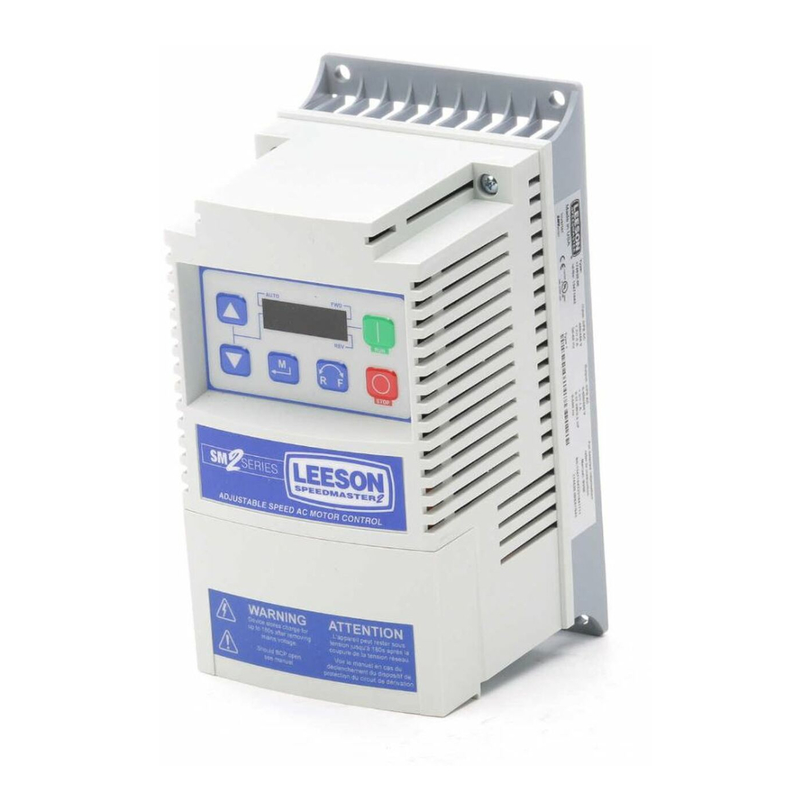
- Page 1 CALL NOW 800-985-6929 http://www.automatedpt.com Email: charles@automatedpt.com ® SPEEDMASTER SM2 Series Flux Vector SM4 Series Flux Vector Installation and Operation Manual A Regal Brand CALL NOW 800-985-6929 http://www.automatedpt.com Email: charles@automatedpt.com...
-
Page 2: Table Of Contents
CALL NOW 800-985-6929 http://www.automatedpt.com Email: charles@automatedpt.com Contents Safety information ...................3 Technical data ..................5 Standards and application conditions ..................5 Ratings ........................... 6 Installation ....................8 Dimensions and mounting ...................... 8 3.1.1 NEMA 1 (IP31) Models ....................8 3.1.3 NEMA 4X (IP65) Models ....................9 Electrical installation ...................... - Page 3 • 1 SM2 or SM4 Vector inverter After receipt of the delivery, check immediately whether the with EPM installed items delivered match the accompanying papers. LEESON does (see Section 4.4) not accept any liability for deficiencies claimed subsequently. • 1 Operating Instructions Claim •...
- Page 4 CALL NOW 800-985-6929 http://www.automatedpt.com Email: charles@automatedpt.com Safety information All safety information given in these Operating Instructions have the same layout: Signal Word! (characterizes the severity of the danger) Note (describes the danger and informs on how to proceed) Signal Words Icon DANGER! Warning of...
-
Page 5: Safety Information
Safety information General DANGER! Some parts of LEESON controllers can be electrically live and some surfaces can be hot. Non-authorized removal of the required cover, inappropriate use, and incorrect installation or operation creates the risk of serious injury to personnel or damage to equipment. -
Page 6: Standards And Application Conditions
CALL NOW 800-985-6929 http://www.automatedpt.com Email: charles@automatedpt.com Technical data Technical data Standards and application conditions Conformity Low Voltage Directive (73/23/EEC) Approvals UL 508C Underwriters Laboratories - Power Conversion Equipment Input voltage phase imbalance < 2% – For central grounded systems, operation is permitted without restrictions. -
Page 7: Technical Data
CALL NOW 800-985-6929 http://www.automatedpt.com Email: charles@automatedpt.com Technical data Ratings 120VAC Doubler / 240VAC Models Mains Output Current Power Type Watts Watt [Hp/kW] Voltage CLim Loss Loss (120V) (240V) 174603 0.33 / 0.25 120 V Single-phase (1/N/PE) 174604- (90 … 132 V) 0.5 / 0.37 174652 174605-... - Page 8 92% of drive rating or do not exceed 33°C ambient - If P166=3 (10 kHz), derate I to 84% of drive rating or do not exceed 27°C ambient For combinations of the above, please consult LEESON applications support for proper derating. CALL NOW 800-985-6929 http://www.automatedpt.com...
-
Page 9: Dimensions And Mounting
.88 (22) WARNING! Drives must not be installed where subjected to adverse environmental conditions such as: combustible, oily, or hazardous vapors or dust; excessive moisture; excessive vibration or excessive temperatures. Contact LEESON for more information. CALL NOW 800-985-6929 http://www.automatedpt.com Email: charles@automatedpt.com... -
Page 10: Installation
(22.2) WARNING! Drives must not be installed where subjected to adverse environmental conditions such as: combustible, oily, or hazardous vapors or dust; excessive moisture; excessive vibration or excessive temperatures. Contact LEESON for more information. CALL NOW 800-985-6929 http://www.automatedpt.com Email: charles@automatedpt.com... -
Page 11: Nema 4X (Ip65) Models
1.06 (27) WARNING! Drives must not be installed where subjected to adverse environmental conditions such as: combustible, oily, or hazardous vapors or dust; excessive moisture; excessive vibration or excessive temperatures. Contact LEESON for more information. CALL NOW 800-985-6929 http://www.automatedpt.com Email: charles@automatedpt.com... -
Page 12: Electrical Installation
CALL NOW 800-985-6929 http://www.automatedpt.com Email: charles@automatedpt.com Installation Electrical installation Installation After a Long Period of Storage STOP! Severe damage to the drive can result if it is operated after a long period of storage or inactivity without reforming the DC bus capacitors. If input power has not been applied to the drive for a period of time exceeding three years (due to storage, etc.), the electrolytic DC bus capacitors within the drive can change internally, resulting in excessive leakage current. -
Page 13: Mains Connection To 240Vac Single-Phase Supply
CALL NOW 800-985-6929 http://www.automatedpt.com Email: charles@automatedpt.com Installation 3.2.1.2 Mains connection to 240VAC Single-Phase Supply 174603 174603 174604 PE L1 L2 N 174604 PE L1 L2 N 174605 174605 174651 174651 174652 174652 174653 174653 174654 174654 174607 174607 174608 PE L1 L2 L3 174608 PE L1 L2 L3 174609... -
Page 14: Installation Recommendations For Emc Compliance
CALL NOW 800-985-6929 http://www.automatedpt.com Email: charles@automatedpt.com Installation 3.2.1.5 Installation Recommendations for EMC Compliance For compliance with EN 61800-3 or other EMC standards, motor cables, line cables and control or communications cables must be shielded with each shield/screen clamped to the drive chassis. This clamp is typically located at the conduit mounting plate. -
Page 15: Dynamic Brake Connections
CALL NOW 800-985-6929 http://www.automatedpt.com Email: charles@automatedpt.com Installation 3.2.1.7 Dynamic Brake Connections For NEMA 1 and NEMA 4X Drives rated up to 25 HP the Dynamic Brake connections are made as illustrated herein. Refer to the SM2 and SM4 Dynamic Brake instructions for complete information. NEMA 1 (IP31) up to 30 HP NEMA 4 (IP65) up to 10 HP The 40...40HP (30...45kW) models include a dynamic brake transitor as standard and only require the connection... -
Page 16: Fuses/Cable Cross-Sections
CALL NOW 800-985-6929 http://www.automatedpt.com Email: charles@automatedpt.com Installation 3.2.2 Fuses/cable cross-sections Note Observe local regulations. Local codes may supersede these recommendations Recommendations Miniature Fuse Input Power Wiring Type Fuse circuit Breaker (L1, L2, L3, PE) breaker (N. America) [mm²] [AWG] 174603 M10 A C10 A 10 A... -
Page 17: Control Terminals
CALL NOW 800-985-6929 http://www.automatedpt.com Email: charles@automatedpt.com Installation Observe the following when using Ground Fault Circuit Interrupters (GFCIs): • Installation of GFCI only between supplying mains and controller. • The GFCI can be activated by: - capacitive leakage currents between the cable screens during operation (especially with long, screened motor cables) - connecting several controllers to the mains at the same time - RFI filters... -
Page 18: Commissioning
CALL NOW 800-985-6929 http://www.automatedpt.com Email: charles@automatedpt.com Commissioning Control Terminal Strip for 15HP (11 kW) and Greater Drives: ALsw ALsw ALsw 4.5 lb-in 6 25 4 11 13A 13B 13C 14 30 2 13A 13B 13C 13A 13B 13C (0.5 Nm) +15V 0.25 in (6 mm) 2k …... - Page 19 CALL NOW 800-985-6929 http://www.automatedpt.com Email: charles@automatedpt.com Commissioning Display START BUTTON In Local Mode (P100 = 0, 4, 6), this button will start the drive. STOP BUTTON Stops the drive, regardless of which mode the drive is in. WARNING! STOP When JOG is active, the STOP button will not stop the drive! ROTATION In Local Mode (P100 = 0, 4, 6), this selects the motor rotation direction:...
- Page 20 CALL NOW 800-985-6929 http://www.automatedpt.com Email: charles@automatedpt.com Commissioning NOTE If the keypad is selected as the auto reference (P121…P124 is 6) and the corresponding TB-13 input is closed, the AUTO LED and s t LEDs will both be on. FUNCTIONS THAT FOLLOW ARE APPLICABLE TO SM2 DRIVES 15HP (11kW) AND GREATER CTRL CTRL The CTRL pushbutton selects the start and speed reference control sources for the drive.
-
Page 21: Drive Displays And Modes Of Operation
CALL NOW 800-985-6929 http://www.automatedpt.com Email: charles@automatedpt.com Commissioning Display START CONTROL The REMOTE/LOCAL LEDs indicate the current start control source. If the start control source is a remote keypad or the network, then both LEDs will be OFF. REFERENCE CONTROL The AUTO/MANUAL LEDs indicate the current reference control source. IF P113 = 0 or 2, the AUTO/MANUAL LEDs will match the AUTO LED on the 4-character display. -
Page 22: Parameter Setting
CALL NOW 800-985-6929 http://www.automatedpt.com Email: charles@automatedpt.com Commissioning Parameter setting Status/fault messages Change Parameters StoP P194 = 0000 p100 60.0 PASS 20.0 p104 15 s 0225 12.0 p541 F.AF 60 s F.UF V0106 Electronic programming module (EPM) The EPM contains the drive’s operational memory. Parameter settings are stored in the EPM and setting changes are made to the “User settings”... -
Page 23: Parameter Menu
CALL NOW 800-985-6929 http://www.automatedpt.com Email: charles@automatedpt.com Commissioning Parameter menu 4.5.1 Basic Setup Parameters Code Possible Settings IMPORTANT Name Default Selection Start Control 0 Local Keypad Use RUN button on front of drive to P100 Source start 1 Terminal Strip Use start/stop circuit wired into the terminal strip. - Page 24 CALL NOW 800-985-6929 http://www.automatedpt.com Email: charles@automatedpt.com Commissioning Code Possible Settings IMPORTANT Name Default Selection Standard 0 Keypad (Local or Remote) Selects the default speed or torque P101 Reference reference when no Auto Reference is 1 0-10 VDC Source selected using the TB-13 inputs 2 4-20 mA 3 Preset #1 4 Preset #2...
- Page 25 CALL NOW 800-985-6929 http://www.automatedpt.com Email: charles@automatedpt.com Commissioning Code Possible Settings IMPORTANT Name Default Selection Motor Overload motor current rating P108 P108 = x 100 SM2 output rating Example: motor = 3 amps; SM2 = 4 amps; P108 = 75% Note Do not set above the rated motor current as listed on the motor dataplate.
- Page 26 CALL NOW 800-985-6929 http://www.automatedpt.com Email: charles@automatedpt.com Commissioning Code Possible Settings IMPORTANT Name Default Selection Note • P110 = 0, 2: Start command must be applied at least 2 seconds after power-up; fault will occur if start command is applied too F.UF soon.
-
Page 27: I/O Setup Parameters
CALL NOW 800-985-6929 http://www.automatedpt.com Email: charles@automatedpt.com Commissioning 4.5.2 I/O Setup Parameters Code Possible Settings IMPORTANT Name Default Selection Auto/Manual The reference is dictated by the 0 Terminal Strip Control P113 Control settings and state of the TB-13x terminals. If no AUTO reference has been setup on the terminal strip then reference control is dictated by P101. - Page 28 CALL NOW 800-985-6929 http://www.automatedpt.com Email: charles@automatedpt.com Commissioning Code Possible Settings IMPORTANT Name Default Selection TB-13A Input 0 None Disables input P121 Function 1 AUTO Reference: 0-10 VDC For frequency mode, see P160...P161, For PID mode, see P204…P205, TB-13B Input 2 AUTO Reference: 4-20 mA For vector torque mode, see P330 P122 Function...
- Page 29 CALL NOW 800-985-6929 http://www.automatedpt.com Email: charles@automatedpt.com Commissioning Code Possible Settings IMPORTANT Name Default Selection WARNING! If the input defined to “Start Sequence” is opened during a sequence, the drive will exit sequencer mode and will run at the specified standard or alternate speed source (dependent on drive configuration).
- Page 30 CALL NOW 800-985-6929 http://www.automatedpt.com Email: charles@automatedpt.com Commissioning Code Possible Settings IMPORTANT Name Default Selection Preset Speed #1 {Hz} P131 PRESET 13A 13B 13C 13D SPEED Preset Speed #2 {Hz} P132 Preset Speed #3 {Hz} P133 Preset Speed #4 {Hz} P134 4 (alternate) Preset Speed #5 {Hz}...
- Page 31 CALL NOW 800-985-6929 http://www.automatedpt.com Email: charles@automatedpt.com Commissioning Code Possible Settings IMPORTANT Name Default Selection Relay Output 11 Local Keypad Control Active P140 (cont) TB-16, 17 12 Terminal Strip Control Active Energizes when the selected source is active for start control 13 Remote Keypad Control Active 14 Network Control Active 15 Standard Reference Active...
- Page 32 CALL NOW 800-985-6929 http://www.automatedpt.com Email: charles@automatedpt.com Commissioning Code Possible Settings IMPORTANT Name Default Selection Digital Output Used to invert the selections for P144 Invert Invert Inversion P140 (Relay Output) and P142 (TB-14 P144 P142 P140 Output). EXAMPLE: When P140 = 6 (AT SPEED), the relay is energized when output frequency = commanded frequency.
- Page 33 CALL NOW 800-985-6929 http://www.automatedpt.com Email: charles@automatedpt.com Commissioning Code Possible Settings IMPORTANT Name Default Selection TB-30 Scaling: 1000 If P150 = 5 or 6, sets the Torque (as P154 Torque a percent of motor rated torque) at which output equals 10 VDC TB-30 Scaling: {kW} 200.0...
-
Page 34: Advanced Setup Parameters
CALL NOW 800-985-6929 http://www.automatedpt.com Email: charles@automatedpt.com Commissioning 4.5.3 Advanced Setup Parameters Code Possible Settings IMPORTANT Name Default Selection Speed at -999.0 {Hz} 1000 P160 Minimum Signal P161 Speed at 60.0 -999.0 {Hz} 1000 P161 Maximum Signal (4mA) (20mA) P160 V0111 Note •... - Page 35 CALL NOW 800-985-6929 http://www.automatedpt.com Email: charles@automatedpt.com Commissioning Code Possible Settings IMPORTANT Name Default Selection Base Frequency 60.0 10.0 {Hz} 1500 P167 Fixed Boost 30.0 P168 V0112 Note • P167 = rated motor frequency for standard applications • P168 default setting depends on drive rating Accel Boost 20.0 Accel Boost is only active during...
- Page 36 CALL NOW 800-985-6929 http://www.automatedpt.com Email: charles@automatedpt.com Commissioning Code Possible Settings IMPORTANT Name Default Selection DC Brake Time 999.9 P175 Note CONFIRM MOTOR SUITABILITY FOR USE WITH DC BRAKING DC Brake voltage (P174) is applied for the time specified by P175 with the following exceptions: •...
- Page 37 CALL NOW 800-985-6929 http://www.automatedpt.com Email: charles@automatedpt.com Commissioning Code Possible Settings IMPORTANT Name Default Selection Skip frequency 1 {Hz} • Drive will not run in the defined skip P181 range; used to skip over frequencies Skip frequency 2 {Hz} P182 that cause mechanical vibration •...
- Page 38 CALL NOW 800-985-6929 http://www.automatedpt.com Email: charles@automatedpt.com Commissioning Code Possible Settings IMPORTANT Name Default Selection Clear Fault 0 No Action P197 History 1 Clear Fault History Program 0 Operate from User settings P199 Selection 1 Operate from OEM settings See Notes 1, 2 and 3 2 Reset to OEM default See Note 1 settings...
-
Page 39: Pid Parameters
CALL NOW 800-985-6929 http://www.automatedpt.com Email: charles@automatedpt.com Commissioning 4.5.4 PID Parameters Code Possible Settings IMPORTANT Name Default Selection PID Mode Disabled • Normal-acting: As feedback P200 increases, motor speed decreases • Reverse-acting: As feedback Normal-acting increases, motor speed increases • PID mode is disabled in Vector Reverse-acting Torque mode (P300 = 5) •... - Page 40 CALL NOW 800-985-6929 http://www.automatedpt.com Email: charles@automatedpt.com Commissioning Code Possible Settings IMPORTANT Name Default Selection Proportional 100.0 Used to tune the PID loop: P207 Gain • Increase P207 until system becomes unstable, then decrease Integral Gain 20.0 P208 P207 by 10-15% •...
- Page 41 CALL NOW 800-985-6929 http://www.automatedpt.com Email: charles@automatedpt.com Commissioning Code Possible Settings IMPORTANT Name Default Selection Sleep Entry 0 Enter SLEEP if Drive Speed For time longer than P241 P244 Mode <P240 1 Enter SLEEP if Feedback For time longer than P241 or same >P243 as Sel 0 2 Enter SLEEP if Feedback...
-
Page 42: Vector Parameters
CALL NOW 800-985-6929 http://www.automatedpt.com Email: charles@automatedpt.com Commissioning 4.5.5 Vector Parameters Code Possible Settings IMPORTANT Name Default Selection Drive Mode 0 Constant V/Hz Constant torque V/Hz control for P300 general applications 1 Variable V/Hz Variable torque V/Hz control for centrifugal pump and fan applications 2 Enhanced Constant V/Hz For single or multiple motor applications that require better... - Page 43 CALL NOW 800-985-6929 http://www.automatedpt.com Email: charles@automatedpt.com Commissioning Code Possible Settings IMPORTANT Name Default Selection Motor Stator 0.00 0.00 {Ω} 64.00 • Will be automatically P310 Resistance programmed by P399 • Changing these settings can Motor Stator {mH} 2000 P311 adversely affect performance. Inductance Contact factory technical support prior to changing...
- Page 44 CALL NOW 800-985-6929 http://www.automatedpt.com Email: charles@automatedpt.com Commissioning Code Possible Settings IMPORTANT Name Default Selection Motor Auto- 0 Calibration Not Done • If P300 = 4 or 5, motor calibration P399 calibration must be performed if P399 is not set to 3 (bypass calibration). 1 Standard Calibration Enabled •...
-
Page 45: Network Parameters
CALL NOW 800-985-6929 http://www.automatedpt.com Email: charles@automatedpt.com Commissioning 4.5.6 Network Parameters Code Possible Settings IMPORTANT Name Default Selection Network 0 Not Active This parameter will only display P400 Protocol the selection for the module that is 1 Remote Keypad installed. 2 Modbus RTU 3 CANopen 4 DeviceNet 5 Ethernet... -
Page 46: Diagnostic Parameters
CALL NOW 800-985-6929 http://www.automatedpt.com Email: charles@automatedpt.com Commissioning Code Possible Settings IMPORTANT Name Default Selection Current Network 0 No Fault P405 Fault 1 F.nF1 Netldle Mode 2 F.nF2 Loss of Ethernet I/O connection 3 F.nF3 Network Fault 4 F.nF4 Explicit Message Timeout 5 F.nF5 Overall Network Timeout 6 F.nF6... - Page 47 CALL NOW 800-985-6929 http://www.automatedpt.com Email: charles@automatedpt.com Commissioning Code Display Range IMPORTANT (READ ONLY) Name Heatsink Temp {°C} Heatsink temperature P512 0-10 VDC Input {VDC} 10.0 Actual value of signal at TB-5 P520 4-20 mA Input {mA} 20.0 Actual value of signal at TB-25 P521 TB-5 Feedback P204...
-
Page 48: Terminal & Protection Status Display
CALL NOW 800-985-6929 http://www.automatedpt.com Email: charles@automatedpt.com Commissioning Code Display Range IMPORTANT (READ ONLY) Name Sequencer: Time {P708} 6553.5 Unit depends on P708 (0.1sec, sec or minutes) P562 Remaining in {P708} 65535 Active Segment Sequencer: 65535 P563 Number of cycles since start Sequencer: 65535... -
Page 49: Onboard Communications Parameters 15-25 Hp
CALL NOW 800-985-6929 http://www.automatedpt.com Email: charles@automatedpt.com Commissioning 4.5.8 Onboard Communications Parameters 15-30HP (11-22kW) The P6xx Onboard Communication parameters are applicable to the 15HP (11kW) and greater models only. Code Possible Settings IMPORTANT Name Default Selection P600 Network Enable 0 Disabled This parameter enables the onboard network communications. -
Page 50: Sequencer Parameters
CALL NOW 800-985-6929 http://www.automatedpt.com Email: charles@automatedpt.com Commissioning Code Possible Settings IMPORTANT Name Default Selection 0 No action Modbus Network Timeout P626 Action 1 Stop (P111) 2 Quick Stop 3 Controller Inhibit 4 Trip Fault, F.nF1 0 No action Lecom 1 Controller Inhibit 2 Quick Stop 3 Trip Fault, F.nF1 Network Messages... - Page 51 CALL NOW 800-985-6929 http://www.automatedpt.com Email: charles@automatedpt.com Commissioning Code Possible Settings IMPORTANT Name Default Selection Sequencer: 0 Restart at beginning of Pointed by TB13x P706 Action after sequence Stop/Start 1 Restart at beginning of current transition or Fault Restart 2 Start at beginning of prior segment 3 Start at beginning of next segment...
- Page 52 CALL NOW 800-985-6929 http://www.automatedpt.com Email: charles@automatedpt.com Commissioning Code Possible Settings IMPORTANT Name Default Selection Segment #2 Bit0 Relay bit = 0: OFF (De-energized) P718 Digital Output bit = 1: ON (Energized) Bit1 TB14 State The corresponding digital output/ relay must be set to accept value the from the sequencer: P140, P142=27 Segment #2 0.00...
- Page 53 CALL NOW 800-985-6929 http://www.automatedpt.com Email: charles@automatedpt.com Commissioning Code Possible Settings IMPORTANT Name Default Selection Segment #5 Segment #5 -500.0 {Hz} 500.0 If P112 = 1, negative sign forces P730 Frequency reverse direction Setpoint Segment #5 {sec} 3600.0 20.0 P731 Accel/Decel Time Segment #5 {P708} 6553.5...
- Page 54 CALL NOW 800-985-6929 http://www.automatedpt.com Email: charles@automatedpt.com Commissioning Code Possible Settings IMPORTANT Name Default Selection Segment #7 Bit0 Relay bit = 0: OFF (De-energized) P743 Digital Output bit = 1: ON (Energized) Bit1 TB14 State The corresponding digital output/ relay must be set to accept value the Segment #7 0.00 {VDC}...
- Page 55 CALL NOW 800-985-6929 http://www.automatedpt.com Email: charles@automatedpt.com Commissioning Code Possible Settings IMPORTANT Name Default Selection Segment #10 Segment #10 -500.0 {Hz} 500.0 If P112 = 1, negative sign forces P755 Frequency reverse direction Setpoint Segment #10 {sec} 3600.0 20.0 P756 Accel/Decel Time Segment #10 {P708} 6553.5...
- Page 56 CALL NOW 800-985-6929 http://www.automatedpt.com Email: charles@automatedpt.com Commissioning Code Possible Settings IMPORTANT Name Default Selection Segment #12 Bit0 Relay bit = 0: OFF (De-energized) P768 Digital Output bit = 1: ON (Energized) Bit1 TB14 State The corresponding digital output/ relay must be set to accept value the from the sequencer: P140, P142=27 Segment #12 0.00...
- Page 57 CALL NOW 800-985-6929 http://www.automatedpt.com Email: charles@automatedpt.com Commissioning Code Possible Settings IMPORTANT Name Default Selection Segment #15 Segment #15 -500.0 {Hz} 500.0 If P112 = 1, negative sign forces P780 Frequency reverse direction Setpoint Segment #15 {sec} 3600.0 20.0 P781 Accel/Decel Time Segment #15 {P708} 6553.5...
- Page 58 CALL NOW 800-985-6929 http://www.automatedpt.com Email: charles@automatedpt.com Commissioning Code Possible Settings IMPORTANT Name Default Selection End Segment: Bit0 Relay bit = 0: OFF (De-energized) P793 Digital Output bit = 1: ON (Energized) Bit1 TB14 State The corresponding digital output/ relay must be set to accept value the from the sequencer: P140, P142=27 End Segment: 0.00...
-
Page 59: Sequencer Flow Diagram Left
CALL NOW 800-985-6929 http://www.automatedpt.com Email: charles@automatedpt.com Commissioning 4.5.9.1 Sequencer Parameters Sequencer Flow Diagram “Start Segment” number selection Digital Input priority: TB-13A - Lowest TB-13B TB-13C Start TB-13D - Highest Drive Stop/Start Control Segment P121 P122 P123 P124 P701 Start from Local Keypad P100 P700... - Page 60 CALL NOW 800-985-6929 http://www.automatedpt.com Email: charles@automatedpt.com Commissioning 4.5.9.2 Sequencer Parameters Action after Stop/Start (P100) transition/digital input (if setup for sequencer mode) transition or restart after trip. P706 Action Restart at beginning of sequence (pointed by TB13x) Restart at beginning of current segment Start at beginning of prior segment Start at beginning of next segment P710...
-
Page 61: 4.5.9.3 Sequencer Status
CALL NOW 800-985-6929 http://www.automatedpt.com Email: charles@automatedpt.com Commissioning 4.5.9.3 Sequencer Status P150 = 10 Segment 1 active Output Voltage Internal 0-10V reference P714 TB30 Segment 2 active Output Voltage P719 Segment 3 active Output Voltage P724 Segment 4 active Output Voltage P729 Segment 5 active Output Voltage... -
Page 62: Troubleshooting And Diagnostics
CALL NOW 800-985-6929 http://www.automatedpt.com Email: charles@automatedpt.com Troubleshooting and Diagnostics Troubleshooting and Diagnostics Status/Warning Messages Status / Warning Cause Remedy DC-injection brake active DC-injection brake activated Deactivate DC-injection brake • activation of digital input • deactivate digital input (P121...P123 = 18) •... - Page 63 CALL NOW 800-985-6929 http://www.automatedpt.com Email: charles@automatedpt.com Troubleshooting and Diagnostics Status / Warning Cause Remedy PID Deceleration Status PID setpoint has finished PdeC its ramp but the drive is still decelerating to a stop. PID Mode Active Drive has been put into PID Mode.
-
Page 64: Drive Configuration Messages
CALL NOW 800-985-6929 http://www.automatedpt.com Email: charles@automatedpt.com Troubleshooting and Diagnostics Drive Configuration Messages When the Mode button is pressed and held, the drive’s display will provide a 4-digit code that indicates how the drive is configured. If the drive is in a Stop state when this is done, the display will also indicate which control source commanded the drive to Stop (the two displays will alternate every second). -
Page 65: Fault Messages
CALL NOW 800-985-6929 http://www.automatedpt.com Email: charles@automatedpt.com Troubleshooting and Diagnostics Fault Messages The messages below show how they will appear on the display when the drive trips. When looking at the Fault History (P500), the F. will not appear in the fault message. Fault Cause Remedy... - Page 66 CALL NOW 800-985-6929 http://www.automatedpt.com Email: charles@automatedpt.com Troubleshooting and Diagnostics Fault Cause Remedy High DC Bus Voltage Mains voltage is too high Check mains voltage and P107 f.HF fault Decel time is too short, or too Increase active decel time much regen from motor (P105, P126, P127) or install Dynamic Braking option Digital Input...
- Page 67 CALL NOW 800-985-6929 http://www.automatedpt.com Email: charles@automatedpt.com Troubleshooting and Diagnostics Fault Cause Remedy Output fault: Ground Grounded motor phase Check motor and motor cable f.OF1 fault Excessive capacitive charging Use shorter motor cables with current of the motor cable lower charging current Motor Overload fault Excessive motor load for too long •...
-
Page 68: Permissable Cable Lengths
CALL NOW 800-985-6929 http://www.automatedpt.com Email: charles@automatedpt.com Appendix Appendix A Permissable Cable Lengths The table herein lists the permissable cable lengths for use with an SM Flux Vector inverter with an internal EMC filter. NOTE This table is intended as a reference guideline only; application results may vary. - Page 69 This information should be read together with all other printed information supplied by LEESON Electric. For more information contact: LEESON Electric, 1051 Cheyenne Avenue, Grafton, Wisconsin 53024 Phone: 262-377-8810 Fax: 262-377-9025.
- Page 70 CALL NOW 800-985-6929 http://www.automatedpt.com Email: charles@automatedpt.com LEESON Electric Grafton, Wisconsin 53024 U.S.A. PH: 262-377-8810 FAX: 262-377-9025 www.leeson.com REGAL BELOIT CANADA A Regal Brand Mississauga (Toronto), Ontario, Canada L5T 2N7 PH: 905-670-4770 FAX: 905-670-4378 Service Dept. FAX: 262-377-0090 www.lesson.ca ©2013 Regal-Beloit Corporation SM2-SM4 Rev 07-13...
Need help?
Do you have a question about the SPEEDMASTER SM2 Series and is the answer not in the manual?
Questions and answers
How do I get the controller to go down past 32 Hz using the potentiometer as slow as I can get it is 32 speed up 60 but only goes down to 32
To adjust the Leeson SM2 Series controller to go below 32 Hz, set a lower frequency value in the appropriate parameter. For example, in Segment #10 or Segment #11, parameters P755 or P760 can be set as low as -500.0 Hz. Set the desired frequency below 32 Hz within this range.
This answer is automatically generated
How do I put a sm4 into auto remote
To set the Leeson SPEEDMASTER SM2 Series drive to auto remote mode, set parameter P100 (Start Control Source) to one of the following:
- 2: Remote Keypad Only – Use the RUN button on the optional remote keypad.
- 3: Network Only – Start command comes from the network (e.g., Modbus, CANopen). Requires:
- Optional communication module installed.
- One of the TB-13 inputs set to 9 (Network Enable), using parameters P121 to P123.
- 5: Terminal Strip or Remote Keypad – Allows switching between terminal strip and optional remote keypad using TB-13 inputs.
Use the parameter menu to change P100 to the desired setting.
This answer is automatically generated
also the only wires that were hooked up to terminal strip on the drive were the speed **** wires .And a selector switch for manual and auto in auto position it runs through the external pad.Does that sound right
No, the Leeson SPEEDMASTER SM2 Series drive requires proper installation and configuration to operate correctly. The P101 parameter determines the reference source, and if set incorrectly, the drive may not function as expected. Additionally, the Assertion Level switch (ALsw) position must match the P120 setting, or a fault (F.AL) will occur. Simply connecting speed wires and using a selector switch in auto mode may not be sufficient for proper operation without configuring the necessary parameters.
This answer is automatically generated
replaced old drive with lesson drive sm2 old drive has an external speed ****. ans an auto manual switch. when in auto the drive can be controled from external pad when in manual it can be controlled from speed ****. have speed **** wired to 2,5,6 and able to control from external **** but want to control like it did befor replacing drive from the external pad when in auto
To configure the Leeson SPEEDMASTER SM2 Series drive for external control using a keypad in auto mode, follow these steps:
1. Set the parameter P121…P124 to 6 to select the keypad as the auto reference.
2. Ensure the corresponding TB-13 input is closed.
3. Verify that the AUTO LED and s t LEDs are both on, indicating that the drive is in auto mode.
This setup allows the drive to be controlled externally while using the keypad as the reference.
This answer is automatically generated
How do you put in reverse?
Thank you for your answer , you saying make sure tb ****a,b,andc are closed with parameters 121,122,123,