
Related Manuals for MiTWell PSMC-C301

Summary of Contents for MiTWell PSMC-C301
- Page 1 MITWELL PSMC-C301 User’s Guide (Official R2.0) PSMC-C301 SMARC 2.0 compliant Mitwell Evaluation Board Revision 2.0 Copyright © MITWELL 2017 PSMC-C301 User's Guide...
-
Page 2: Revision History
MITWELL PSMC-C301 User’s Guide (Official R2.0) Revision History Ver. Description Date Approved R1.0 Initial release 2017. 07. 26 Penny Chiang R2.0 Design stepping from R0 to R1 2018. 01. 30 Penny Chiang Copyright © MITWELL 2017 PSMC-C301 User's Guide... -
Page 3: Table Of Contents
MITWELL PSMC-C301 User’s Guide (Official R2.0) Table of Contents Disclaimer ........................4 Lead-Free Designs (RoHS) .................... 4 Certification........................4 Safety Instructions ......................5 Technical Support ......................5 1 Introduction ......................... 6 2 Product Overview ....................... 7 2.1 Connector Layout ..................... 7 3 Specifications........................ -
Page 4: Disclaimer
MITWELL products, regardless of the legal theory on which the claim is based, and even if MITWELL has been advised of the possibility of such damages. -
Page 5: Safety Instructions
Safety Instructions MITWELL products are electrostatic sensitive devices and are packaged accordingly. In order to avoid failure caused by improper using behavior, MITWELL strongly suggests users to open, handle, ship, and store MITWELL product under its original manufacturer’s packaging or under electrostatic-free / -protected environment or workstation. -
Page 6: Introduction
MITWELL PSMC-C301 User’s Guide (Official R2.0) 1 Introduction SMARC 2.0 Concept The SMARC (“Smart Mobility ARChitecture”) is a versatile small form factor computer Module definition targeting applications that require low power, low costs, and high performance. The Modules will typically use ARM SOCs similar or the same as those used in many familiar devices such as tablet computers and smart phones. -
Page 7: Product Overview
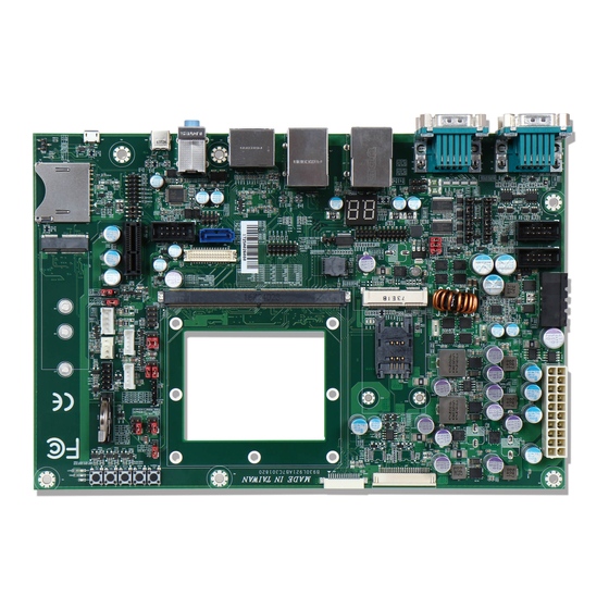
PSMC-C301 User’s Guide (Official R2.0) 2 Product Overview The primary purpose of this section is to present a general overview of MITWELL’s SMARC 2.0 compliant carrier board - PSMC-C301. By providing detail schematic and functional design information in this manual, the PSMC-C301 carrier board provides manufactures and developers with a platform to jump-start the development of systems and applications based on SMARC specification. - Page 8 MITWELL PSMC-C301 User’s Guide (Official R2.0) Connector: J12 : SATA Connector J16 : Wafer 4Px1 P=2.5mm 4-Wall (SATA Power) JP20 : BH5Px1 (Back Light0 -- LVDS) JP23 : BH5Px1 (Back Light1 -- eDP) J55 : 3.5mm Triple HD Audio Jack Light Blue/Green/Pink (Audio) J58 : Box Header 5Px2 P=2.54mm (COM2)
- Page 9 MITWELL PSMC-C301 User’s Guide (Official R2.0) JP24 : PH3Px2 (LVDS1 Backlight Select) JP36 : PH3Px1 (RTC Select) JP38 : HEADER3P/2mm (I2S_Audio Line_IN & Line_OUT & MIC_JD) JP39 : HEADER3P/2mm (M.2 & Micro USB Select) JP53 : PH3Px2 (Boot Select) Copyright © MITWELL 2017...
-
Page 10: Specifications
250 mm x 170 mm 3.2 Power Supply The PSMC-C301 carrier board supports standard 20-pin ATX power supply (J54) and 9V – 36V DC variable power supply via pheonix connector (J71). JP54: Standard 20-pin ATX Connector (20P) The PSMC-C301 used with standard ATX (Connector X20) power supplies. The -5V and -12V power outputs of the ATX power supply are not used. -
Page 11: Atx / At Power Supply Mode
Auto Power Button Enable *2-3 Auto Power Button Disable (Default) 3.2.2 Power Status LEDs – D30, D31, D32 LEDs D30-D32 indicates the status of different power voltage input on PSMC-C301. D32 – PS_ON D31 – VCC3_IN D39 – VCC5_ON Copyright © MITWELL 2017... -
Page 12: Connector Subsystem
MITWELL PSMC-C301 User’s Guide (Official R2.0) 4 Connector Subsystem 4.1 SMARC Edge Finger Pinout Circuit Copyright © MITWELL 2017 PSMC-C301 User's Guide... - Page 13 MITWELL PSMC-C301 User’s Guide (Official R2.0) Copyright © MITWELL 2017 PSMC-C301 User's Guide...
-
Page 14: Communication Buses
PSMC-C301 User’s Guide (Official R2.0) 4.2 Communication Buses 4.2.1 CAN BUS PSMC-C301 features two CAN BUS over DB9 connector type for product with CAN BUS features. (CAN BUS is Not Supported by PSMC-M1011) J56A : D-SUB 9Px2 (CAN0) Signal Description Figure PIN No. -
Page 15: Serial Ports
MITWELL PSMC-C301 User’s Guide (Official R2.0) 4.2.2 Serial Ports The PSMC-C301 supports up to four serial ports: COM1 on D-SUB Connector (9Px2) at J57A COM2 on Box Header (5Px2, P=2.54mm) at COM3 on D-SUB Connector (9Px2) at J57B ... - Page 16 MITWELL PSMC-C301 User’s Guide (Official R2.0) J58 : Box Header 5Px2 P=2.54mm (COM2) Signal Description Figure PIN No. COM_RX#2 COM_TX#2 J57B : D-SUB 9Px2 (COM3) Signal Description Figure PIN No. 485D/422T-1 RS232RX/DT+1 RS232TX/422R+1 422R-1 RS232RTS1 RS232CTS1 Power(V_RI1) JP17: PH11Px2 (COM3 Function...
-
Page 17: Gigabit Ethernet (Gbe) And Usb
PIN No. COM_RX#21 COM_TX#21 4.2.3 Gigabit Ethernet (GbE) and USB PSMC-C301 provides two Gigabit Ethernet over RJ45 connectors with transformer and LEDs built in. (GBE0 at J82, GBE1 at J79). Two USB2.0 type A connectors are under GBE0 and two USB3.0 type A connectors are under GBE1 which supports USB2.0 as well. - Page 18 MITWELL PSMC-C301 User’s Guide (Official R2.0) J82 : RJ45+USBx2 Signal Description Figure PIN No. Power(VBUS_5) USB5-_P USB5+_P Power(VBUS_1) USB1-_P USB1+_P Power(GBE0_CTREF) GBE0_MDI0+ GBE0_MDI0- GBE0_MDI1+ GBE0_MDI1- GBE0_MDI2+ GBE0_MDI2- GBE0_MDI3+ GBE0_MDI3- LAN_C11 LAN_C12 LAN_C10 LAN_C9 Copyright © MITWELL 2017 PSMC-C301 User's Guide...
- Page 19 MITWELL PSMC-C301 User’s Guide (Official R2.0) J79 : RJ45+USB3.0x2 Signal Description Figure PIN No. Power(VBUS_2) USB2-_P USB2+_P USB2_SSRX-_P USB2_SSRX+_P USB2_SSTX-_P USB2_SSTX+_P Power (VBUS_3) USB3-_P USB3+_P USB3_SSRX-_P USB3_SSRX+_P USB3_SSTX-_P USB3_SSTX+_P TX1+ TX1- TX2+ TX2- TX3+ TX3- TX4+ TX4- LAN1_C11 LAN1_C12 LAN1_C10 LAN1_C9 Copyright ©...
-
Page 20: Display Interfaces
Signal Description Figure PIN No. Micro USB *2-3 M.2 (Default) 4.2.4 Display Interfaces PSMC-C301 provides the following display interfaces : DisplayPort(DP) on J62 (upper port) HDMI on J62 (lower port) eDP/LVDS/DSI on J64 Copyright © MITWELL 2017... - Page 21 MITWELL PSMC-C301 User’s Guide (Official R2.0) J62 : Display port + HDMI 90D (DP+HDMI) Signal Description PIN No. Signal Description Figure PIN No. HDMI_D2+_C DP0_LANE1-_C DP0_LANE2+_C HDMI_D2-_C HDMI_D1+_C DP0_LANE2-_C DP0_LANE3+_C HDMI_D1-_C HDMI_D0+_C DP0_LANE3-_C DP0_AUX_SEL_C HDMI_D0-_C HDMI_CK+_C DP0_AUX+_C HDMI_CK-_C DP0_AUX-_C DP0_HPD_C...
- Page 22 MITWELL PSMC-C301 User’s Guide (Official R2.0) LVDS0_0- / eDP0_TX0- / DSI0_D0-_C LVDS0_1+ / eDP0_TX1+ / DSI0_D1+_C LVDS0_1- / eDP0_TX1- / DSI0_D1-_C LVDS0_2+ / eDP0_TX2+ / DSI0_D2+_C LVDS0_2- / eDP0_TX2- / DSI0_D2-_C LVDS0_3+ / eDP0_TX3+ / DSI0_D3+_C LVDS0_3- / eDP0_TX3- / DSI0_D3-_C...
- Page 23 MITWELL PSMC-C301 User’s Guide (Official R2.0) JP19: PH3Px2 (LVDS0 Power Select) Signal Description Figure Function Power(VCC3) Power(VCC12) Power(VCC5) JP22: PH3Px2 (LVDS1 Power Select) Signal Description Figure Function Power(VCC3) Power(VCC12) Power(VCC5) JP21: PH3Px2 (LVDS0 Backlight Select) Jumper Setting Table Figure Input select...
-
Page 24: Sata
MITWELL PSMC-C301 User’s Guide (Official R2.0) 4.2.5 SATA PSMC-C301 supports one standard SATA connector at J12. The SATA LED (D22) lights up when an activity occurs on SATA interface J12 : SATA Connector Signal Description Figure PIN No. SATA_TXP SATA_TXN... -
Page 25: Pcie
MITWELL PSMC-C301 User’s Guide (Official R2.0) 4.2.6 PCIe PSMC-C301 provides four PCIe interfaces : PCIe x1 slot (PCIe LANE A) at mini-PCIe slot (PCIe LANE B) at M.2 slot (PCIe LANE C + LANE D)at J78 : PCIe x1_36Pin... - Page 26 MITWELL PSMC-C301 User’s Guide (Official R2.0) PCIE_B_TX- Test Point SMB_DAT Power(+1.5V_PCIE) PCIE_B_TX+ CLKREQ# Power(USIM_PWR) DF_USB_4N_C USIM_DATA PCIE_B_REFCK- DF_USB_4P_C USIM_CLK Power(+3V_4G) PCIE_B_REFCK+ USIM_RST Power(+3V_4G) LED_WWAN# USIM_VPP Test Point LED_WLAN# Test Point Test Point LED_WPAN# Test Point Power(+1.5V_PCIE) PCIE_B_RST# Test Point PCIE_B_RX-...
- Page 27 MITWELL PSMC-C301 User’s Guide (Official R2.0) CLK_PCIE1- PCIE_C_RST# Test Point PCIE_WAKE# Test Point SMB_DAT PCIE_D_TX+ SMB_CLK PCIE_D_TX- PCIE_D_RX+ PCIE_D_RX- Power(+3V_M2SSD) Power(+3V_M2SSD) PCIE_C_TX+ PCIE_C_TX- Copyright © MITWELL 2017 PSMC-C301 User's Guide...
-
Page 28: Sd Card
DAT2 WP#_COM CD#_COM 4.2.8 Audio Interfaces PSMC-C301 features one audio codes via HDA interface (REALTAK_ALC886-GR) and keeps with another I2S interface for ARM based product test purpose. J55 : 3.5mm Triple HD Audio Jack Light Blue/Green/Pink (Audio) Signal Description Figure PIN No. -
Page 29: Mipi-Csi
Figure PIN No. LINE_IN2_JD_P LINE_OUT2_JD_P MIC2_JD_P 4.2.9 MIPI-CSI PSMC-C301 features with two MIPI-CSI flat foil connectors: CSI0 supports up to two differential data lanes CSI1 supports up to four differential data lanes at Copyright © MITWELL 2017 PSMC-C301 User's Guide... - Page 30 MITWELL PSMC-C301 User’s Guide (Official R2.0) J92 : FPC 24P P=0.5mm Downside 90D (CSI0) Signal Description Signal Description Figure PIN No. PIN No. CSI0_TX+ / I2C_CAM_DAT_L CSI0_D0- Power(3.3V or 1.8V) CSI0_D0+ CSI0_D1- CSI0_D1+ CSI0_CK- Power(5V) CSI0_CK+ CSI_GPIO1(3.3V) CSI_GPIO2(3.3V) CSI0_RST#_L GPIO0 / CAM0_PWR#_L(3.3V)
-
Page 31: Other Connectors
MITWELL PSMC-C301 User’s Guide (Official R2.0) CSI1_D2+ Power(CSI1_3 or CSI1_1V8) CSI1_D3- CSI1_D3+ 4.2.10 Other Connectors J60 : FAN 4PIN Signal Description Figure PIN No. Power(VCC12) FAN_TACHIN(VCC5) FAN_OUT(VCC5) J61 : Box Header 5Px2 P=2.54mm (GPIO) Signal Description Figure PIN No. GPIO7... - Page 32 MITWELL PSMC-C301 User’s Guide (Official R2.0) J73 : Pin Header 7Px2 P=2.0mm 180D (ESPI) Signal Description Figure PIN No. ESPI_CS0# ESPI_ALERT0# ESPI_CS1# ESPI_ALERT1# ESPI_CK ESPI_RESET# ESPI_IO_0 Power(VCC1P8) ESPI_IO_1 Power(VCC3) ESPI_IO_2 ESPI_IO_3 U56 : SPI Flash Socket ※ Jumper shall be shorted at...
-
Page 33: Jumper Settings
MITWELL PSMC-C301 User’s Guide (Official R2.0) 5 Jumper Settings JP36: PH3Px1 (RTC Select) Signal Description Figure PIN No. *1-2 Power(RTC) (Default) RTC Reset JP39 : HEADER3P/2mm (M.2 & Micro USB Select) Signal Description Figure PIN No. Micro USB *2-3 M.2 (Default) J74 : PH4Px2 (Lid &... - Page 34 MITWELL PSMC-C301 User’s Guide (Official R2.0) JP53 : PH3Px2 (Boot Select) Signal Description Figure PIN No. 1-2, 3-4, Carrier SATA 3-4, 5-6 Carrier SD Card 1-2, 5-6 Carrier eSPI Carrier SPI 1-2, 3-4 Module device(NAND, NOR) Remote boot(GbE, serial) Module eMMC Flash...
- Page 35 MITWELL PSMC-C301 User’s Guide (Official R2.0) J88 : HEADER 5PX2/2mm(TPM) Signal Description Figure PIN No. SPI0_CK_R RESET_OUT#_R SPI0_CS1#_R GPIO8_R SPI0_DIN_R Power(1.8VDUAL) SPI0_DO_R Power(3VDUAL) GPIO9_R Copyright © MITWELL 2017 PSMC-C301 User's Guide...
-
Page 36: Additional Features
MITWELL PSMC-C301 User’s Guide (Official R2.0) 6 Additional Features 6.1 Power Button The SMARC module performs a power up sequence when you press this button. The power button is connected to the SMARC module’s POWER_BTN# signal. 6.2 Reset Button When you press this button, the SMARC module and all components connected on the SMARC will perform a hard reset.
Need help?
Do you have a question about the PSMC-C301 and is the answer not in the manual?
Questions and answers