Table of Contents
Advertisement
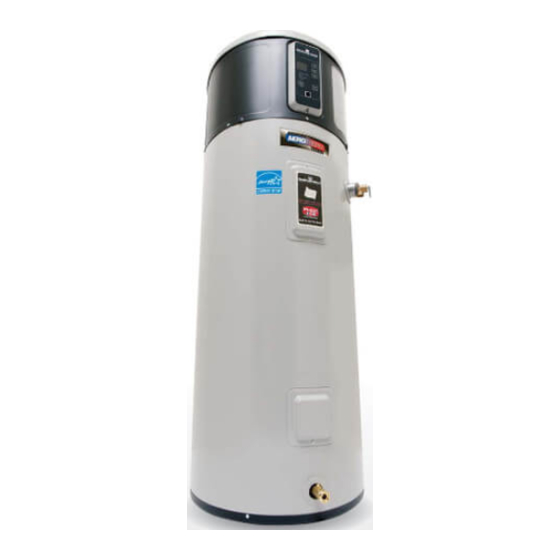
Heat Pump Water Heater
Important Safety Information ...2-4
Control Panel .......................................... 5
Powering Unit ......................................... 6
Temperature Setting ............................7
Operational Modes ...............................8
Care and Cleaning ........................... 10
Installation Instructions ................ 13
Troubleshooting Tips ...................... 19
Northern Climate Tier 3 Capable
Write the model and serial
numbers here:
Model # ________________
Serial # _________________
You can find them on the rating label
on the front side of your water heater.
Owner's Manual &
Installation Instructions
RE2H50R10B-1NCWT
RE2H80R10B-1NCWT
Chauffe-eau
résidentiel hybride électrique
Manuel d'utilisation
et d'installation
La section française commence à la page 24
Calentadores
de agua
residenciales eléctricos híbridos
Manual del propietario
e instalación
La sección en español empieza en la página 46
49-50301 08-14
Printed in USA
Advertisement
Table of Contents

Subscribe to Our Youtube Channel
Related Manuals for Bradford White RE2H50R10B-1NCWT


Summary of Contents for Bradford White RE2H50R10B-1NCWT
-
Page 1: Table Of Contents
Heat Pump Water Heater Important Safety Information ...2-4 Owner’s Manual & Installation Instructions Operating Instructions Control Panel .......... 5 RE2H50R10B-1NCWT Powering Unit ......... 6 RE2H80R10B-1NCWT Temperature Setting ......7 Operational Modes .......8 Frequently Asked Questions (FAQ) ..9 Chauffe-eau Care and Cleaning ......10 résidentiel hybride électrique... -
Page 2: Important Safety Information
IMPORTANT SAFETY INFORMATION. READ ALL INSTRUCTIONS BEFORE USING. WARNING! For your safety, the information in this manual must be followed to minimize the risk of fire or explosion, electric shock, or to prevent property damage, personal injury, or loss of life. Be sure to read and understand the entire Owner’... - Page 3 IMPORTANT SAFETY INFORMATION. READ ALL INSTRUCTIONS BEFORE USING. CAUTION! Risk of Fire - Hydrogen gas can be produced in a hot water system served by this water heater that has not been used for a long period of time (generally two weeks or more). HYDROGEN GAS IS EXTREMELY FLAMMABLE!! To dissipate such gas and to reduce risk of injury, it is recommended that the hot water faucet be opened for several minutes at the kitchen sink before using any electrical appliance connected to the hot water system.
-
Page 4: Operating Instructions
IMPORTANT SAFETY INFORMATION. READ ALL INSTRUCTIONS BEFORE USING. Safety Precautions WARNING: A. Do turn off power to water heater if If the water heater has been subjected to flood, fire, or physical it has been subjected to overheating, fire, flood or physical damage, turn off power and water to the water heater. -
Page 5: Control Panel
About the control panel. Control Features Display Filter Reset The filter is dirty and requires cleaning when the Red light is illuminated. Filter is located on top of the water heater. Operating Modes Press button and hold for 5 seconds to reset filter alarm. (See page 8 for description) Vacation (See page 8 for description) -
Page 6: Powering Unit
Turning on the water heater. There is no power button for this unit. Once the water heater is wired and power is supplied, it will be on. The display will show the current water temperature setting. Current operating mode for the water heater is illuminated. To comply with safety regulations, the controls are factory preset to 120°F (49°C) and Hybrid Mode. -
Page 7: Temperature Setting
About the water temperature setting. Temperature setpoint: To Adjust the Temperature Safety, energy conservation and hot water capacity are factors Follow these steps: to be considered when selecting the water temperature setting 1. Press the UP or DOWN arrow on the control panel key pad of the water heater. -
Page 8: Operational Modes
Operational Modes. Vacation This water heater defaults to the Hybrid operating mode. Available modes are listed below and can be selected using This feature is used when you will be away from the home for the MODE button. an extended period of time and hot water is not needed. In this mode, the unit will drop the water temperature down to 50ºF Heat Pump (only) Mode —RECOMMENDED FOR MAXIMUM... -
Page 9: Frequently Asked Questions (Faq)
Frequently Asked Questions. Filter: Q: Why is there a filter? A: In Hybrid and Heat Pump (only) the unit moves air through the system. The filter protects the unit from dirt. A clean air filter improves efficiency. Q: How to clean the filter? A: Leave power on and remove filter from top of unit. -
Page 10: Care And Cleaning
Care and cleaning. Routine Preventive Maintenance DANGER: Periodic Inspection (once a year): Risk of Scald - Before manually operating the relief valve, make certain no one will be It is further recommended that a periodic inspection of the exposed to the danger of coming in contact with the hot operating controls, heating elements and wiring should be made water released by the valve. -
Page 11: Cleaning The Filter
Care and cleaning of the water heater. Cleaning the Filter In the Hybrid, Heat Pump (only) and High Demand/Boost modes, After the clean filter has been reinstalled, press and hold the the heater moves air through the system and out the back of the FILTER button. - Page 12 Anode Rod Maintenance and Service. CAUTION - IMPORTANT SAFETY NOTICE Trim Ring This information is intended to use by individuals possessing Tape Process adequate background of electrical, electronic and mechanical Tube Pinch Off experience. Any attempt to repair a major appliance may result in personal injury and property damage.
-
Page 13: Installation Instructions
Installation Instructions LOCATION (CONT.) The location chosen for the water heater must take into consideration the following: WATeR HeATeR SIzINg INfORmATION - ReAd BefORe INSTALLINg: LOCAL INSTALLATION RegULATIONS Water Heater Temperature Setpoint: This water heater must be installed in accordance with these instructions, local codes, utility codes, The water heater temperature setting strongly impacts the amount of usable hot water available for showers and baths. -
Page 14: Thermal Expansion
Installation Instructions Catch Pan Installation (If required) LOCATION (CONT). Required clearances: Relief Valve Drain There must be a 7” (17.5 cm) clearance between any object and the rear and sides of the water heater in the event service is needed. A minimum 8“ (20.3cm) clearance above the Condensate Drain water heater to remove the filter for cleaning and for service access, and clear access to the front of the water heater, is... -
Page 15: Water Supply Connections
Installation Instructions WATeR SUPPLy CONNeCTIONS CONdeNSATION dRAIN CONNeCTION This unit has a condensate drain; therefore a floor or other Refer to the illustration below for suggested typical installation. The HOT and COLD water connections are clearly marked drain no higher than 36” (91.4cm) above the floor must be and are ¾”... -
Page 16: Relief Valve
Installation Instructions ReLIef VALVe TO fILL THe WATeR HeATeR WARNINg: WARNINg: Risk of Unit Damage - Risk of Unit Damage - pressure rating of the relief valve must not exceed 150 tank must be full of water before heater is turned on. The PSI (1.03 kPa), the maximum working pressure of the water heater warranty does not cover damage or failure water heater as marked on the rating plate. -
Page 17: Electrical Connections
Installation Instructions eLeCTRICAL CONNeCTIONS The manufacturer’s warranty does not cover any damage or defect caused by installation, attachment or use of any type of A separate branch circuit with copper conductors, overcurrent energy-saving or other unapproved devices (other than those protective device and suitable disconnecting means must be authorized by the manufacturer) into, onto or in conjunction provided by a qualified electrician. -
Page 18: Installation Checklist
Installation Instructions INSTALLATION CHeCkLIST 1. Tank location: – Does room size require louvered door or similar ventilation? 10’ x 10’ x 7’ (700 cu. ft.) or 240 square inches (0.15 m open air-flow area needed. – Back of unit away from wall by 7 inches (17.5 cm), and sides have at least 7 inches (17.5 cm) clearance. (6 inches (15.2 cm) clearance for earthquake strap installations, with additioanl clearance on the opposite side of the unit.) –... -
Page 19: Troubleshooting Tips
Troubleshooting… Before you call for service..Save time and money! Review the chart below first and you may not need to call for service. Problem Possible Causes What To do • Water heater makes A fan is used to move air Some amount of fan sound is normal. - Page 20 Troubleshooting… Problem Possible Causes What To do • Water is too hot Water temperature is set See About the Water Temperature Setting section. too high. CAUTION: For your safety, DO NOT attempt repair of electrical wiring, controls, heating elements or other safety devices. Refer repairs to qualified service personnel. •...
-
Page 21: Fault Codes
Fault codes. fault fault Condition Check Code Counts dis- Before played Code dis- played Control checks to ensure evaporator is free of frost. Check T3a sensor mounting, wiring and resistance. Continuously verifies that T3a sensor (evaporator inlet tem- Check Electronic Expansion Valve (EEV) operation. perature) is greater than 20F after 30 minutes of run time. - Page 22 Fault codes. fault fault Condition Check Code Counts dis- Before played Code dis- played T5 sensor (ambient temperature) failure. The control detects Check T5 sensor mounting, wiring and resistance. the thermistor output is at or nearly shorted or open circuit. Use service mode to monitor T5 sensor temperature.
- Page 23 Notes.
Need help?
Do you have a question about the RE2H50R10B-1NCWT and is the answer not in the manual?
Questions and answers
2 min of hot water then just cold.i reset the tank and it's been circulating but the **** has not kicked in. It's been almost 3 weeks of no hot tub water, and it is cold here in Maine this time of year
The Bradford White RE2H50R10B-1NCWT water heater could provide only 2 minutes of hot water before switching to cold due to several possible causes:
1. Heat Pump Operating Range: If the ambient temperature is outside the heat pump's operating range (35°F to 120°F or 2°C to 49°C), the heat pump will turn off, and the unit will rely on electric elements. If the elements are not functioning properly, hot water may run out quickly.
2. Hybrid Mode Operation: In Hybrid mode, heating elements quickly provide an initial amount of hot water before switching to the heat pump. If the heat pump is not running efficiently or is not heating water fast enough, hot water may be depleted quickly.
3. Electrical Issues: If the water heater is miswired and not receiving the correct voltage (240V AC or 208V AC), it may not heat water properly, leading to short hot water availability.
4. Fan or Compressor Issues: If the fan or compressor is not working correctly, the heat pump may not heat water efficiently, causing hot water to run out quickly.
Checking these factors can help diagnose and resolve the issue.
This answer is automatically generated